Inside the Gerdes Brake Master Cylinders

Source: 2015 Beartracks, Jared Yates
15q2zdThe brakes on some planes are almost optional, and some of the old-style planes like Bob’s Pietenpol didn’t have any brakes at all. This isn’t so with the Bearhawk– the brakes are a critical directional control and they are worthy of careful attention. Several of us are flying with the Gerdes long shaft (A-110-10) or short shaft (A-110-4) brake master cylinders. I have two of each. The long shaft cylinders have become scarce, but the short-shaft cylinders work just fine with the longer machined clevis. These are the cylinders that are available from Mark Goldberg at Bearhawk Aircraft, or from B&B Aircraft Supplies. The advantage of purchasing them from Mark is that he can provide the machined long clevis that makes the short shaft cylinders as long as the old long shaft variety, and that he provides the cylinders with a fresh set of O-rings and a corrosion inspection. At $140 per pair, they are still a good bargain. Compare to the Grove 670, which is a modern replacement with a machined outer body for $420 per pair.15q2zh Cleveland acquired Gerdes long before I was born and renamed the A-110-10 the 10-54, which is available for $679 per pair! After doing some unrelated work on the brakes, I found that when I pressed the left-left pedal, the brake would apply normally, but the pedal would not return to the usual position. The problem with this condition was that if I pressed the pedal again, there was no braking action. Fortunately I found this problem during bleeding and not during a ground loop to the right. Being that these cylinders had not had any maintenance in at least 8 years, I thought it was a good time to take them apart and replace the O-rings. Mark said it’s not uncommon for bad O-rings to cause this condition, and that it can also be caused by internal corrosion. It would probably be wise for builders to inspect these cylinders and replace the O-rings before the initial installation if they have been sitting for several years. In the initial construction stage, they are easier to get to and builders won’t have to drain the hydraulic fluid.
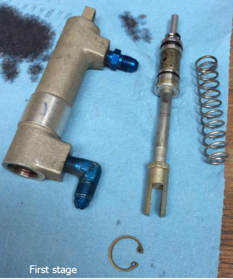
15q2zeAfter removing the cylinders from the airplane, I pointed the lower outlet over a waste oil bowl and worked the shaft a few times to drain the old fluid out. Interestingly, when I drained the fluid from the airplane, it was still bright red. The fluid that came out during this hand-operated step was dark purple, probably from worn aluminum particles. Next, I removed the top snap ring. The result is in the top photo, captioned “First Stage.” That giant spring is what should be returning the pedal back to the ready position, but in my case there was a lot of sliding resistance between the shaft and the “end gland” (the top, round aluminum donut that is held in place by the large, top snap ring). This explained the symptom, but not the problem. I can see how corrosion on the center shaft would have been a good culprit, but mine was corrosion-free. The cause was a bent shaft, as you can see in the picture. I’m not sure when or how this happened, but there it was.
15q2zfI was able to use a vice and some careful padding to straighten the shaft well enough to reduce the sliding friction. The shaft is very soft and easy to bend, and to straighten. Even though my problem was related to the bent shaft, I was still glad to be able to refresh the O-rings. As you can see in the photo below, the O-rings showed some wear and were looking square. Mark sells O-ring sets, but if you need to look for them locally, here’s what you’ll need to know. All dimensions are in inches, and you’ll need one of each per cylinder. I’d order extra –011s, because they are easy to damage when reassembling the cylinders. These O-rings are made from 70 Durometer Nitrile and are available from most of the usual aircraft suppliers, and may be available from some local industrial stores like Grainger and Fastenal.
15q2zg

Location MS Number AN Number Width ID OD
At Piston on Shaft MS28775-008 AN6227B-3 1/16 3/16 5/16
Top Gland Inner MS28775-011 AN6227B-6 1/16 5/16 7/16
Top Gland Outer MS28775-014 N/A 1/16 1/2 5/8
Piston Outer MS28775-111 AN6227B-9 3/32 7/16 5/8

The assembly process was very straightforward, with two minor notes. First, the piston has a chamfer on the center hole on one side only. That chamfer goes up against the –008 O-ring that sits on the shaft, so pointed towards the top. In other words, the top of the piston is shown in the “piston close up” photo. The other potential pitfall comes when installing the top gland back onto the shaft. Since the inner –011 O-ring has to pass over the threads on the top of the shaft, it is easy to damage them. I found the best technique was to lube the shaft (I used Boelube, but 5606 would probably be fine too) and use a rotating motion to thread the o-ring on, as opposed to pushing across the threads. The latter technique led to little bits of rubber being stuck in the threads. When seating the top gland and snap ring, I used a deep-wall 1/2” socket to press evenly on the gland. This seated it deep enough to fit the snap ring inside the cylinder housing, then a second press of the socket on top of the snap ring popped it right into place. The cylinders now all operate smoothly, and hopefully leak-free for the next few years.

Leave a Reply

Leave a Reply