Making Fiberglass Wingtips with a Male Mold

Source: 2016 Q1 Beartracks, Mike Swain
020I want to offer this disclaimer, prior to this excursion into wingtip making my composite experience was limited to patching a few screw holes in boats over the years. My objective is not to save money or time by building my own wingtips; I want to learn and hopefully end up with something unique. I wanted Hoerner style wingtips, primarily because I like the way they look, but there are some purported performance advantages over rounded. The Hoerner shape also lends itself to housing the Bob Archer style VOR antennas I made.
021
Stuff You’ll Need:

  • MDF to make 2 full size airfoil forms
  • Enough foam to make 2 wingtips the thickness you require
  • Fiberglass Cloth & Resin (Epoxy or Vinylester)
  • QuickFair or filler of your making
  • Lightweight spackle or Polyurethane+Microballoons
  • Sandpaper – I suggest 80 – 120 – 220
  • Nichrome wire – 22 gauge
  • Foil Tape, min 1.5 inch wide
  • Power source for hotwire – Battery Charger, etc.
  • High Build Primer

To start, I rough cut a piece of MDF and set it up against the outboard edge of my wing and traced the airfoil with a sharpie. I cut to the line using a band saw and jig saw. I then used a random orbital sander to finish until the line was just gone.
My plan was to mount the tips flush, not overlap, so I reduced the form by another .0625″ to allow for the fiberglass layup thickness. I drew a line .0625 in from the edge by using a scrap piece of aluminum the correct thickness and dragging it around the form with a sharpie. I then sanded the form down to the new line. Because I need two identical forms to hotwire the foam, I traced the completed form onto another piece of MDF and rough cut. Using a few screws, I screwed the two pieces of MDF together and used a flush cut router bit to make an exact copy of the first form.022
023The two forms will sandwich the foam and the hotwire will glide along the forms resulting in a airfoil shaped block of foam. The two forms need to be exactly in line with each other during this process. I am sure there are many ways to ensure the forms are inline, but I simply match drilled the forms with a couple of 3/8 guide holes while the forms were screwed together which threaded rod will go through lat-er in the process.
I made my wingtips 10″ wide, primarily because a single 4’x8′ sheet of 2″ foam supplied enough material. But you can make them any width you want, just glue together enough foam.
024
025
Using a framing square, I laid out lines on my workbench to match the distance between the 3/8 guide holes in the forms. The width of my wingtips are 10″, so the layout is 10″ + 1.5″ to account for the 2 MDF forms. I then made 4 supports from some scrap 1×2, 2 for the front and 2 for the rear. The pairs were match drilled and long enough to suspend the forms and foam in the air over my bench. I drilled the 4 sup-ports with a Kreg jig I use for wood joinery, but it’s perfect for attaching wood at right angles. You’ll also want to ensure the ends mounting down to your work surface are square, I cut mine using a chop saw.
I used one of the airfoil forms to trace the airfoil 5 times on my 4’x8′ sheet of 2″ thick polystyrene foam I picked up at Home Depot. I also drilled the foam through the 3/8 guide holes while I was tracing the airfoil. I rough cut the sheet into 5 pieces using the tracings in the previous step. I used an old hand saw I had laying around.
The foam I purchased had foil on 1 side and plastic on the other. I peeled this off so I could glue the 2″ pieces together to get 10″ total. I used 3M 78, which is a foam-safe spray adhesive. If you use a different glue, test it on some scrap foam, because many of the solvents in glue will eat polystyrene, especially the spray adhesives.
To glue everything together, I ran 2 threaded rods up through the guide holes on one of the forms so the rods were sticking up in the air. I slipped the first piece of foam down over the rods then sprayed the inside end with adhesive along with the subsequent joining end of the next piece. Rinse and repeat until you get to the last piece. You don’t want adhesive on the outside ends be-tween the forms and foam, we just want to glue the pieces of foam together to get our desired thickness. I slipped the second form onto the rods and snugged the whole assembly together while the adhesive dried. I went for tight but I didn’t want to crush the foam.
Once the adhesive is set, you are ready to hotwire. I set up the assembly using the 4 supports screwed down to my workbench, so the forms and foam are suspended over my bench.
I made a hotwire tool with a scrap piece of 1×2 and some scrap fuel strap (.025 4130 bent at 90 degrees) It needs to be wide enough for the width of wingtip you are building. You want the wire to glide along the two MDF forms. I purchased the Nichrome wire from Amazon. The wire needs to be as tight as possible. For a power source I used a car charger. It seems the newer digital chargers are smarter than the old dumb transformer types, so I used an old 12V UPS battery to trick my charger into putting out the juice.
Once you have your hotwire tool ready, it’s time to cut some foam. The idea is to have the wire glide along the top of your forms at a nice slow steady pace. Not too fast to drag the wire, but not too slow where you burn excessive foam. You can fix most imperfections when you fill the foam, but try to get a clean cut. Do one side, then flip the whole assembly in your supports and do the other side. Take it out of the fixture and you now have an airfoil shaped chunk of foam the thickness of your planned wingtip.
Now we will create the Hoerner shape. To do this, we will apply foil tape along the edge of the foam for the hotwire to ride on. On the lower inboard side of the wingtip, I made a line 1 inch from the edge. I carried this to about the center of the front of the air-foil. Now on the TOP of the OUTBOARD edge of the airfoil, I came down about .25″ inch from the edge. There is nothing hard and fast about .25. but this will determine the thickness of the outboard edge of the wingtip. If you want thicker, make the dimension bigger.(right)
To hotwire this, I plunged the hotwire into the foam until just making contact with the foil tape, then gently drug the wire trying my best to keep the wire square for a nice even pull. The video shows this in more detail.
Now you’ve got a funny looking airfoil-hoerner sculpture (above). The next step is to put the front radius on. From this point on it’s more up to you and how you want the final shape to be. I followed the convention outlined in the video (https://youtu.be/RoOh-fgI8oU) which is to use the width of the wingtip as the radius of the front curve, 10″ in my case. I am happy with the look and the way it came out. I used a piece of safety wire around a sharpie to draw the 10″ radius from the front inboard edge of the airfoil to outside edge. I then used my hotwire tool held vertical to the foam and rough cut the radius.
You will end up with a blunt edge on the front of the airfoil where you cut the radius. Use a rough file or rasp to blend this blunt edge into the existing airfoil. I went ahead and ever so slightly radiused the outboard edge of the wingtip to the point where the airfoil is the thickest. Seems to be about 1/3 of the way back from the front. This was done by eyeball until I got a pleasing shape.
I then used some 80 grit sandpaper to rough sand any ripples from hotwire and generally level the foam. I used some 120 to put a nice radius on the outboard edge of the wingtip. You don’t want any sharp edges since wet fiberglass will pull away if you try to layup over a sharper corner.
I then used some lightweight spackle to go over the form. Then a process of sand, fill, sand, and fill. You want a nice smooth surface under the layup. Any imperfection will transfer into the fiberglass. I read in the Bingelis book that Polyurethane mixed with Microballoons makes a good mix to cover foam forms. I had already used spackle before I found that tidbit, but you might want to explore that method. You’ll want to make sure the entire form is covered, because paint and certain resins will eat foam.
026
After getting things as smooth as possible, I put a couple of coats of rattle can spray paint. I used orange because I wanted to be able to see the form as I was laying up, to make sure there were no air bubbles.
To prep for layup, I waxed the painted form with 4 coats of good carnuba car wax I had in the garage. I then sprayed 3 coats of PVA mold release.
My layup schedule was 4 layers of 8.8 oz Bi-directional cloth from Aircraft Spruce (PN 01-00642). There was no science in that choice, just a guess. They seem to be pretty sturdy and came out around 7 lbs. each.
I used System 3 Silver Tip Epoxy as my laminating resin. It is a popular choice among home boat-builders. No amine blush and simple 2:1 mix ratio. It can also be post-cured at higher temps to improve the structural properties, which is a bonus for room-temp cured epoxies. Make sure your foam is 100% protected if you use Polyester or some other non-foam safe resin…..or all that hard work will melt away.
027
I will not go into detail on attachment, but I ended up using piano hinges. I didn’t want to have to undo a bunch of screws every year at annual. I followed the steps the RV guys have outlined. The only exception is I built an access panel on the top of the wingtip to access the hinge pins, since the Bearhawk’s tip rib extends all the way back, unlike the RV method of securing the hinge pins.
I followed this method: http://goo.gl/lRg0i2. I used .040 strip of 2024 as my spacer, since there is no cutting of these wingtips. Also, since there is no gelcoat on my homebuilt wingtips, they were translucent enough for me to mark the hinge and drill based on marking on the hinge.
Once I had the wingtip mounted, I used Quick Fair (a commercial fairing compound) to level and get a nice surface on the wingtips. This requires several thin coats and lots of sanding. I use a 3M semiflexible longboard. 80 grit for rough, then 120, then 220. Depending on the quality of finish you want will determine how much time is spent here.028
I applied high build epoxy primer next, sanding between coats, until i got a perfect surface. Once you are happy, they are ready to be painted or further modified for lights, etc.
I will be making cutouts and fabricating lenses next. My landing, strobe and position lights will be housed in each wingtip. I hope to write up those steps in a future article.
029

Engraved Panel Art

Source: 2015 Q4 Beartracks
Builders Eric and Brent of Charlotte NC send this photo of an engraved plate they made to decorate their Bearhawk project. Most of their initial fabrication work is complete, and now they’ll disassemble the airframe and prepare for covering, paint, and final assembly. Readers may recall the article about their all-metal Bearhawk from earlier this year.
15q4zh

4-Place Forward Elevator Bellcrank Angle

15q4zgNotice that the positioning of the elevator bellcrank is not arbitrary. The photo to the right shows an excerpt of the plans page 26. This depiction shows where the bellcrank should be in the neutral elevator position. When making elevator cables, be sure to establish this alignment. Incorrect alignment will cause higher cable tensions at deflected elevator positions. Also, Bob recommends using galvanized control cable for most Bearhawks, and not stainless cable. The stainless cable is still safe, but it has a less favorable fatigue resistance, and will likely wear out faster. An early hardware list specified stainless cable instead of galvanized, but that was not the best choice for planes that will not see service on floats in salt water.

Drill a Drain in Your Airbox!

Source: 2015 Q4 Beartracks, Russ Erb
Recently I had a very odd transitory problem with Three Sigma. I flew it on a Monday and put it away. I came back to do something on Tuesday and it was fine. Then on Wednesday I went to the hangar and there was a large blue dye spot in the oil drip pan under the engine. It had suddenly developed a large fuel leak. While trying to find the source of the leak, a “large” amount of fuel came pouring out of the cowling (probably just a few ounces, but disturbing nonetheless). It stopped before I could figure out where it was coming from. I checked the fuel inlet fitting (which had sprung a leak before) and it was dry. Everything else on the outside of the carburetor was dry.
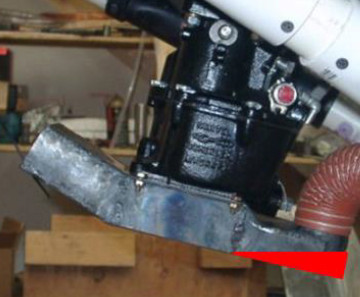
For some reason, I thought to check the carb air box through the carb heat exit hole. I was greatly surprised to find the rear half of the carb air box full of fuel. The fuel I found is represented by the red triangle on this picture of my carb air box. As best I can tell, the fuel leak may have been a problem with the float shutoff valve releasing fuel into the carburetor barrel which ran down and some of it collected in the air box.15q4zf
Apparently the problem magically fixed itself (always weird) because there has not been a single drop of fuel leaked in four days since the initial problem, even with the Mixture Full Rich and the auxiliary fuel pump on.
However, this experience highlighted a much bigger potential problem. It is possible through a failure in the carburetor, or even just over-priming or otherwise flooding the engine, for fuel to collect in the rear part of the carb air box. At best, when I test carb heat that fuel will get pulled into the engine and flood it. At worse, the heated air (for carb heat) flowing over the fuel would blow it around the cowling and eventually the fuel would catch fire.
The solution was very simple-the carb air box needed a drain hole, so that fuel would not have a chance to accumulate in a large quantity. I drilled a #40 hole at the back of the air box. Yes, there will be a little bit of air leakage through the drain hole, but comparing a #40 hole of cold air to a 2 inch SCAT of heated air, I figured the difference would be imperceptible. Problem presumed solved. Continue reading

The Bearhawk Patrol Takes a Trip to the WAD

(Wentworth Aerodrome, New Hampshire)
Source: 2015 Beartracks, Lauren West
15q4zaThe Bearhawk Patrol in all of its glory was ready to go. I was as ready as I could be. I had been in the air a dozen times but this was my first week long trip. I have known Bob Barrows for most of my life. I started making fiberglass parts for the Bearhawks about 5 years ago. After working on other R&B Aircraft projects and learning more about the Bearhawks, I decided I wanted to fly them. First thing first, I will need a license and knowledge of flying. I can’t think of a better way to get things started than an adventure in a Bearhawk Patrol with Bob.
I planned to leave on Tuesday morning, October 6, 2015 in the Bearhawk Patrol with Bob. Earlier plans to leave had been cancelled due to flooding. Therefore we were ready to go at the first chance we had. We were loaded up and ready to jump into the Patrol and go at 9am, but it was very foggy still. We stood on the runway waiting for the clouds to move out of our way and the fog to lift over the mountains. At 10am we could see the mountain tops and had clear skies to the northwest and thick clouds to the southwest. So we jumped at the chance to go. With thick clouds out one window and beautiful mountains out the other we headed north on our adventure.15q4z
Not knowing what to expect in the week ahead, I hoped to learn as much as possible and have fun. That is exactly what I did. With the help of wonderful hosts, Rick Papp’s, Mike Mitchell, and John Meade, my trip was awesome. I met an exciting group of people and everyone was willing to help teach me and answer any question I had.
When we met up with the Ohio Bush pilots near Warren Ohio on the way to Papp’s Airfield, the group consisted of pilots Rick Papp, John Graham, Don Emslie, T.C. Williams, Jim Kusan, Terry Dow, Lou Furlong, Bobby Cox, and of course Bob Barrows. Papp’s place is new and still under construction, but looks great. 9 planes landed there on the new dirt strip with no problem. Road traffic stopped and pictures were taken during the excitement of the Cubs and Bearhawk arrival. The Papps family took all of us in, filling their home and shop with pilots and gear.15q4zc
The next morning, being a group of bush pilots, we all took off between the clouds. Having a beautiful flight with an ocean of clouds below us and above us, I found the hand held radio under my seat in the Bearhawk Patrol and started to listen in on the chatter. I overheard several of the pilots say that our destination coordinates had been changed. I then heard them mention that “Bob can sniff out an airport.” Good thing because I had just learned how to turn the GPS on! I got plenty of practice though, because of our sightseeing throughout the day, which included the Curtiss Museum. Bob and I greatly enjoyed the museum exhibits of Glenn H. Curtiss’ inventions and the local history.15q4zb
Wednesday afternoon we landed on Mike Mitchell’s beautifully manicured grass airstrip at Old Forge, New York, in the Adirondacks. Here I was able to take some time to look at the other planes in our group, Super Cubs, Carbon Cubs, and Scouts, which were all excellent. Mike provided wonderful hospitality in his beautiful home which had room for us all.
The next morning we had an enjoyable flight to Island Bob’s for his lunch fly-in. There we met up with some more Bearhawks that were on their way to the WAD fly-in as we were. Island Bob’s airstrip was on a river island near Albany, New York.
At about 3pm our group of 9 joined about 20 more planes at the WAD (Wentworth Aerodrome) in New Hampshire. It was the biggest turn out ever according to the Meades, owner and hosts. Friday night we had a buffet with Alaskan Crab legs and Salmon flown in fresh from Alaska. Then we discussed the Saturday Fly-out route. There were many different ways this massive group of pilots prepped for the next day’s flight with the detailed flight plan info handout. GPS, aviation maps, and smart phone aps were all used, so I was able to learn many navigational methods.15q4zd
Saturday morning we had a hearty breakfast at the Meade’s before our 9am departure with about 30 planes. With 8 airstrips to explore I was excited to go. All the stops were unique; some were corn fields, some were on the beach. The coast line of New Hampshire and Maine was gorgeous and my favorite. But Bob and I really enjoyed the opportunity to look at the airplane workshop at Cooper Farm, New Hampshire, it was a highlight attraction. We met everyone for lobster rolls at Bailey’s airstrip in Maine, where I met a few more Bearhawks. One family mentioned that they have the 4-place Bearhawk for the extra kid space that they were definitely using. After a very successful Fly-out we stayed at the WAD one more night before heading home. Naturally, we spent the evening beside of the campfire telling stories of flight adventures and misadventures. Hilarious tales of travel all over the world- hunting, fishing, skiing, and of course the fly-ins. Listening to the stories secured my desire to take the opportunities I have to do what it takes to get my pilot license. I truly had a lot of fun on this adventure. I learned a bit about navigation and a variety of airports, but most of all the people I met along the way encouraged me and pointed out infinite amounts of ways that flying a plane will be greatly beneficial for my family and career.15q4ze
As we flew home I couldn’t help but notice how much my perspective changed, I loved flying. This is definitely something I would like to do again.

Building a Patrol Fuselage Using a Tubing Kit from Bearhawk Aircraft

Source: 2015 Q4 Beartracks, David Edgemon
15q4qDuring Oshkosh this year I was wandering through the Bearhawk booth when Mark Goldberg suggested that he had “just what you need.” I’m mostly scratch building a Patrol but have purchased a few parts from Mark. When he told me that he had a Patrol pre-fit tubing kit that was available, it took all of 10 seconds to accept. I’m sure glad I did.
The tubing kit is a collection of about 150 tubes that have been precut, bent, fish-mouthed, and fitted into Mark’s steel fuselage jig. That’s about 300 fish-mouthed joints that are already complete! It’s a huge time saver. All of the tubes are labeled with numbers and either “left”, “right”, or “center” tags. These are referenced to a pair of drawings of the fuselage frame. These two drawings along with Bob’s plans provide all of the detail that’s really needed for assembly.15q4r
The factory guys paint all of their tubing with some cheap paint in order to color code the wall thickness. This helps prevent errors with picking the wrong size tube. You can see in the photos that I have removed the paint and scale from the joint areas prior to tacking the tubes. This allows a nice clean metal joint to weld.
When scratch building the fuselage conventionally, we build a jig and fit each tube to the jig. Well, with the tubing kit it is essentially reversed. The tubes have already been in the jig, so the challenge is to put them back together square and plumb.
I started by laying out the ceiling frame on a flat table. This piece is almost completely flat with just a little joggle in the forward area. The longerons are pre-bent to shape and by fitting the pieces together from back to front, we easily are able to assemble the ceiling frame. I used layout lines on the table for reference and to keep things square, but the tubes pretty much dictate the placement.15q4s
The lower fuse frame is a bit more complicated since we have a 2 substantial bends in the longerons. The lower longerons are pre-bent and the scarf joints are made for the tubing size changes.
At this point I started building supports to hold the lower frame at the correct angles and positions. You can probably see plumb bobs in the various pictures. These were principally used to keep the bottom and top frames aligned to the long center line on the table. Once the basic placement was established I let the upright and diagonal tubes dictate the final assembly of the structure.15q4t
A simple set of wooden uprights were screwed to the table in order to position the top of the fuselage over the bottom assembly. The cross braces were set to heights roughly measured from the plans, but during assembly some adjustment was made to allow the uprights to fit correctly. Remember we’re fitting the jig to the tubing not the other way around.
During all of this process the fit of the tubing was excellent. I was worried that as I worked my way forward towards the more complex portions of the fuselage that I might start suffering from tolerance buildup. Fortunately this was minimal. I had very few tubes that needed a small touch up. That was probably due to fitting the aft sections more tightly than needed.
15q4uOne thing that became apparent during the assembly is the HUGE number of clamps that were necessary to hold things in position before tacking. Some of the most useful clamps were these “EAA” welding clamps. They are cheap to make and very versatile for holding multiple tubes while getting ready to tack. I used 4 of them plus a lot of the common spring clamps.
The forward fuselage and firewall area is definitely the most challenging, with more complex clusters. The 5 firewall tubes were numbered but were not found on the plan sheets. A little study and it became obvious which tubes were which. This is the only error or omission that I found in the drawings.
All in all I was very pleased. The fuse took about 4-5 weeks of very part time work (mostly weekends) to lay out and tack. This is much faster than I would have achieved from plans only. The only thing left is to weld in the engine mount support tubes and I’ll be ready to mount the fuse to a rotisserie and start final welding
15q4v
15q4w
15q4x
15q4y

New Stainless Exhaust Supplier

Source: 2015 Q4 Beartracks, Bob Barrows
These photos are of a stainless steel exhaust system copied after my de-sign, which I have been using with very good success on all of my proto-type Bearhawks. This set shown was built by Andre at Plane Xhaust in Fort Lauderdale, FL 866-312-4122 (they also have a website), for the Patrol built by Eric Newton, that I sold to Andy Corsetti in FL. The price is very good at $800.00/set. Thank you Andy for getting this done.15q4p

Ventral Fin for Floats

Source: 2015 Q4 Beartracks, Paul Minelga
15q4jFirst of all, a disclaimer about this article…I AM NOT AN EXPERT!!! I’m just a homebuilder like everyone else, muddling my way through a really big project. One of my criteria for a homebuilt is to put it on floats. That’s the genesis of all this research on the subject and the search for the answer to the somewhat elusive formula: To fin, or not to fin?
What is the definition of a ventral fin as it relates to aircraft? One writes: “A fixed vertical surface on an airplane that extends below the aft end of the fuselage. Ventral fins are used to increase the directional stability of an airplane.” And now the why: “Sometimes they are added after flight testing shows that the original design was inadequate, or after mods that may affect the lateral stability of the airplane (check out the Beech 1900D). 15q4kAlso, if a landplane is converted to a float plane, the additional forward vertical surface area of the floats requires a balancing vertical surface area aft, either in the form of a ventral fin or vertical stabilizer fins on the horizontal stabilizer.” So now that we know that ventral fins are used on a variety of aircraft, not just float planes. So how does that apply specifically to an airplane on floats?
The size of the fin is really dictated by the frontal area of the floats, control in flight, tail and fuselage surface area, engine size, prop size, etc, etc. According to Al Robinson, his Lycoming O-360 powered Bearhawk on Clamar floats didn’t seem to need a fin. 15q4lOn the other hand Mike Carriere with the yellow Bearhawk with the monster IO-550 and large floats can barely put enough additional vertical area on the tail on to make it controllable. Mark Scott is an aeronautical engineer by profession and built a beautiful Bearhawk. Here’s what he has to say from some previous emails that I had saved: “As an aerodynamicist I have done some aircraft stability work. The need for additional area on an airplane is a function of prop size and float size. The fact than an O-360 Bearhawk with regular floats needs less ventral fin than an IO-550 on large floats makes sense. By looking at the Bearhawk I’m pretty sure it would benefit from some additional area. The FAA directional stability certification requirement is that an oscillatory decay from a rudder doublet pulse damp down to 1/10th amplitude in seven or less cycles. One could make a survey of float equipped aircraft out there and the size of their ventral fins. A plot could be made to figure out how much ventral fin area would probably work well on the Bearhawk. I think in the end pay an extra pound or two and make a good sized fin that looks right. That is what I am going to do when I put my plane on floats. I recommend making the largest reasonable-looking sized ventral fin. They are not difficult to make. If the directional stability feels really solid you could make another smaller one. Another trick is to install much stiffer rudder return springs. I think there is an STC for Pipers and some Cessnas for this modification.”– Mark Scott15q4m I have been looking at the float installation on the Bearhawk quite a bit and ventral fin attach points were on the list of things to do. The Bearhawk that has flown on Clamar floats apparently has done well. For his installation, it looks like a ventral fin is unnecessary. But, if you choose to go with a different float, a fin may be necessary to compensate for the float size. I plan on EDO 2870s.15q4o
I started by looking at similar aircraft: the Aviat Husky and a Maule on floats. Both aircraft had a similar configuration and both had ventral fins. (See pictures) I measured everything, took detailed pictures of EVERYTHING and made a pattern of the fin that was on the Maule. After I got all the data back and did some measurements, I discovered that Bob Barrows had located the front ventral fin attach point at Station G/K, which is over two feet further forward than either of the other production aircraft (January 1999 issue of Beartracks). The ventral fin in the picture is almost five feet in length, tip to tail. If it was built to fit all the way to Station G/K, it would be just over seven feet long! (See the picture to the right for a size comparison)
15q4n
I called Bob and asked him about that fitting at Station G/K and why that location. He thought the fin could be longer and not as wide, but other than that, no other reason. After explaining what I had for measurements with the Husky and Maule, he agreed that the attach point would be better at Station H. There are two diagonal tubes that meet in the center of Station G where the fin attach point is. I asked him if there would be a need for a similar configuration at Station H/J and he said no. The cross tube was sufficient for any side loads, but if the fin got bumped from underneath, it would be a good idea to put a 3/8ths by .035 tube from the center of the fitting up to the apex of Station H/J to take any vertical load. (See picture) He said you could make the tube go straight into one of the diagonals, or at a bit of an angle where the two meet at the top. This is where the vertical stabilizer attach point is offset by 3/4ths of an inch. Either way would be ok.
I was ready to make the ventral fin when I came across a fin from a 1978 Maule M-5 on Craigslist. I jumped at the chance to have an actual production fin to look at as opposed to just making an semi-educated guess as to its construction. I was surprised after I stripped off the fabric to see how much structure there was to the fin. Originally I thought it was just a couple of tubes with some brackets at the top, but it was quite a bit more involved with four different sizes of tubing. Most of the photos of the fin and my construction is found on my kitlog web site (www.mykitlog.com/yeeeha), so I won’t repeat it here. But for a few details that aren’t apparent, I did a few changes from the Maule design. On the front mount I made it like the Husky, utilizing two AN-4 bolts instead of four. I used .062 for making the front and rear fittings on the fin. On the fuselage end of things I did things a bit different than what was in the January 1999 issue of Beartracks. I made my mount at Station J out of .071 (what I had) and made it to mirror the size of the mount pad on the fin, which is quite a bit more substantial than Bob’s original idea. I do plan on adding the 3/8ths .035 tube, but I have to buy some first…I ran out!
To summarize: For my build, two-blade Hartzell prop in front of an IO-540 C4B5 and using EDO 2870 floats, I decided that a ventral fin will be necessary and I now have one that will certainly do the job. Hope this all makes some sense and good luck on your builds!

At Home in the Bearhawk

Source: 2015 Q4 Beartracks, Jonathan Battson
Southern Alps of New Zealand, seen flying south in the whereabouts of Arthur’s PassPerhaps the thing I like the most about aircraft is the ability to leave the city and arrive in the depths of the backcountry in next to no time. It creates the flexibility to plan trips in a way which would otherwise be impossible. In our case, we usually fly home. On this particular occasion, we had a week at our disposal and plans to hunt chamois and go trout fishing.
For us, home means 3 hours and over 700km south, crossing the open ocean and non-stop overhead the Southern Alps. This is landscape of extreme, unforgiving terrain and home to rapidly changing weather; a place to be enjoyed with one eye on the sky at all times. My good buddy Nicholas joins me.
Based from our home town of Wanaka, there are places to do all three activities within less than 30 minutes flight time. But there is a complete lack of paved or even improved surfaces to land on. The Bearhawk is right at home here, taking us straight from the fuel pump to the fish pool in less time than your average TV show.
First up is trout fishing. With overcast conditions, we set out looking for clear flowing water and sighted fishing for rainbow trout. The first river we check is cloudy with silt flowing due to rain in the top of the large watershed. Not deterred, we travel on. Skipping over into the next valley though a mountain pass, we tuck in between rain clouds and pass through the falling virga. Here we find what we want, crystal blue water and flat places to land. We fly low up the valley, examining both the pools and the available landing places.
We select a spot and make our first pass, to spot driftwood and any large rocks. On this occasion the spot is tight, so I elect to make a second lower pass at a known airspeed. This gives me confidence about the length of the spot and another chance to see anything which might cause damage during the rollout.The Bearhawk parked and waiting patiently, notice the small grade of stones on the landing site.
Circling around and pulling full flaps, we approach at 40 knots indicated with a high nose attitude. In order to keep the tailwheel off the rough surface, and to minimise damage to the stabilisers, I pitch the nose forward just as the wheels come within a foot of touching the ground; making a wheeler landing. The landing is a nonevent.
Within an hour of two, my buddy and I have managed to land a nice fish each, on the fly. His a jack weighing in at 7 ¼ pounds, which was the first one to land. It was holding up deep in a pool and took a lot of convincing to accept our various offerings. Mine was a larger hen closer to 8 ½ pounds, which followed in quick succession at the tail of the pool. This fish was a fighter and took some landing, including a couple of jumps which put the tackle to the test. Both are released immediately after the fly is removed.
The author plays a Rainbow on a 5lb tippet.
Thoroughly satisfied and tired of swatting sandflies, we retire to the aircraft. After collapsing the rods and stowing them in the baggage tube, we climb in and start to warm up the engine which is stone cold by this time. As we finally depart the rain starts falling, so we get to lose a little paint from the leading edges on the way home.
A unique experience, flying and fly fishing!

The following day, after the worst of the weather had cleared; we collected a different set of equipment and made our way back to the airport. We made our way back into the Alps on a relatively short yet bumpy flight. The winds were still blowing strongly at right angles to the valley we needed to fly. We entered the valley at 2000ft well clear of terrain on a gradual climb. The airstrip is located at 2,600ft and we would be descending relative to terrain as we tracked up valley. The weather was changing rapidly and we soon struck rain.Final approach in less than ideal conditions- this is a tense time men-tally preparing for whatever happens next.
As we approached the airstrip I slowed to 65kts and selected 3 notches flap, easing the turbulent buffeting. The final approach takes us over a rocky creek and close to some beech trees, requiring a steeper descent and a late turn to line up with the airstrip. I apply full flap and slow to 50kts, taking account of the 10kt gusts. I think about the wet grassy surface as droplets of water track up the windshield, it will be slippery. The gusts worsen as we pass the trees, and the aircraft suddenly starts to fall sharply. I add power to catch it, creating unwanted speed as we accelerate toward the threshold. Closing the throttle completely we touch smoothly 40ft in. The strip is about 750ft long.
A shaft of light illuminates the valley floor, as the aircraft tugs on its anchor lines.As we start to slow with basically no braking action, we strike a powerful crosswind gust over our left wing. It’s the prevailing wind shooting out of the watershed which drains at right angles to the airstrip. I’m alarmed as the aircraft lifts some weight off the gear, slews right, and begins to depart the airstrip. Applying full left rudder and brake, but no power, we skid sideways, the nose is point at least 15 degrees left to our track. My hand is tense on the throttle, the “get me out of here” button with 260 horses in waiting. The situation improves as momentum catches up with us, the wind eases, and our direction of travel becomes the same as our heading again. I work the rudder stop to stop, and even out the brake pressure. We slide to a stop with both wheels locked.
This is an eventful landing.
I taxi us into the lee of an alluvial bank, spin tail into wind and shut down. Our first concern is getting doubled anchors into the ground and tie downs fitted, smartly followed by gust locks, watertight pitot cover, the cowl and intake plugs.
We start to relax and we don our wet weather hunting gear, but the weather seems to be softening. With packs on and rifles strapped over our shoulder, we stroll away from the aircraft. The fast moving clouds open and a shaft of light shines through.
A healthy population of Chamois, viewed through a 14x scope.After some hours using the binoculars, interspersed with climbing uphill, we sighted what we were after, a family group of twelve chamois with large Buck in attendance. The European Chamois arrived in New Zealand in 1907 as a gift from the Austrian Emperor, Franz Joseph. They are considered a threat to native plants and hunting is encouraged year-round. There are no laws governing flying and hunting on the same day, in contrast to some places.
We closed the gap on foot over the following two hours, until we ran out of cover and could close no further. By the time we’d reached this altitude, the wind was really howling; we were experiencing the full 28kts the flight computer had been registering on the way in that morning. It was now mid afternoon, and we were running out of time. At 250m we still had a long shot given the screaming wind blowing across our faces. Fortunately we are well versed in ballistics and well practiced at longer ranges.The old one-horned chamois Buck, a keen eye can spot the aircraft still right-side up in the distance.
As we readied ourselves for the coup de grâce, I noticed the Buck had only one horn! This is highly unusual. After some consideration, we decided he still looked healthy, and we were able to make a perfect shot. Holding a full “mildot” right of target to allow for the wind drift effect on the bullet.
We gathered the meat, trophy head, and the complete winter pelt from the chamois. Loaded with more than we could fit into our backpacks, we started the winding descent back to the valley floor. By the time we arrived back at the Bearhawk, we had limited daylight remaining. Tired, we heaved our spoils and equipment into the cargo area, removed wet clothes and boots, and then set about preparing the aircraft. The wings rocked vigorously with the wind as we hurried aboard. Warming the engine took time in the freezing conditions, but at last we were ready to roll.
Takeoff in the Bearhawk is always an occasion, but never very difficult, especially on straight grass surfaces where there’s little need for big control inputs. The winds hadn’t improved, but in our tired state neither of us was complaining on the ride home. We both appreciated the fact that the Bearhawk was saving us a two hard days walking plus a long drive.The trip back north for work is always accompanied by mixed feelings, but not always by such other-worldly panoramas.
The remainder of our week-long trip was spent in a similar fashion. With a modicum of bad weather, and one or two other “eventful” moments, and that will be a tale for another time. As we departed back towards New Zealand’s imaginatively named North Island on the dawn of a Sunday, we were greeted by an omen that another change in weather was brewing over the Tasman Sea. Gazing into the luminous red sky, we cruise climbed toward 12,000ft at almost 120kts ground speed. With just a handful of words, we agreed we had definitely made the right choice of backcountry aeroplane some two years earlier.