A Corvair Engine for the Bearhawk LSA

Source: 2024 Q1 Beartracks, David Swartzendruber
I am building a Bearhawk LSA and one of the engine options for the LSA is a Corvair auto engine conversion. This is what I have chosen for my LSA and I completed my engine build at the end of 2023 during a 3-day supervised build in William Wynne’s shop in Florida. Bob Barrows and William Wynne worked together to design a motor mount for the Corvair engine in the Bearhawk LSA and this mount is available from William. But I’ll back up and start at the beginning of my story.
Like many of you, I decided I wanted to build an airplane many years ago, about 33 years ago for me. However, along the way I lost that dream when it didn’t seem like time or money would allow that to happen. About five years ago, that dream was rekindled when I picked up an unfinished non-Bearhawk project for a very affordable price that was designed to use a VW engine conversion. As I thought about what to do for an engine, I came across the Corvair and William Wynne’s website, Flycorvair.net, and began to consider using a Corvair engine in that project. Through the information on Flycorvair.net, I also discovered the Bearhawk LSA was a good candidate for the Corvair engine and I became less enthusiastic about the project I had acquired. I eventually decided to order a Bearhawk LSA kit and sell the other project.
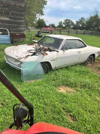
Having already started down the path of building a Corvair flight engine, I thought I would go ahead and complete that while I waited for my LSA kit to arrive. The first step is to get a conversion manual from William Wynne. This manual includes information about which core engines can be used to build a flight engine. I picked up a 1965 Corvair parts car for $250 and the engine from that car became my core. Corvair flight engines always start with a 1964-1969 engine because engines earlier than that had a smaller stroke, lower displacement and lower strength crank and rods. My core engine was locked up, but I was still able to disassemble it and discovered that the piston rings on one piston had rusted to the cylinder wall. To my surprise, I found that my 1965 engine had a crankshaft and rods from a 1963 or earlier engine. This ended up not making any difference because I decided to go all out and build the bored and stroked version that bumps the displacement up from 164ci to 200ci, also referred to as the 3.3L. The 3.3L engine requires a new billet crank, billet rods, forged pistons and special cylinders so my old crank and rods weren’t needed anyway.
I shipped my engine case and heads off to Sport Performance Aviation (SPA) in Florida for machine work on the case and heads and complete rebuild of the heads. Larger holes are bored into the case to accommodate larger cylinders and some clearance machining is done inside to allow the rods on the stroked crank to clear the case. SPA developed the 3.3L stroker parts, so I bought the new crank, rods, pistons, rings and cylinders from SPA. In addition, SPA has developed a 5th bearing system for the front of the crankshaft to react the propellor loads not normal to an automotive application. All the other standard conversion parts from William Wynne are also used in the 3.3L stroker, so I ordered those from William, including:
-Prop hub, safety shaft and hybrid mounting studs
-Ring gear, starter and aluminum top cover
-Billet aluminum oil pan with oil pickup tube and screen
-Oil filter housing, oil cooler adapter and AERO-Classics oil cooler
-Rebuilt oil case with high volume oil pump
-Rebuilt distributor with Willam’s dual ignition conversion
-Reground camshaft developed by Crane cams for William Wynne
-Alternator mounting bracket
-Modified valve covers to add oil fill tube and vent ports
-Billet aluminum pushrod tubes
-Rotec throttle body injector
-Stainless steel intake and exhaust manifolds
-Engine mount for Bearhawk LSA
-Fiberglass nose bowl
-Engine baffles are coming later but are also offered by William
Once I had all the parts, I began to assemble the engine. The case came back from SPA already closed with the crankshaft, camshaft and 5th bearing installed. This would normally be done at home on the lower displacement engines, but on the stroker motor SPA wants to make sure everything goes together with adequate clearance and rotates freely. I installed the hybrid studs, safety shaft, prop hub and ring gear on the front of the crankshaft and then added the oil case to the rear of the engine.
At this point, I masked things off and painted the engine case and rear oil case. I also cleaned up the new cylinders and painted them. More assembly would have followed from here, but I had decided to take advantage of the supervised engine build opportunity that William Wynne offers. I traveled to Florida with my partially assembled engine and all the other parts and over the course of three days, completed the engine build and test ran it on Williams test stand with a club prop. I liked the idea of spending 3 dedicated days and completing the engine and I also valued the opportunity to run the engine on the test stand and learn from William while I was there.
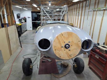
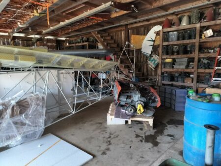
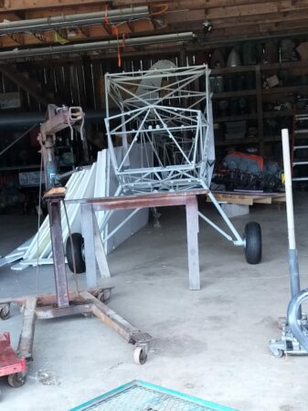
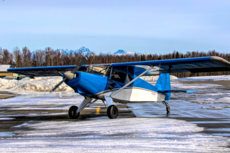
The amount of calendar time that passed during this whole process was greater than I originally thought it would be so I already had my LSA kit for 11 months by the time my engine ran. Of course this meant that when I returned home from Florida, I couldn’t resist installing the engine on the front of the airplane even though there is still a lot of other work to do on the fuselage. I got ahead of myself and installed the nose bowl to the prop flange, but now I need to go back and install the boot cowl before I can complete the cowling. The typical engine cowling used with the Corvair engine is very similar to the standard Bearhawk cowling. William Wynne sells a fiberglass nose bowl sized for the Corvair engine and then a sheet metal cowling is fabricated to go between the nose bowl and firewall with doors that open for easy pre-flight inspection.
Besides providing parts for converting Corvair engines, William Wynne provides education about the engine. Not just how to build the engine, but also how to own, operate and maintain the engine. I referred to a conversion manual that William sells, but there is also a Maintenance, Operations and Procedures manual that helps you through the flight test period and developing a POH for your aircraft. The support that William provides and the Corvair community that exists are a big part of why I decided to use a Corvair flight engine. I think there are some similarities between the Corvair community and the Bearhawk community in that I believe both draw more of the old school type homebuilders than you find in some of the other homebuilder circles.
For those of you who are interested in more details about the Corvair flight engine in general, I’ve listed some information below that largely comes from William Wynne’s website, Flycorvair.net.

More about the Corvair:
The Corvair is a General Motors designed engine, manufactured by Chevrolet. 1.8 million engines were built in the Tonawanda, NY engine plant between 1960 and 1969. The Corvair has been flying on experimental aircraft since 1960, and William Wynne has been working with them as flight engines since 1989.
Configuration: The engine is a horizontally opposed, air-cooled, six cylinder configuration. William only promotes its use as a simple, direct drive power plant. The engine configuration is very similar to Lycomings and Continentals.
Displacement: The engine is effective without a gearbox or belt drive because it has a comparatively large displacement. William supports versions that are 2700, 2850, 3000 and 3300cc. The smallest of these is twice as big as a Rotax 912. The 2850cc is very popular because it sits in a sweet spot for performance and value.
Power: The power ratings for these four displacements of Corvair flight engines are 100hp, 112hp, 116hp and 125+hp at 3000 rpm.
Weight: The 2700cc engine weighs 225 lbs ready to run.
This is effectively the same as a Continental O-200. It’s installed weight is 35 lbs more than a 912 Rotax, 25 lbs more than a Jabiru 3300 and 40 lbs lighter than a Lycoming O-235. 2850cc and larger Corvairs are slightly lighter than 225 lbs because the cylinders weigh about 5
lbs less. 3300cc Corvairs also use a billet crank which saves another 4 lbs. Aluminum pushrod tubes can be used on any of the engines to save another 1 lb.
Reliability: From the factory, the Corvair made up to 180 hp in the car and turned more than 5500 rpm. The flight engine is reliable and long-lasting because it is only operating at 55% to 70% of these levels. Conversion engines that run at the car’s red line rpm historically have short lives and cooling issues.
Cooling: The Corvair has a factory cylinder head temp limit of 575F. This is the highest limit on any mass-produced air-cooled engine ever built. The engine is also the first mass-produced turbocharged car. GM engineered the engine to have excellent heat tolerance and heat dissipation. In aircraft the engine typically runs at 325 to 350 CHT.
Parts availability: Every wearing part in the engine has continuously been in production for 5 decades. A high end Corvair conversion only has an original pair of cases, and oil housing and cylinder head castings. All other parts in the engine, including the crankshaft, are brand new. Many of the parts in the engine, like the lifters and valve train, are common to Chevy V-8s. There is no part availability issue.
Ignition: The fleet of flying Corvairs is about 500 aircraft. More than 90% of them have a dual ignition system built by William Wynne. His system uses two mostly redundant systems, one points based, the other a digital electronic system. The design has two of every part potentially subject to failure, but it utilizes one plug per cylinder. Six cylinder engines can fly on one cold cylinder, most four cylinder engines cannot. Plug fouling is unknown in Corvairs because the ignition system is 40,000 volts and uses a plug gap twice as wide as a magneto system.
Fuel: The Corvair can use either 100LL or automotive fuel. It is not bothered by ethanol in the fuel. When Corvairs were designed, car gas was a lot like 100LL; for the last 35 years every mile driven by Corvair cars was done on unleaded car gas. Many engines like 912s and modern car engines do not have exhaust valves that can withstand the corrosive nature of 100LL. William uses stainless and Inconel valves in Corvair flight engines.
Maintenance: The Corvair is low maintenance. The heads never need re-torquing. The valves have hydraulic lifters and never need to be reset or adjusted. William dislikes the term “maintenance free” because it implies a “no user serviceable parts inside” disposable appliance mentality. The Corvair is a solid, robust machine which holds its adjustments, but his program is aimed at teaching builders to be self-reliant owners.

My donor car:


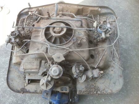
Engine removed from car


Engine after disassembly


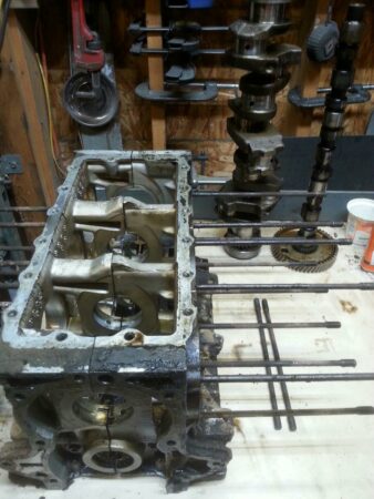
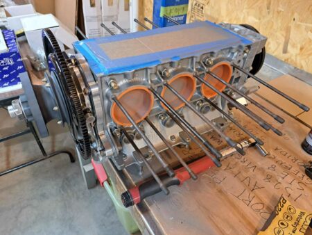
Bottom end as it returned from SPA


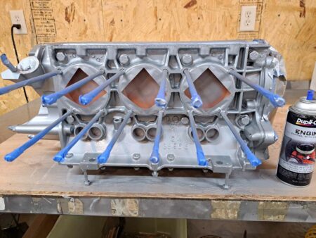
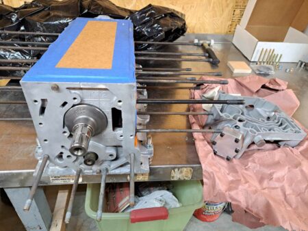
Bottom end after adding rear oil case, masking and painting


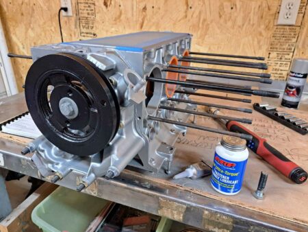
Masking removed and harmonic balancer added to rear of engine


Prop hub and ring gear added to the front of engine


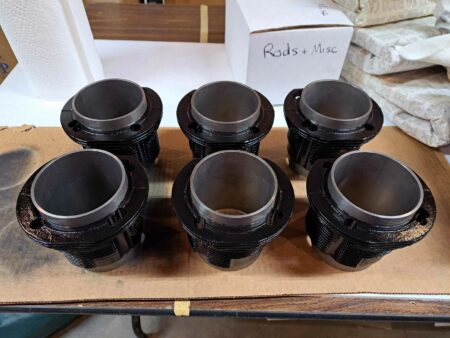
New cylinders painted


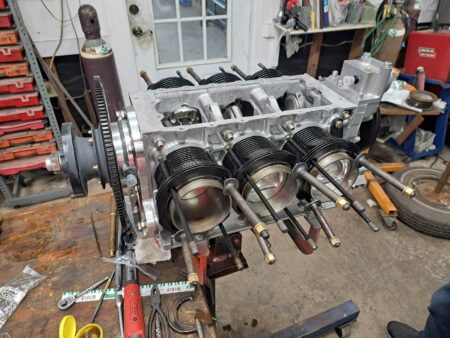
Now at William Wynne’s shop in FL. Rods, pistons and cylinders installed.


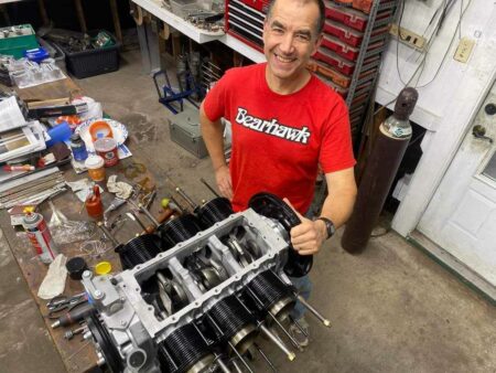
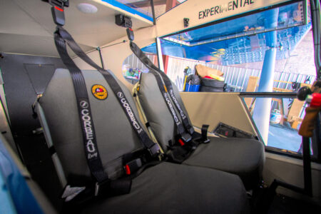
Showing off my Bearhawk gear


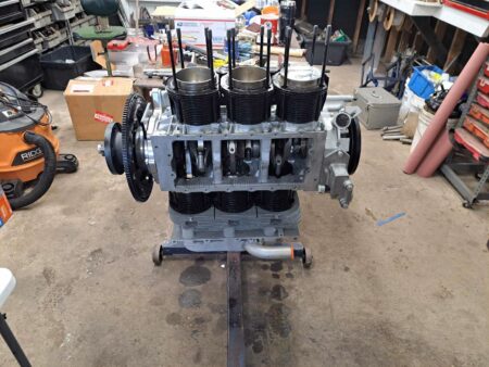
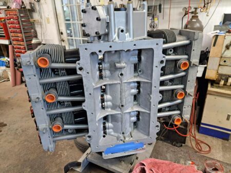
Engine is repositioned to install the head from the top and then rotated to install the second head from the top as well.


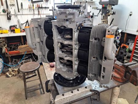
Second head now installed and engine moved to the vertical stand


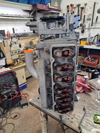
Valvetrain now installed


Ready to install oil pickup screen and oil pan


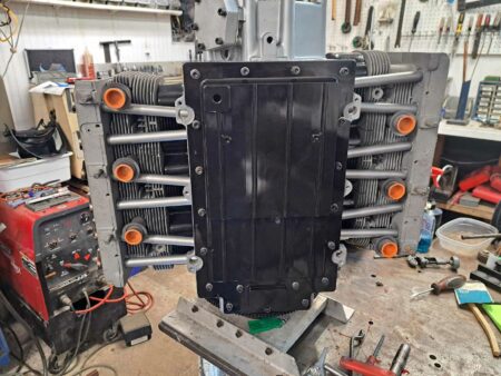
Oil pan now installed


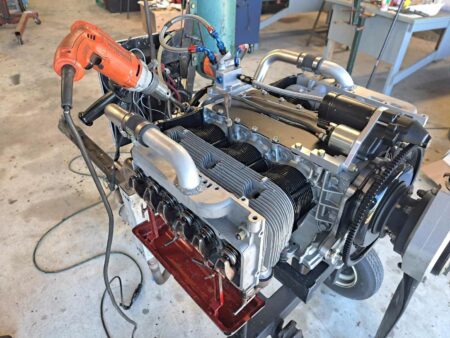
Engine has moved to the test stand. Top cover, starter and oil filter housing now installed. Drip trays mounted on heads to catch oil during pre-oiling process performed with drill motor spinning the oil pump.


Pre-oil is complete, valve covers installed, and cooling shroud added in preparation for test run.
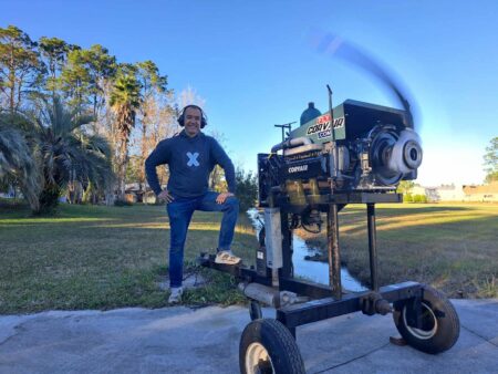
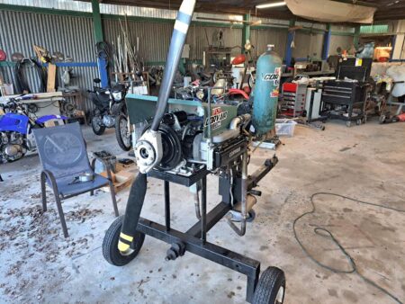

And it runs!


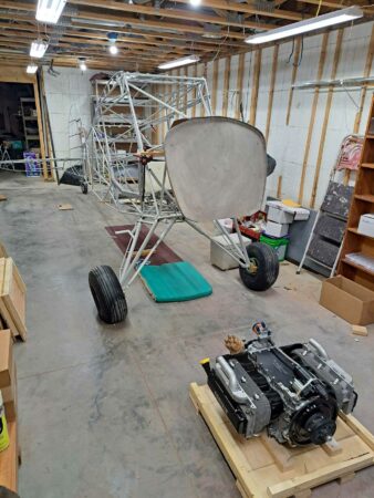
Back in Kansas, engine is waiting to be mounted on my LSA.


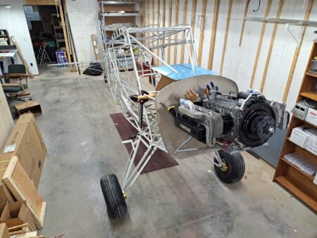
Engine mounted with William Wynne’s engine mount. The Corvair uses a bed mount.


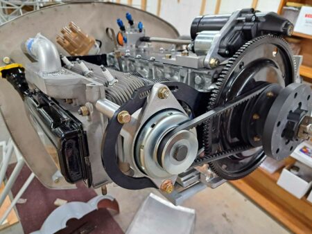
20A alternator now installed.


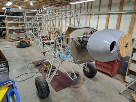
Nose bowl installed. This nose bowl is designed to use the 13″ spinner from Van’s Aircraft.

DIY Seat Upholstery

Source: 2024 Q1 Beartracks, Mark Richardson
Those of us who are building (or have built) an airplane know that there is a lot to learn over and above being a pilot. Leaving aside manual skills, we need to learn about the rules and regulations for building and licensing, avionics and electrical design, AC-43.13B contents and how to actually do … stuff … correctly, it’s the manual skills that are the bread and butter of aircraft building and the most fun.

With all models of the Bearhawk you need to learn how to rivet (both solid and pop), work metal (bending, forming, filing, etc), do fabric covering, run cables, install the engine, fit and prep fibreglass, cut, trim, and fit plexiglass, and a plethora of other detailed skills. If you are brave (stupid?) enough and decide to scratch build, you also need to learn to weld, operate metals shears and brakes, build and align jigs, and so on. There are lots and lots of jobs and skills you will learn by building an airplane.

A couple of the jobs that are often farmed out to the pros are aircraft painting and seat upholstery. I had already learned to paint an airplane when I built my RV-8 20 years ago (Google C-GURV) so although I am using a completely different paint process this time (Stewart vice Imron), it wasn’t totally new.

Which brings me to the purpose of this short article; how I upholstered my aircraft seats (your mileage may vary, batteries not included). I had considered (very seriously) just buying upholstered seats and carrying on. However, three things made me change my mind: 1) this would be a new skill that might be fun to learn, 2) I’m now retired so I have time, and 3) OMG it is expensive to have seats professionally done! I won’t lie, I found this the most challenging thing to learn yet. But it was actually fun and I am, well, not richer, but certainly not poorer by hundreds of dollars by doing it myself. I can’t give a step by step how-to with measurements and detailed instructions otherwise this article would be book length. However, I will show a bunch of pictures with descriptions of what is happening and notes on things to think about and avoid. Yes, even you can learn to do this.

The tools and materials:
We have a 60 year old Singer sewing machine that we bought fully restored a couple of years ago. No fancy computer features but it is indestructible and works great. You’ll need pinking shears for the fabric, regular scissors for the foam, sewing clips, rulers, marking pens, paper/cardboard for templates, tape, spray contact cement and a work surface. I used an electric carving knife to carve up the foam for the seat parts.
For the fabric I used RipStop because it is quite inexpensive, is super tough, it won’t give me third degree burns on a sunny day like leather, and actually looks really good. You’ll need some backing foam (1/2” or 1cm) that has a backing material on it, and foam for the seat bases and back. I got the Confor Foam seat bases from Aircraft Spruce for the front seat bases and used 2” firm upholstery foam for the rest.

The Method:
I made templates out of paper and cardboard for the various components of the seat cushions that were then used to cut out the fabric, backing foam, and to lay out the sewing lines. After a LOT of trial an error (mostly error), I added 3/4” on all sides to my fabric and backing foam patterns and just snipped off the excess at the end. Once the fabric pieces and backing foam were cut out, I used spray contact cement to apply the fabric to the foam (this is temporary to keep everything in place for initial sewing). I then used the paper template to mark on the back of the foam where I wanted to sew. Again, trial and error taught me to sew with the fabric side down as the feeder foot (or whatever it is called on the sewing machine) worked way better this way.

Once you get the various individual parts made you need to put them together. The trick is to overlay the existing sewn seams on the two sides such that when you sew the pieces together the seam disappears. Use LOTS of clamps. I put an extra 2” of material where the fabric would wrap around the back of the seat so there is material to pull on to tighten the fabric then staple. I used 1/4” birch ply with lightening holes as the backing material and stapled the fabric to the ply. The ply is quite light, and since the RipStop weighs almost nothing, the seats are not at all heavy. I will use Velcro to attach the seat components to the actual seat frames.

I realize this is hardly a “this is how to do it” article, but I hope it is an encouragement to try it yourself the next time you need seats for your airplane. The most expensive part of the whole thing were the Confor Foam seat bottoms ($200 CAN each!!). The rest was very inexpensive with the RipStop material < $5/running yard. Our own Michel Roy is the one who inspired me to do this with the seats he made for his Bearhawk using RipStop and between looking at his pictures and watching a BUNCH of YouTube videos, I was able to produce these:

Bearhawk Aircraft Update Spring 2024

Source: 2024 Q1 Beartracks, Virgil Irwin
For those of you who don’t know yet, my wife Mackenzie and I purchased Avipro, the kit production company behind the Bearhawk Quickbuild kits. Mark Goldberg offered the company to us last July at Oshkosh, and after six months of due diligence and number crunching, we decided it was something worth investing our future into. We have been very grateful for the support and encouragement from the community as we begin this new venture. I’m sure everyone has lots of questions and many have reached out already with their thoughts and concerns. We have a to-do list about a mile long, but we are doing our best to get everyone’s parts out the door and questions answered as we continue to work on our new advancements in the company.
First, the manufacturing will be staying in Mexico. The guys at the factory are exceptional craftsmen and I have always followed the motto of if it’s not broken, don’t fix it. There are still lots of parts manufactured here in the US, and as we move things forward our goal is to bring everything we can in house, this helps to keep costs down and ensure the highest quality product at the end of the day.
As we prioritize the tasks that need to be accomplished, the one task that sticks out the most is build manuals. Starting in April we will be constructing new build manuals that will be of a hybrid nature. There will be a written step by step manual with parts schematics, pictures and instructions. To go along with these written manuals there will be an overview video that goes with each section, giving visual guidance and tricks to accomplish each task. For years the task of building a Bearhawk has been very daunting simply from a project management point of view.
My goal with these manuals is to close the gap for the builder, increase completion rates, and decrease completion time. We have to start somewhere and currently there are the most people building the Five. After the manual is complete for the Five, we will start into the other models. The most likely order will be the Five, Patrol, Companion, Four, LSA.
The Web Store. What is it? What will be available? The store will be a complete one stop shop for you to get everything Bearhawk. Seatbelts, lights, avionics, tires, wheels, electrical, batteries, cables, fabric, paint, spare parts, merch, etc. For the scratch builders, there will be major assemblies available for purchase such as landing gear, shock struts, engine mounts, seats, etc. Wing kits and Fuselage kits are still available individually if desired. We recently got the warehouse moved and are working hard on new OEM
partnerships to provide the most complete product offering at the most affordable price. Recent new partnerships include Whelen, Desser, Garmin, E-mag and many more. We will begin adding products shortly and we are excited to offer this service to the community.
Thank you to everyone for continuing to support Bearhawk and the community that surrounds this company. Aviation truly brings some of the best people together and the Bearhawk community is by no doubt the best community to be involved with. Continue reading

Bob Barrows Begins a Bearhawk Companion Build Spring 2024

Source: 2024 Q1 Beartracks
So far only one example of the Bearhawk Companion is flying, though a few others are close! When it came to the Bearhawk 4-Place, Patrol, and LSA, Bob built the first prototypes and completed the flight testing and validation himself. The Bearhawk Companion worked out differently, and once Bob got to see and fly the first completed Companion, he knew he wanted to build one. Being that a Quick-build kit was available, it didn’t make sense to build the same way he made his prototypes. His kit arrived on January 26th, 2024, and he went right to work. As of press time he has the fuselage on the gear, the boot cowl and firewall installed, and the wings finished. He says, “Building an airplane is a lot easier when this much of it is already done!” Bob’s grandson Erin has also helped occasionally with the kit. Erin is half way through A&P school and is excited about airplanes.

Bearhawk 4-Place N316BH First Flight

Source: 2024 Q1 Beartracks, Scott Hoover in Alaska
N316BH, serial number 1266, is a plans build 4-place original model with some B model upgrades. I purchased the plans and many of the materials from a local man in Alaska who decided to go another direction with his build. It was built with a fair number of parts purchased from Bearhawk Aircraft and the VR3 Engineering tubing kit. N316BH has the original wings and tailspring but I upgraded the horizontal stabilizer, the door formers, and I re-enforced and strengthened the aerodynamic gear shock-struts with an internal round tubing. A skylight was added and lowered to match the wing across the top. I also reinforced the frame and welded a float kit along with ski cable attachment points.
The interior is simple and light with painted fabric. I kept my panel simple as well. I went with the MGL Xtreme EFIS and EMS along with a panel mounted iPad mini and two AHRS units that provide ADSB and air data to the iPad. All said and done I was pleased with my empty weight and CG. With the Bob Barrows O-540 and a metal two blade 84″ Hartzell propeller installed the empty weight came in at 1420 lbs. The CG is just aft of the forward limit with a pilot in the seat and empty fuel tanks. This leaves the entire CG envelope available for cargo, fuel and passengers. Impressive design for sure! My initial impression after just a few flights is WOW!!! What an incredible airplane! Very few things in life can beat that first flight! This was my first build and my first flight in a Bearhawk. After a couple of engine runs per the Lycoming instructions and a couple of taxi tests I was ready for the big event! After one more detailed inspection and one final run up I lined up on runway 20R at the Birchwood airport in Chugiak Alaska. It was a perfect day: 28 degrees, clear skies and little to no surface wind. The pressure altitude was well below sea level so I suspected great performance. Once on the runway I pushed the power up to 1200 RPM and let the plane slowly accelerate while taking one more concentrated look at the EMS, satisfied, I pushed the throttle on the untethered engine up to full power for the first time. She roared to life! I was thrown back in my seat with far more pressure than I have ever felt before in a single engine piston aircraft, it was at that moment that the smile came on my face and lasted for the next hour. The plane literally leapt off the runway before I even got the throttle to it’s stop. To my relief the airplane felt perfectly rigged and I rocketed to 3000′ at my planned 100mph climb speed. The first flight was all about engine break in and basic controllability checks. Fortunately, there are no issues other than some avionics problems that I’m still working through.
My overall impression of the Bearhawk is that it is perfectly designed for mechanically inclined individuals to build, even from scratch, with little experience in building aircraft. The great majority of the airplane is constructed using very basic metal working skills. The project took me nearly 7 years to “complete” as a hobby with many distractions along the way.
The plane feels light and even sporty in the air. It is wonderfully powered with an 0-540 and stable at high and low speeds yet still extremely responsive to flight control inputs. I look forward to exploring the entire flight envelope as I work through my flight test profile.

Original Scanned PDF Version of 2023 Beartracks Newsletters

You are not yet authorized to view this page. Learn more here.