Beartracks 2026 Issue 1 – Technical Q&A with Bob

Technical Q&A With Bob
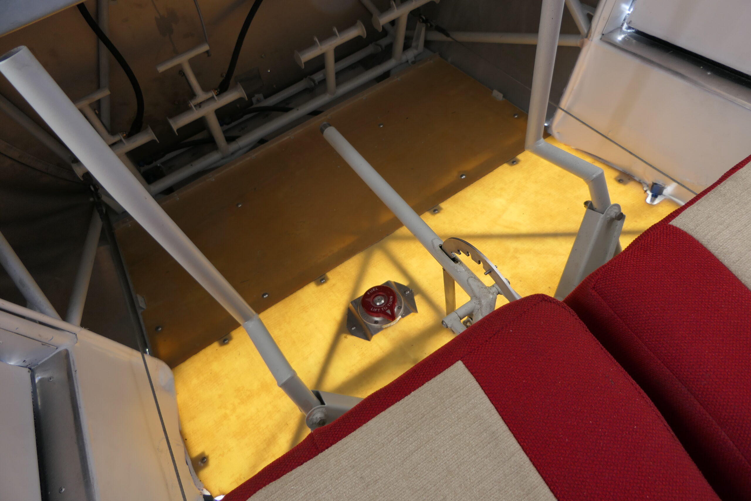
Builder Matthew Brennan asks about Bob’s use of aramid composite floorboards in his latest plane, instead of aluminum. Matthew says, “Curious if the Kevlar floorboards “sound” any different than aluminum when in flight.  Is “drumming” reduced?”
Bob says, “I wear ear plugs when I fly and it’s hard to tell for sure due to all of the rest of the noise, but the composite floorboards should help dampen some of the noise.”

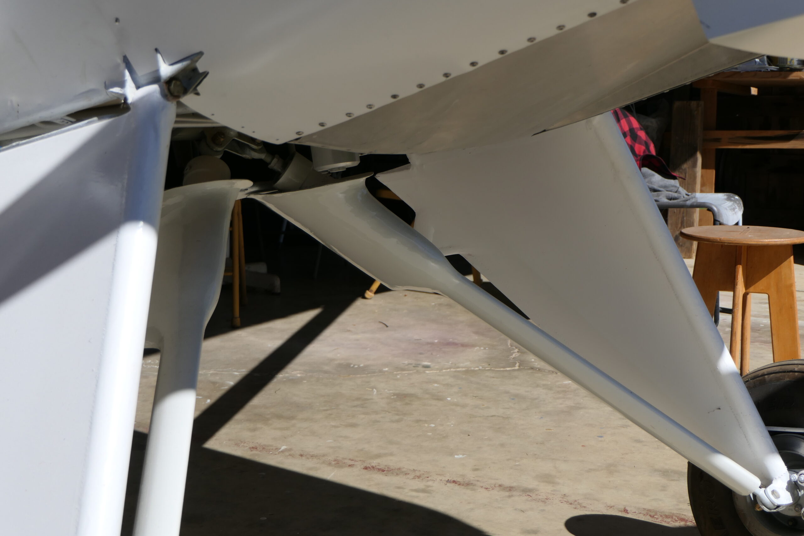
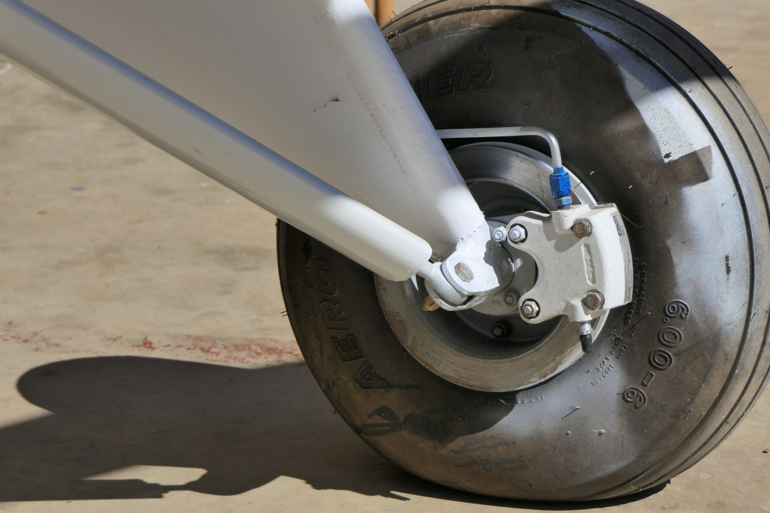
Builder Collin McDonald noticed some ambiguity about the hardware to use when securing the round tailwheel spring to the fuselage, and made a post on the forum to seek clarity. Should those be AN5 or AN6 bolts? 
Bob says, “We’ve used 5/16 and we’ve used 3/8 bolts there, and we’ve never had any problems with those bolts. We’ve used 5/16 on the lighter planes and 3/8 on the heavier planes.” Bob has used 5/16 bolts there on his own planes, and adds, “That stinger is hardened steel. It’s a really big job to drill those out. You don’t want to have to do that.”

Weight Savings with Composite Floorboards and Door Skins

Source: 2025 Q4 Beartracks, Bob Barrows
I have made and installed lighter weight door skins and floor sheets. Instead of using aluminum, I used carbon fiber and Kevlar. For the floor, use Kevlar layup, to about the same thickness as the aluminum call out. For the door skins, use carbon fiber about .025 thick, 2-3 layers. Lay up by using a sheet of .032 aluminum, about 2” larger all around than the panel needed. Apply three coats of wax to the face. Apply epoxy resin, lay first layer of cloth on wet resin, then apply a little more resin. Apply the next layer of cloth and poke it with a stiff brush until the cloth is a little wet from the underlying resin. Scrape the extra resin off to the sides with a plastic Bondo spreader. These panels will be about 1/2 the weight of aluminum.
I use the West System resins, selecting the slower variant (206) if I’m going to be working in hot temperatures, or the faster variant (205) for colder temperatures. A good starting point for these materials is Aircraft Spruce Part Number 01-01665 for the Aramid (Kevlar), or Part Number 01-01232 for the carbon fiber.
The West Systems epoxies are sold in various kit combinations starting with Part Number 01-08100 through 01-08400, depending on the size of the can and the hardener type.


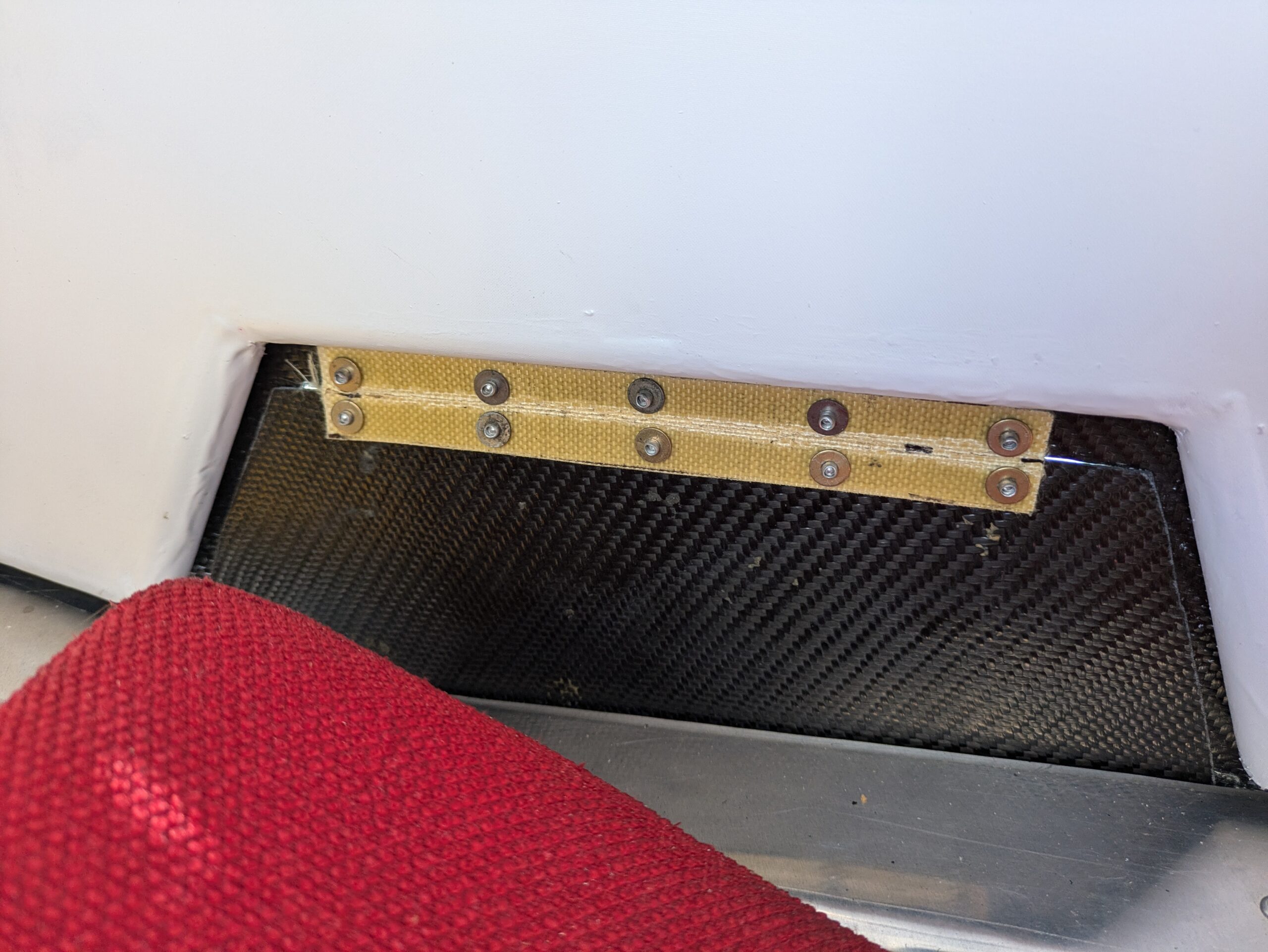
The photo below shows the Kevlar hinge on the mouse door. This is a scrap piece of the same material in the floorboards. I start with a rectangle, then bend it in a brake to about 90 degrees. This breaks the plastic resin but the Kevlar fibers remain. It has a natural spring-back action and is good use for what would otherwise be waste.

Thermoforming a Custom Skylight

Source: 2025Q2 Beartracks, Paul Gyger
When considering a skylight for my Bearhawk 4-Place, I had the usual difficulties and decisions, all mentioned in various threads of the Bearhawk forum. I remember reading somewhere that shaping the skylight proved difficult, mostly because the Bearhawk has 2 contours, one for the shape of the wing, and another perpendicular to the wing for the “Bearhawk bump”. This bump is required due to the elevator trim wheel, and if it is to be removed requires significant modifications to both the trim wheel and the stringer supports. Somewhere in the vast history of the forums I read about the process of thermoforming plastic, and so my long journey began to form a plastic skylight that followed the natural shape of an original Bearhawk 4-Place. The driving force of the experiment was that if the plastic was contoured it might solve two problems. First it would keep the original shape and avoid rethinking the trim wheel, and second I imagined that shaping the plastic would lend strength to it while reducing stresses from forcing it around curves. Time will tell.
Like so many of these side projects or modifications, if one sat down and responsibly made an estimate of the time and resources required for these fanciful substitutions, no one in their right mind would even consider them. Somewhat providentially some of us are not burdened with accurate assessments of how long things will really take to perfect, or how much material we will burn through in the process. It was in that spirit that I set out to first make a form, then make an oven, and then thermoform my skylight.
Thermoforming plastic can happen in a number of ways; vacuum molds and pressure molds both with weights and with air pressure. In the case of the Bearhawk a relatively simple drape type mold would suffice, basically just a copy of the natural shape of the surface in question. I accomplished this with plywood ribs that were held in place with a light frame that could then be removed and transferred to a base sheet of MDF. The voids between the ribs were then filled with whatever wood scraps were lying around the shop. The one exception to this is where the curves were only in one direction, say the center portion of the skylight. I was able to use a flexible plywood product meant for going around curves. Two examples of this product are Flexyply and Wigglewood.
The form was then covered with an old, mostly cotton bed sheet to prevent scratches in the final product:

When using a drape type mold, some consideration must be given to how the material will be held down and made to conform to the mold. This doesn’t seem like a big deal until you actually try to form a part and realize that some parts of the skylight are stretching and some are contracting, and even though things are quite flexible and pliable, it still requires a significant amount of persuasion. When planning a drape type mold having proper generous edges that extend past the actual part dimensions is highly recommended, as well as having some type of nesting area or starting point where the hot plastic can be locked into place as weights and clamps are applied. A little extra time on the mold will go a long way in making a repeatable part.

While plastic can be thermoformed with local heat application such as a heat gun, infrared, or torch, using an oven to thoroughly heat the entire part is essential. Plastic that is heated locally tends to get a wavy look that is very difficult to assuage. So the building of an oven is really inevitable, and anyone that is embarking upon this process must include this in their “time and resources” balance sheet. The design of such an oven is relatively simple, a large structure that is able to withstand heat and is insulated in some fashion. I used scrap metal to make a frame, I covered that with scrap sheet metal, and then insulated that. My heat source was two stove top burners sourced from Amazon for $30, a thermocouple and temp control unit. Now there is one design feature of the oven that is critical, it must allow the piece of plastic to stand vertically. Adapting a horizontal oven, ie the local pizzeria’s oven won’t work. There is a bit of an art to fine tuning things as far as placement of the burners and the thermocouple etc. I found that burners at the bottom worked best, with a piece of sheet metal separating the burners and the plastic. I did have a significant temperature difference between my oven floor and the top, around 10° C. I think this could be mitigated with a fan to circulate the air but I had success without. I used two metal tubes to clamp my plastic at the top, which allowed it to hang unimpeded. I won’t step into the debate of Lexan vs Plexiglass, but I will say that Lexan (polycarbonate) was significantly harder to work with. This is probably due to poor oven design, poor temp variation control, and inexperience on my part. Both of my attempts at making this part from polycarbonate failed. Lexan must be heated to a higher temperature, which exacerbates problems with oven design as a temp differential will be greater with an oven that is working harder. Another problem with Lexan is even though it’s hotter when forming, it cools faster, necessitating a fast transfer from the oven to the mold. After I built my oven I had some scrap acrylic that I used as a practice piece to test the oven and get a feel for things. This acrylic proved much easier to work with. It requires less heating (145°C vs 175°C for Lexan) , it cools slower, and it just seems to be much easier to work with for an amateur. Lexan also requires a drying phase to get the moisture out which is really quite long- for my piece it was 6 hours. Acrylic can be heated to temp without this drying time.

Eventually the time comes, the mold has been made, the oven is at temperature, and the plastic is ready. Nothing left to do but get everyone in the house fitted with welding gloves or oven mitts and bake some parts. I found that after about 25 min in the oven with a temp set to 145°C my plastic was just the right blend of pliable and able to take shape, without it being too molten. When a piece of acrylic is heated it will first bend or rise, this is a natural occurrence and it means that your plastic is not yet at temperature. A little more heat, or just a little more time baking and that curve or rise will settle down and the whole piece will be perfectly flexible. Going much past this temperature isn’t a great idea as it opens you up to deforming wherever weights or clamps are applied. It is a sweet spot, I found mine at 145°C.
Small deviations in adherence to the mold shape can be touched up later with judicious use of a heat gun. Great care must be taken as this local heating can give a distorted look. I had a couple small areas that raised up a bit as they cooled, but I was able to use the heat gun and get them proper.
In the end my acrylic skylight was a success. I have a part that follows both contours of my frame almost exactly. My skylight is under no stress from bending, actually quite the opposite it has added strength from the bending reinforcement. The view through the acrylic is almost perfect, I did end up with a few slight waves but they aren’t really noticeable unless you suffer from the OCD only a fellow builder will be racked with. Ultimately I decided to make two skylights and keep one on the shelf for the inevitable replacement required down the road.

Carbon Fiber Door Construction Using 3D-Printed Joints

Source: 2025Q2 Beartracks, Matt Clark
I wanted one-piece gull-wing style doors similar to what Virgil did on his BH5. I considered welding the window and door sections together or building from scratch out of steel, aluminum, or carbon fiber. I wanted to use square tubing to make attaching the plexiglass and sealing the edges easier. I’m better with composites than I am with TIG but my initial problem with the carbon fiber idea was how to make the corners strong.
When looking at carbon fiber tubing online I found some manufacturers sold corner inserts at normal angles like 45 and 90 to make strong epoxied joints. So, I figured I could 3D print corner inserts like those at whatever angles I needed and then wrap the corners with another layer of carbon fiber to make a very strong joint. I used 3/4 square 0.045 wall thickness CF tubing (Dragonplate from Allred co.) and 3D printed corner inserts using ASA-CF filament. The ASA is good with epoxy and the CF infusion makes it stiff and dimensionally stable. I created a 3D model in Solidworks for the corner insert and printed a few (many!) prototypes in cheap PLA or PETG. The top two corners are the easiest because those 3 pieces (top, upper front, and rear) are in the same plane. I measured each corner angle and printed those top 2 prototypes first. I had to print a few versions to get the angles just right. To get the angles perfect on the CF tubes I cut with an abrasive wheel and then sanded to fit.
1. Prototype Corner Insert:

2. Checking Fit

3. Fits Good

Once I was happy with the fit, I printed the corners out of the ASA-CF. I had to adjust the dimensions of the CAD drawings to get the ASA-CF part to fit snugly compared to the PLA or PETG. I epoxied those top 2 corners in place by clamping them into the door openings with approximately a 3/16 gap all around.
Top 3 Pieces and Hinges Tacked:

With those 2 corners secure I next worked on the hinges using 3/8” long sections of 3/16”ID stainless tubing on either side of the fuselage hinge tube very similar to the window hinge design. The stainless barrels were epoxy tacked in place. I used a clear 3/16 PETG plastic rod through all the stainless to keep them aligned during the glue up. I did have to adjust the hinges on the frame to provide more standoff to clear the square tubing and reinforcement CF (two photos below). I cut the outer welds, bent the barrels down slightly and then re-welded. I used a 3/16 solid brass rod through both hinges to keep them aligned while adjusting.
Hinge Outer Welds Cut:

Hinges Adjusted and Welded:

Once the SS hinge pieces were tacked in place on the top CF tube, I used epoxy with micro bubble filler to smooth the hinges out before wrapping them with carbon fiber.

7. Micro filler epoxy:

8. Sanded Smooth and Painted:

9. Unwrapping Hinges:

To wrap the hinges, I used 3 wraps of 3k carbon fiber, peel ply, and flow material. I then tightly wrapped the whole joint with electrical tape working from the middle out and let it set for the whole curing process under a heat blanket. The electrical tape wrap is a good way squeeze the excess resin out into the peel ply and flow material for a part that is difficult to vacuum bag. And the vinyl tape doesn’t stick to epoxy. The lower doors are a little more complicated as the front lower piece is curved and creates a compound angle at the 2 lower joints. For the curved lower pieces I clecoed a piece of .025 aluminum to the lower front door former and used that to trace the curve onto a piece of ¾” MDF. I cut kerfs into the inside of that piece without cutting through the 4th wall and bent it around the MDF form to glue the kerfs shut. Then I wrapped and vacuum bagged those pieces.

10. Lower front piece bent around form. The cuts are on the gold lines through only 3 walls:

11. Vacuum bagged lower pieces:

The lower corners have to allow for a slight twist to allow the square tube to be parallel and flush to the bottom former, so one leg of the bottom corner inserts is round to allow the bottom tube to be on a slightly different plane than the lower front. The round section isn’t as strong because it’s less surface area to epoxy, but that lower front corner will get a lot more reinforcement to mount the door handles there.

12. Final corner inserts for the lower 3 joints in ASA-CF:

13. Epoxy for lower corners

Once I had it all aligned perfectly in the door opening, I epoxied all the corners with the doors clamped into the openings just like I had done the top three pieces.

14. Curing in place within door formers:

15. Corners reinforced:

After the inserts cured, I reinforced each corner with an external wrap of carbon fiber using the same technique as the hinges, with the electrical tape compression. Once I figure out where exactly to mount the gas strut to the front upper tube, I’ll add 1 more wrap from the front hinge all the way to the gas strut attachment. To seal the front, bottom, and rear edges I’ll wet layup carbon and Kevlar around the edges just like Virgil did. Those pieces will extend ½” inside the frame to provide the lip for securing the window pane. This will also strengthen and stiffen the whole assemblies. To seal the top, weatherstrip will get squeezed between the top tube of the door and the fuselage tube as it closes. The lower front corners will get reinforced further to mount the door handles which will be the same as Virgil’s with the Z linkage to pin the front and rear. I’m planning to use a single pane of 3/32 Lexan for the windows. My door frames weigh 0lb 13oz compared to 4lb 14oz for the steel frames. Yes, there is more weight to add with the handles, windows, seals etc, but all those things get added to the steel frames too.

Winter 2024 Update from Bob Barrows – Companion Progress

Source: 2024Q4 Beartracks
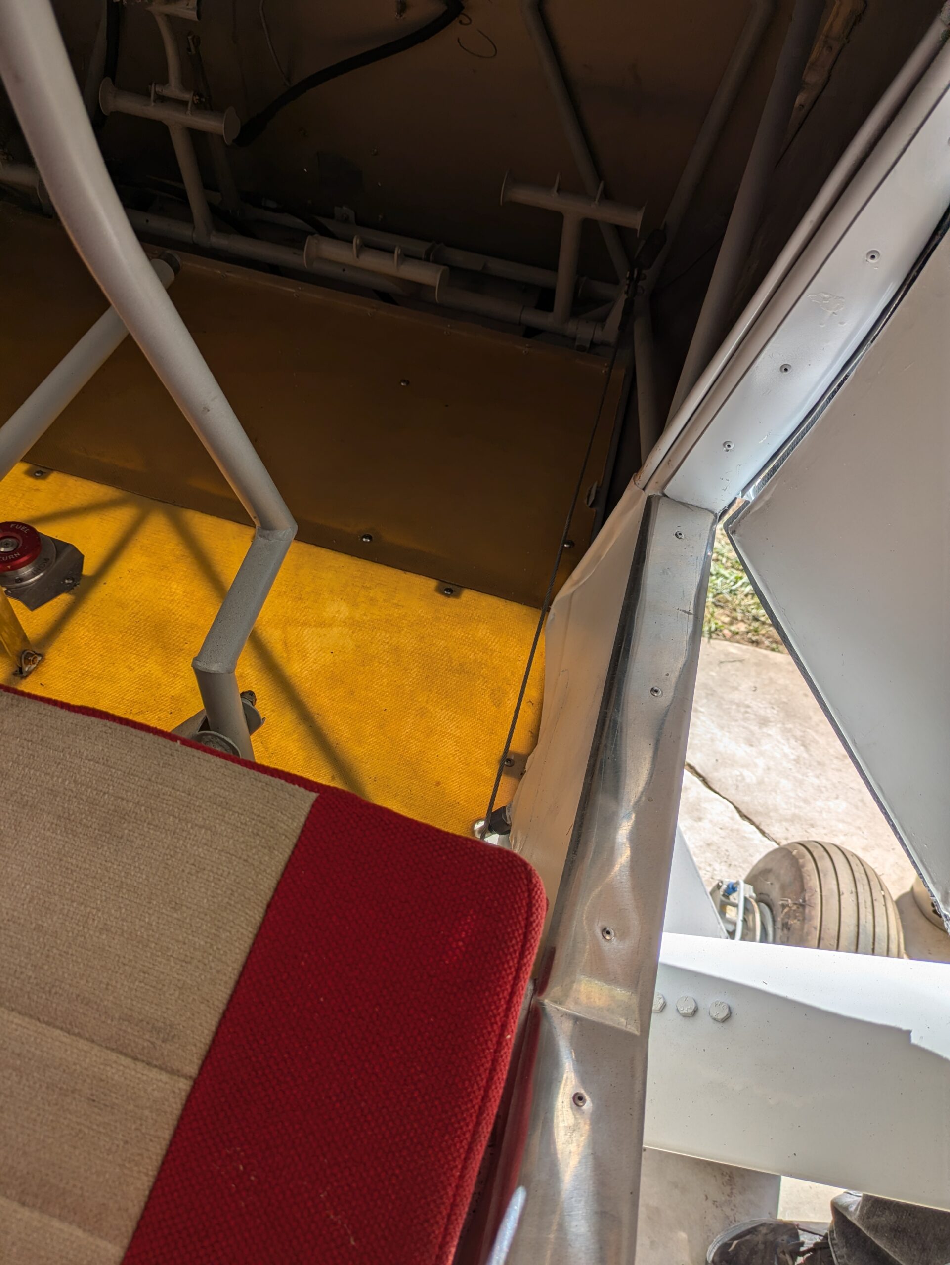
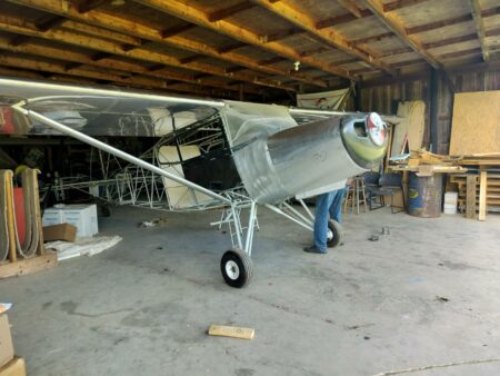
Bob’s Bearhawk Companion is looking more and more like an airplane. During our October visit, the weight was 1010 pounds, as pictured. In November, Bob broke some bones in his foot, and that has limited his shop hours. Thankfully the cast was removed a few days ago and in the coming weeks he can rebuild strength and spend more time in the shop. He is currently working on the exhaust and baffling. I asked whether he used a kit for baffling, and he said no. He enjoys the challenge of making a custom baffling set for each installation, and is also somewhat particular about how he wants it to turn out. He says, “When you already have an airplane to fly, it doesn’t matter that it takes a little longer.” He enjoys building things and likes the rewarding feedback that comes from consistent input to a project. There is fun and a sense of accomplishment in seeing it come together. The new Companion has several interesting features including Kevlar composite floorboards. Their translucence is displayed with the belly pan removed. The door skins are carbon fiber, and the mouse door hinge is a strip of Kevlar layup.

Summer 2024 Updates from Bob Barrows

Source: 2024 Q2 Beartracks
Work continues on Bob’s Companion project. As of press time he did a preliminary installation of the wings and has mostly completed the cowling. There is a mock-up engine that has no cylinders in place, and he has validated alignment and positioning of the engine, and is quite pleased with the kit’s conformation to the plans. The ailerons, flaps, rudder are covered, and the elevators and horizontal stabilizer are in progress. With the mock-up engine in place, the weight was 767 pounds. Bob feels like he is on track to meet the target empty weight of 1050 pounds. This build uses carbon fiber door panels instead of aluminum. Bob says it saves a little weight, and he’s pleased with how the carbon panels flex, drill, and otherwise behave much like aluminum would. To make them, he starts with a flat sheet of aluminum. He says you can also bend the aluminum if you want the part to also be bent. He applies lots of wax to the aluminum, draws out an outline of the rough shape of the panel, and paints resin onto the panel. Then he lays 2-3 layers of carbon onto the panel, and the next day, it’s ready for cutting to shape and installing. He made similar floor boards out of Kevlar, and figures those are 2/3 to 1/2 the weight of aluminum in the same application.
Bob and Diana recently flew the Patrol to Pence Springs, West Virginia for a get-together that included around 30 airplanes. They have a nice long grass strip there. Diana’s improved mobility and health are great news. She’s always eager to ride along whenever Bob flies. He says he alternates between flying his Patrol and LSA, just to keep both active, and enjoys both equally.
He has not been working much on his electric Ultralight project. It is still pending a new motor controller to up the motor output from 230 to 300 amps. Bob did design and build a new full-castering tailwheel for it, to improve taxi handling. The new tailwheel doesn’t attach to the rudder for steering but is easier to maneuver than the original skid. Bob says back when he flew his RV3 the tailwheel could either be swiveling or steerable, so he usually left the chains off and allowed it to swivel so that he could turn around more readily at the end of the runway.
Bob has been working on a solution for the Brake master cylinders that uses an EDM (electrical discharge machining) machine to make very precise fluid passageways inside of the bore. The EDM machine is well-suited for this kind of work and yields very smooth and precise shapes down inside the bore, based on the shape of a custom electrode.
Save the date for Bob’s Picnic on 10/19/2024 at VA04!

Cabin Organization with MOLLE

Source: 2024 Q2 Beartracks, Tyler Williams
I like clean organized spaces. Well, at least I do in my airplane and in my kitchen. My truck, on the other hand, is a complete mess…always. It looks like I live in it, which sometimes I do. But not a lot goes on inside the truck that forces me to be meticulous about it being clean and organized. I sit, hold the wheel, throw the snacks in the center console and turn on some good tunes. My kitchen is a different story. My chef’s knife is sharp, my spices are stocked and I am a stickler for “mis en place.” When everything is in its place, I can work efficiently and get into a flow to create, improvise and make great food.
Operating the airplane is a similar experience for me. I like everything in its place, the plane prepped and my mind sharp for the task at hand. Flying a plane, at least the way I do it, involves much more than road tripping in the truck. I don’t just get in, hold the wheel and follow the line on the map. From the preflight, to the engine management, to flying the terrain and improvising the route around weather and airspace, to chatting with ATC and jotting down instructions, there’s always something to do. An organized cockpit helps keep the mind free for the important things, and I don’t like anything flopping around loose. When flying far, I need water, a bag of snacks, sometimes a pen and paper, sometimes I need my flashlight, I’ve got my InReach on and I like to plug in my phone for music. I keep a lot of stuff in the back of the airplane too and it all needs a secure place to rest. From the basic things like a screwdriver, fuel tester and a small flashlight that get used every preflight, to the just-in-case tool kit, spare fasteners, tubes and patches, to control locks, tie downs, travel chocks and a first aid kit, I like to have what I need, when I need it. You can usually find help anywhere in the lower 48, but it sure is nice to have what you need to handle things, in flight and on the ground.
When I finished the Bearhawk and started venturing across state lines, I kept all the tool kits and spares in a duffel bag in the baggage area. But, digging through a bag of stuff to find what you can be annoying at best. For the cockpit items, I initially used the side pockets installed by my feet and the seat back pockets to stow checklists, small items, snacks and water bottles. But we travel as a family often and I like to keep those seat back pockets clear for my kids to stow their drawing paper, books, cards and such. My side pocket is best kept minimal so I can get my checklist or writing pad without fumbling around down there while trying to fly and my wife likes to have her side available for her magazine or book.
I got some inspiration from some nice overland camper trucks that used the MOLLE (Modular Lightweight Load-carrying Equipment) system to organize gear and tools. I saw seat-back MOLLE panels with small pouches and also some nice tailgate MOLLE panels for easy access to tools, even when the truck is loaded with gear. That seemed like the perfect solution for my plane. Our doors are all recessed slightly from the interior so there’s a little space there that can be used to hang a MOLLE panel and install some organizers.
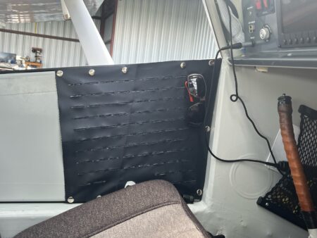
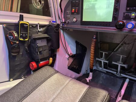
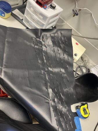
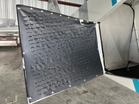
I made mine out of PVC coated Cordura nylon. I found some basic dimensions for the standard laser-cut Molle grid, drew it out on the fabric and simply melted the slits with a soldering iron. Mine are 1.12” wide slits, spaced ¼” apart horizontally and 1” apart vertically. I probably don’t have the exact military spec, but it was easy to lay out and fits all the attachments well. Someone more digital savvy could do the layout on a computer and have the fabric laser cut for a faster and more precise, factory looking result. I installed snaps in the door frames and fabric and snapped on the panels. They are lightweight and work great. Up front, I have my water bottle holder, sunglasses, pen, charge cord pouch, a place to keep my phone and snacks and my fire extinguisher secured on the door for easy access and still have all the elbow room I need. The passenger door has a panel as well with the same drink holder and stuff pouches and my wife loves it. The big panel on the aft baggage door stores my first aid kit, gust locks, travel chocks, extra quart of oil and funnel, preflight tools, hanging luggage scale, spare fuel cap, pitot cover, etc. etc. You can certainly stuff all these things under the back seat and that works just fine. But it sure is nice when the plane is fully loaded to be able to just pop the baggage door open and grab what you need.

DIY Seat Upholstery

Source: 2024 Q1 Beartracks, Mark Richardson
Those of us who are building (or have built) an airplane know that there is a lot to learn over and above being a pilot. Leaving aside manual skills, we need to learn about the rules and regulations for building and licensing, avionics and electrical design, AC-43.13B contents and how to actually do … stuff … correctly, it’s the manual skills that are the bread and butter of aircraft building and the most fun.

With all models of the Bearhawk you need to learn how to rivet (both solid and pop), work metal (bending, forming, filing, etc), do fabric covering, run cables, install the engine, fit and prep fibreglass, cut, trim, and fit plexiglass, and a plethora of other detailed skills. If you are brave (stupid?) enough and decide to scratch build, you also need to learn to weld, operate metals shears and brakes, build and align jigs, and so on. There are lots and lots of jobs and skills you will learn by building an airplane.

A couple of the jobs that are often farmed out to the pros are aircraft painting and seat upholstery. I had already learned to paint an airplane when I built my RV-8 20 years ago (Google C-GURV) so although I am using a completely different paint process this time (Stewart vice Imron), it wasn’t totally new.

Which brings me to the purpose of this short article; how I upholstered my aircraft seats (your mileage may vary, batteries not included). I had considered (very seriously) just buying upholstered seats and carrying on. However, three things made me change my mind: 1) this would be a new skill that might be fun to learn, 2) I’m now retired so I have time, and 3) OMG it is expensive to have seats professionally done! I won’t lie, I found this the most challenging thing to learn yet. But it was actually fun and I am, well, not richer, but certainly not poorer by hundreds of dollars by doing it myself. I can’t give a step by step how-to with measurements and detailed instructions otherwise this article would be book length. However, I will show a bunch of pictures with descriptions of what is happening and notes on things to think about and avoid. Yes, even you can learn to do this.

The tools and materials:
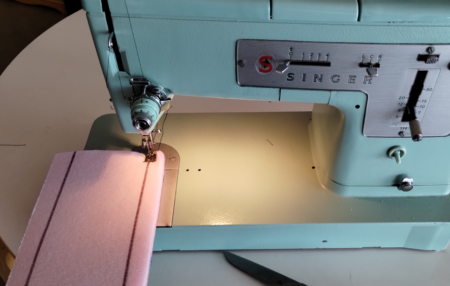
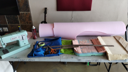
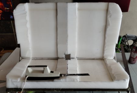
We have a 60 year old Singer sewing machine that we bought fully restored a couple of years ago. No fancy computer features but it is indestructible and works great. You’ll need pinking shears for the fabric, regular scissors for the foam, sewing clips, rulers, marking pens, paper/cardboard for templates, tape, spray contact cement and a work surface. I used an electric carving knife to carve up the foam for the seat parts.
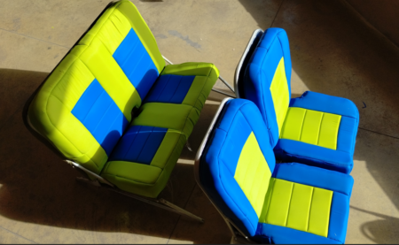
For the fabric I used RipStop because it is quite inexpensive, is super tough, it won’t give me third degree burns on a sunny day like leather, and actually looks really good. You’ll need some backing foam (1/2” or 1cm) that has a backing material on it, and foam for the seat bases and back. I got the Confor Foam seat bases from Aircraft Spruce for the front seat bases and used 2” firm upholstery foam for the rest.

The Method:
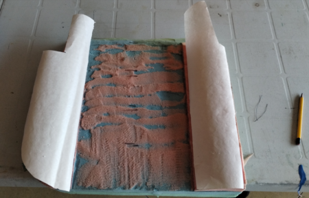
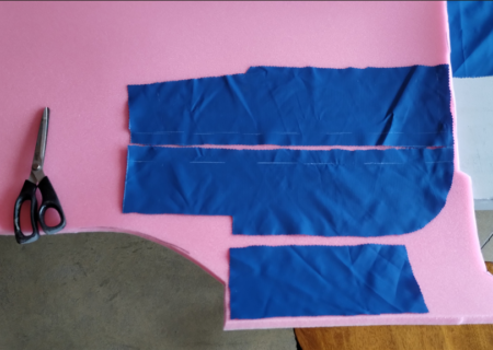
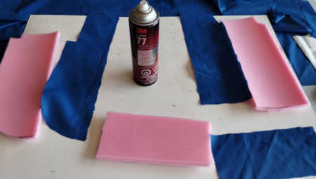
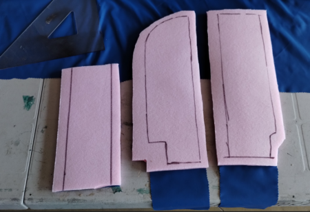
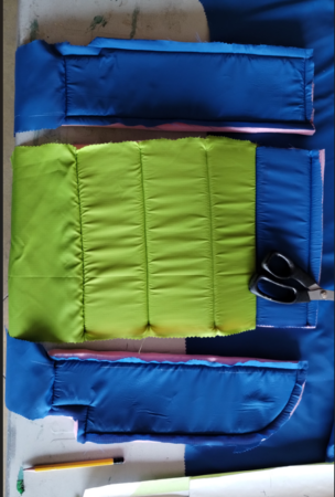
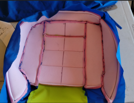
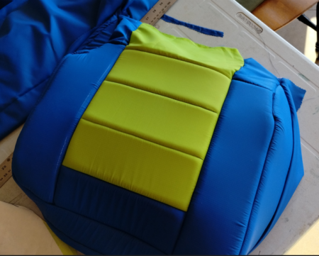
I made templates out of paper and cardboard for the various components of the seat cushions that were then used to cut out the fabric, backing foam, and to lay out the sewing lines. After a LOT of trial an error (mostly error), I added 3/4” on all sides to my fabric and backing foam patterns and just snipped off the excess at the end. Once the fabric pieces and backing foam were cut out, I used spray contact cement to apply the fabric to the foam (this is temporary to keep everything in place for initial sewing). I then used the paper template to mark on the back of the foam where I wanted to sew. Again, trial and error taught me to sew with the fabric side down as the feeder foot (or whatever it is called on the sewing machine) worked way better this way.

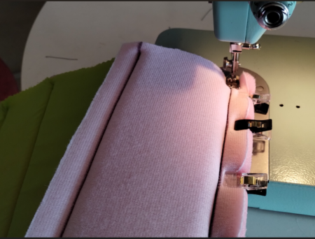
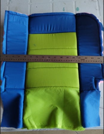
Once you get the various individual parts made you need to put them together. The trick is to overlay the existing sewn seams on the two sides such that when you sew the pieces together the seam disappears. Use LOTS of clamps. I put an extra 2” of material where the fabric would wrap around the back of the seat so there is material to pull on to tighten the fabric then staple. I used 1/4” birch ply with lightening holes as the backing material and stapled the fabric to the ply. The ply is quite light, and since the RipStop weighs almost nothing, the seats are not at all heavy. I will use Velcro to attach the seat components to the actual seat frames.

I realize this is hardly a “this is how to do it” article, but I hope it is an encouragement to try it yourself the next time you need seats for your airplane. The most expensive part of the whole thing were the Confor Foam seat bottoms ($200 CAN each!!). The rest was very inexpensive with the RipStop material < $5/running yard. Our own Michel Roy is the one who inspired me to do this with the seats he made for his Bearhawk using RipStop and between looking at his pictures and watching a BUNCH of YouTube videos, I was able to produce these:
Cargo Belly Pod for the Bearhawk LSA

Source: 2023 Q1 Beartracks, Michael Swain
Nestled on a private airstrip in North Central Florida is Jerry Cornwell aka. “Stinger” and his scratch-built Bearhawk LSA. Jerry has many aircraft builds under his belt including a Boredom Fighter and Van’s RV8, and has been working around aircraft his whole life. Back in the day he could be found maintaining F-4’s for the Air Force including time with The Thunderbirds. Stinger began the Bearhawk project around 2015 when he decided he wanted an LSA. Having an airplane that he could teach his grandson how to fly was one of the factors that led him to the Bearhawk. 3 years later on February 25, 2018 the LSA flew for the first time. Fast forward to today and Stinger has put over 320 hours on the plane of which his grandson James, now 16 year old has close to 175 hours flying the Bearhawk LSA.
The LSA can carry much more than it can fit, so Stinger set out to build a belly pod. Being able to haul camping gear for 2 was the main reason to build the pod he tells me, but I think Stinger just needs to be building “something”. The general design is 2 structural bulkheads skinned with .025 and .020 attached at station C & D with doubled up ratchet straps. The project started with 2 cardboard templates of the general shape, these “bulkheads” were then cut from .025 aluminum. Some hardware store .125 aluminum angle was then fitted around the perimeter of the bulkhead, c-clamps were used for mockup but eventually riveted. The spacing between bulk heads was accomplished by making some 1 inch flange angle from .040 5052 and matching it to the lower longerons. (All material except the .125 aluminum was left over material from the LSA build.) Some “hat” style stiffeners were made from .040 5052, similar to what is used in the fuel tank bay on the Bearhawks. Two of these run side to side under the bulkheads and one of them runs longitudinally down the center section to provide stiffness to the skin. The ratchet straps run through the the stiffeners that are placed under the 2 main bulkheads. The center section of the pod is skinned in .025 and the fore and aft sections use .020. .040 5052 angle is used along the lower bend lines where the skins transition from horizontal towards the lower longerons and along the top edge of the skin and the flanges are used later for weather stripping. The forward section stops about 1/4 “ from the cowl and the rear section extends about 20 inches aft of the rear bulkhead. The whole thing is riveted together once the fit is just right. After riveting, the center of the solid bulkheads were cut out and a door was installed. Some hardware store .125 aluminum bar was used around the door opening and piano hinge for the lower edge. Flush cam type fasteners were used to secure the door, similar to what is used on many cowls. Some 1 inch wide weather stripping is used around the mating surface and the 2 points on the bulkhead were potential contact would be. The pod is attached using 4 ratchet straps, 2 in the front and 2 in the back. They come together under the front seat and back seat. The straps used in testing are rated at 500 lbs working load. The pod weighed in at 11.2 lbs. and no measurable airspeed changes were noted in flight testing. Also, no handling differences were felt by Stinger or his grandson. Now all that’s left is to load it up and go camping!
Cardboard Template:

Bulkheads mocked up with angle:

Interior Details:

Skinning the Center Section:

Skinning Complete, and door installed:

Painted and strapped on:

Making the Rear Left Window Removeable

Source: 2022 Q1 Beartracks, Jay Townsend
Firstly let me say I am not a “handy DIY” type of guy. I undertook this project as a complete novice.
There are probably easier planes to build, but none had the flying envelope of the Bearhawk, so it was an easy choice for me. I am very lucky to have a mentor who has built both a Rocket and a Carbon Cub along with all his tools. My local airport, Heber City, can easily be called a hot bed for experimental builders so I have a great group of guys to lean on for advice. That being said, the rear windows on the
Companion had us all baffled.
Most things building up to this point (getting ready to cover the fuselage) have been pretty straight forward. Ok, I may have called Mark a time or two! Rear Windows have been confusing. We collectively had a lot of discussions which resulted in a lot of head scratching. In the end both Bill (my building mentor) and I came up with a very similar plan the same evening, which is amazing as this had been analyzed for a good 2 to 3 months. I had sent Bill a text early one morning telling him I had figured it out, he texted back that he was looking forward to hearing the solution as he had an idea too. I was planning on installing and gluing in screws from the
outside of the outer frame, to allow the window and inner frame to be attached after covering. Bill had an odd look in his eye as I explained it. Turns out he had a very similar idea, but with a better solution for attaching the inner to the outer frame.
So here ya go, this is how I solved the problem. To begin with, I really wanted the window frame inside the door former, but this makes a potential window replacement without cutting into covering very difficult. First I drilled out the factory rivets to separate the inner and outer frames. I bought 70 Clickbond studs, #CB5000, but they are round, so I had to grind each one to allow the window to fit into the window channel (photo of the modified stud below).

The flat plate portion of the stud is adhered to the inside of the outer frame with special adhesive, creating threaded studs protruding into the cabin. The inner frame is attached using these studs, forming a sandwich with the window plastic. I used denatured alcohol to clean the frame and the back of the stud for bonding using the proprietary Clickbond adhesive that is super strong and fast-acting. Next I put down cling wrap on the inner frame and pushed the studs through the cling wrap. This protects the inner frame from the adhesive. This was Bill’s idea and a brilliant one to keep things nice and clean (photo below).

I put the Clickbond adhesive on the stud backs. The Clickbond adhesive is amazing and sets up in less than five minutes, so it is not really possible to do all the studs at the same time, so I did 1/3 of them at a time. Then I put the outer frame on very gently so as
not to mess up the orientation of the flat sides of the studs, and used clecos and clamps to allow the inner and outer frames to be perfectly matched (photo below).


I also used Knipex “Pliers Wrench” pliers (part number 86 03 250) to align the inner and outer frames perfectly by squeezing the edges so they align. These pliers are the perfect tool as the jaws move parallel to each other, squeezing evenly rather than on an
angle like conventional pliers. This is crucial in my view as you want the studs to line up when the inner and outer frames are aligned.
I also used JB Weld on the top and bottom of the outer frame to allow it to be riveted to the door former while remaining parallel to the door former. Otherwise the joggle of the outer frame would cause it to be at an angle.

I will attach the outer frame to the tabs on the fuselage with solid rivets. I will have to drill the inner frame to allow for the shop head of the rivets. Next I will cover the interior cargo area and glue the fabric to the inside of the outer frame. Then I will cover the fuselage and wrap the fabric over the outer frame, and glue the exterior fabric to the the inside of the outer framer. This will allow me to install, but more importantly in the future, to replace a rear window all the while having nice clean lines of the window frame inside the door former. I will be using acorn nuts to hold the inner frame in place.
This method also makes sliding the window into the channel a non-issue. There have been multiple threads on the Bearhawk forums about the difficulty of sliding the windows in the window frame channel. This also allows you to determine the thickness of the “glass” rather than the channel dictating the thickness you can use, personally I will definitely use a slightly thinker window than the original
frame channel would have allowed.
I know I spent a LOT of time trying to come up with a plan that was pleasing to my eye, hopefully this will save others time contemplating a plan and make life easy should I need to ever replace a window. I am trying to think of anything down the road that may need to be done and how I can best set up the plane during the build process to allow for the needed maintenance.
Editor’s note– Bob likes to slide the window in from the front, but says folks are always free to innovate!