Source: 2025 Q3 Beartracks
N789WM first flew on August 5th, 2025. You can read about my experience with the first flight of my newly built Bearhawk aircraft, following my transition training in North Carolina, on the Bearhawk Forums. In summary, despite careful preparation, the initial attempt was aborted due to a fouled spark plug, and the actual first flight revealed a misconfigured RPM sensor, leading to false high-RPM readings and considerable anxiety mid-flight. Minor issues like a lost fuel cap and unfastened tailwheel chains were discovered post-flight, reinforcing the importance of a thorough punch list and better planning. Ultimately, the flight was successful and educational, and shows the value of preparation, clear checklists, and learning from unexpected scenarios.
Since that first flight, there has been ongoing maintenance, discovery, and tweaking. After the first couple of hours, I was struggling to keep my cylinder temperatures within a reasonable range, and having to level off and build speed to keep the rear cylinders below 430F. I was very concerned about glazing before the rings had a chance to seat on the brand new engine. After having a friend look over my engine, and baffles, we realized a couple things: My front air dams seemed too high in his experience; and I hadn’t ever really gotten back around to sealing all the holes in the baffling. He also has a O-540, but in an RV, and he said he ended up without air dams at all. He reasoned that if my temps are high, I could remove the air dams altogether and the worst case they are too low and I have to put some back. I agreed, and drilled off the front air dams.
Next, I set about diligently and thoroughly finding every crack of light shining through the baffles and sealing it with RTV. I prefer the gray RTV, as the color blends in well with the rest of my engine. This ended up using almost an entire tube of RTV. But I felt confident that this would help address the heat issue. The main is to get that pressure differential between the upper and lower engine great enough to pull air though the cylinder fins, and it doesn’t take much, but any hole in the baffling is lost opportunity to carry away heat, and pressurizes the lower cowl.
The next flight the CHT’s were much better, and increased much more slowly. Success! But now, the next problem…my oil cooler is front mounted with a scat hose leading to a duct over the cooler to put the air through it. Lots of gaps around the fiberglass duct against the face of the oil cooler. Get another tube of RTV…
I also struggled with high CHT’s around #5, and a common solution for this, depending on how your cylinders are cast, is to build an air duct to shunt air around the backside of the cylinder. This called for breaking out the rivet gun and some scrap aluminum and within a few hours I had a decent looking duct. This greatly helped even out the CHT on #5 to something close to the other cylinders.
My project was a stalled out project with a new engine that had been sitting for a number of years. I had borescoped the internals of the engine as much as possible, and it all looked pristine. However, in the last few hours, I have had a number of seals, O-rings and gaskets start to leak. If you have had your engine for a while, the internals are probably fine, but you should expect to go through a round of fly, find the leak, replace, fly, repeat etc. Many rubber and non-metal parts of an engine wear out over the years whether they fly 1 hour or a 1000 hours. This lead me to have a number of oil leaks, an intake leak, and a fuel leak, all within the last 10 hours. Nothing catastrophic, but annoying nonetheless.
Initially, my flight controls felt very “heavy” and the adverse yaw was over the top. Thanks to the forums, and some posts I found there, I decided to go back through my tail and take it completely apart and identify any source of friction. I found quite a few places that I could have done better the first time, and most of my friction was actually in the trim tab on the left side. The hinge would bind against the paint and the clevis pin was tight in the hinge. I sanded, reamed, polished and straightened the elevators relative to each other very carefully, and this removed almost all the friction in the pitch.
For the adverse yaw, I decided to check my aileron rigging again, and raised both ailerons about 3/8 inch reflexed, as many had reported this removed a lot of the adverse yaw. I also went back through my flap rigging and made sure they were exactly equal to the wing trailing edge, and got everything as straight as possible.
The first test flight after the rigging changes was noticeably better. Most of the adverse yaw was gone, but enough to still keep you on your toes, rudder-wise in the turns that is. My autopilot no longer complained about trimming while maintaining altitude much better. I still have a very slight right roll that I am hoping a little more attention to the rigging will alleviate, but if not, I will employ the “washer trick” under the heavy wing hinge.
I am thankful that we live in the experimental side of aviation, since it allows us to experiment and to have “experimental” avionics and tools to discover and address issues quickly and confidently. Without a good engine monitor, I would not have been able to tell exactly which spark plug had fouled on my first flight. Without continuous monitoring, I would not have realized that one of my CHT problems was a leaking intake gasket. I also want to emphasize how invaluable sites like the Bearhawk Forums, Savvy Aviation, and Flysto are if you are willing to share your engine and flight data. Using Savvy, I was able to analyze engine data and dial in on the intake leak. Using Flysto, I was easily able to identify pitot-static errors, and rewatch and critique my flying. And of course the Bearhawk forums are great for tips, tricks, and the comradery surrounding this excellent airplane type.
As of the evening I am writing this, I am at 17 hours, having a wonderful time flying, looking forward to seeing other Bearhawkers out there, and just found another oil leak.
First Condition Inspection Status Update – Crankshaft Seal Leak and Battery Overheat Mitigation
Source: 2025Q2 Beartracks, Paul Minelga
Last month I did my first condition inspection. It’s hard to believe it has been a year since I got my Airworthiness Certificate! As the months went by, I kept a running squawk list of items that needed attention, but weren’t safety of flight items. In addition to all the inspection items normally done on an “annual”, I took care of the items on the list and did a deep dive into the entire aircraft, from one wing tip to the other, nose to tail. I even cut open the EFII boost pump fuel filter (FF-2 Pre-filter) to see if there was anything in there as it’s a sealed unit. I found nothing inside, completely clean except for a tiny fleck or two. It was $48 for a replacement, but now at least I know what it looks like on the inside.
One thing that was a bit of a concern to me was the nose of the engine always seemed like it was just a bit wet. Nothing that I would consider a leak, but a tiny bit oil was coming from somewhere. I was doing the inspection in the hangar I did the initial assembly in. The mechanic that helped me along the way through the years suggested that I pull the prop to have a look at the nose seal around the crankshaft. He called it the “Lycoming runny nose”, as from his experience they are susceptible to weeping from that crankshaft seal. But, with only about 43 hours on the engine it shouldn’t be wet up there. At the time he was painting a customer’s aircraft wings and had time in-between coats to lend a hand, so we pulled the prop. The seal was intact. But, he could place a pick that had a 90 deg bend at the tip onto the seal and rotate within the bore! It was pretty unusual as the bore the seal rests in needs a sealant applied before the rubber seal is pushed into place. We were sure that we had done this on assembly, but the evidence suggests otherwise! The old seal was removed, bore was thoroughly cleaned, sealant applied and a new seal was pushed into place. After the post-inspection run-up we had a good look at the nose, and the dry case proved we had found the culprit.
I did install a K&P S15 permanent oil filter in place of the normal Tempest oil filter. I’ll report on that and how it works out in the future.
One embarrassing find was the elevator trim cable turnbuckles weren’t safety wired! On my BH they are inside the back of the fuselage, in front of the horizontal stab. I don’t even know how many people looked the airplane over in the previous 12 months and everyone had missed it. I’m not proud of the find, but I’m glad it was found and taken care of. I pride myself on being anal-retentive on such things, but such a simple thing being overlooked is pretty scary. Anyway, lesson learned and I hope as others look at their builds when they are getting ready to fly to triple-check everything.
Another discovery was the bottom of my EarthX ETX900 battery case had melted! I never had any issue with the battery and it performed great. I shared these pictures with EarthX tech support, along with pictures of my installation. They said it was probably too hot against the firewall and that caused the case plastic to sag where it wasn’t supported. They said to send it back and they would check it out. I did, and after evaluation they said the battery checked out fine. They would put the components in a new case and send it back. I got it back and it looked suspiciously like a new battery, at no charge! It does get hot at the firewall and I do remember when I was breaking in the engine, it ran pretty hot under the cowl. On one day last summer, after refueling on one of the engine break-in flights, I did get a battery temp warning light indication. That may have been the time when it happened, I don’t know. But it wasn’t easy to spot and the folks at EarthX were amazing to deal with. At their suggestion I fabricated a heat shield box for it, covered with Thermo-Tec 13575 aluminized heat barrier. I’ll fly with it for a bit and see what happens and determine if it is effective in preventing any thermal deformation of the battery case. If it isn’t enough. I’ll probably install a blast tube for extra cooling.
The last thing I did was install an AV-MAG magnetometer in the right wingtip for my AV-30s. The headings on both units are worthless without it. The installation went relatively well, but it took some doing. We had to use the wiring for the nav light to pull the magnetometer shielded wire and some lacing tape through the wing, and then used the lacing tape to pull the nav light wire back through. Moral of the story, maybe when the wing is open, leave a string or something in the wire path to help someone thread something through in the future. After the installation, I had to go out to the compass rose and calibrate both units at 30 degree increments. Since there were no lines connecting the painted compass arrows, it was impossible to get it accurately on centerline. I ran to the local hardware store and got some lime green paracord. I used a couple of heavy things to hold each end in place on the painted compass rose while I wrestled the BH into position. It was a royal PITA to do by myself. The wind was blowing and it was cold, but I did get it done.
If you are building, don’t give in, don’t give up. It’s worth it!
Fuel Pumps and Flow Testing for Big Engines with Carburetors
Big Carb Engines, Fuel Pumps, and Flow Testing, part 1
Source: 2025 Q1 Beartracks, Jared Yates
Back in early January I was departing for a short flight back home, when I got a fuel pressure warning on the takeoff roll. The EMS is configured to alert when the pressure drops below 3 or so PSI, because I have found that if I forget to turn on the boost pump, that’s about what it drops to at very high power settings. Usually the alert reminds me to reach down and turn on the boost pump, but this time, the switch was already on. When I got home, it didn’t take much testing to find that the little electric Facet cube pump had decided to retire.
This seemed like an easy thing to fix, the only question was whether I’d have to order a replacement or whether I might get lucky and find one at a local parts store. Little did I know, I was about to step into a rabbit hole that three months later I’m still not quite out of.
Our plane has a carbureted O-540, and larger carbureted engines are the only ones that share this problem. For folks with a carbureted 360, including ourselves when we had one, 3/8” fuel lines are perfect. They can provide around 30-35 gph, which is 150% of the required flow rate of the less-thirsty engine. For folks with a fuel injected engine, you’ll be using higher pressure pumps anyway, so the 3/8” lines are plenty sufficient, and this rabbit hole is moot. Some builders have been able to reach acceptable flow rates with 3/8” systems and big carbureted engines, especially if they don’t use a fuel flow measuring sensor, though I was not. Also, I really prefer to have a fuel flow indication for several reasons. It’s a great real-time diagnostic, it helps with establishing throttle/prop/mixture settings for various phases of flight, and helps with flight plan monitoring. An electronic system can keep track of how much fuel has passed through the sensor and provide an indirect fuel quantity indication and warnings. But the fuel flow sensors are all designed with tiny little passages, that make for a big flow reduction– much more on that later.
When we first acquired our current plane, it had an engine-driven diaphragm pump and the electric boost pump, which is a Facet 40108. I did a flow test to see if we could remove the pumps, but did not have anywhere close to sufficient flow with the fuel flow sensor in place, so I carried on with the pumps in the plan. The 40108 pump is handy because it has 37-degree flared fittings integrated into the inlet and outlet. The internal passages are the same size as the 3/8 lines, and it has no additional check valve or positive flow shutoff when power is removed. When I went to purchase a replacement, I found out that the 40108 pump had been discontinued. This shouldn’t be a problem, Facet has a whole line of pumps. Unfortunately, almost all of the cube pumps have 1/8” pipe thread fittings. That’s not going to work. The Vans builders have changed to the 40135, which has the right fuel pressure for a carb (nominally 5-7 PSI), but uses the 1/8” passages. It does not have a check valve per the specifications chart, though all of these pumps do have a natural check valve function and prevent reverse flow. There is a 40109 which has 3/8 pipe thread ports, but it has an extra effective check valve function. I ordered a 40135 and a 40109, and holding them on the bench, I could tell that the 40109 was not going to work. The check valve provided so much restriction to forward flow that I don’t think the gravity pressure was going to open the valve at all. The 40135’s natural check valve function was a little more stiff than my old 40108, which is 20 years older, but tolerable. The problem was just the tiny ports.

So if we were going to continue to use pumps, we had a few options. One would be to run multiple 40135 pumps in parallel. I considered one on each 3/8” line just upstream of the fuel valve, but there would be some serious drawbacks. Basically there would be no cross-flow capability between the left and right tanks, because the pumps are natural check valves. We could run two pumps side by side with Y or T fittings, in hopes that the flow rate between the two would be sufficient with the electric pumps off. I wasn’t confident that this was achievable, but also didn’t test it. Another option was to attempt to modify the pump, such as drilling and tapping new threads to increase the inlet and outlet size, or maybe destroying the check valve function of the 40109. I wasn’t confident that either of these would be successful, and even if they were, replacing the next broken pump would require repeating the mods.
The next option was to consider a fuel system redesign that would allow us to eliminate all of the pumps. I spoke with Tyler Williams about his installation, which is a carbureted engine bigger than ours, with no pumps. He found that by increasing the line size to 1/2” from the fuel valve to the carb, he was able to get sufficient flow without any pumps, though he was not using a fuel flow sensor. It makes sense– using 3/8” lines for single tanks, but 1/2” once they are combined. This was the most appealing option, but sometimes even a small change ends up big.
The first order of business was the fuel valve. Our plane was built before the Newton SPRL valve was available, so it had an Andair valve. There have been a few iterations of the Newton valve, and it is better now than ever before. The current version is actually Bearhawk-specific and is only available from Bearhawk Aircraft. It is manufactured so that the outlet is on the aft end of the valve, so that the fuel can flow aft/downhill to the gascolator. The SPRL valve has its own non-standard interchangeable fittings, with several different options available. Bearhawks with 3/8” systems can use Bob’s gascolator, which has 1/4” NPT threaded ports. The valve can be configured with 3/8 inlets for each tank, and a male threaded 1/4 NPT outlet which can be directly attached to the gascolator. This saves fittings and makes for a very clean installation. In our case we set aside the 1/4” fitting and ordered a 1/2” flared fitting, which is part number 05-04453 at Aircraft Spruce, for a pack of 3. Now all we had to do was defuel the plane, remake the two lines that bring the fuel to the valve (because the old lines were an inch too short) and redo the mounting of the valve to the floorboard. Glad I didn’t have any other plans for January?
We also needed to up-size the gascolator. The only viable option that I could find was from Steve’s Gascolator. They make two units with 3/8” NPT ports, and two different bowls. Height is important in the Bearhawk, because we are trying to fit the gascolator between the floor and the belly. The shortest combination from Steve’s was the SA3-10-B, which has a 3-ounce bowl. I used one AN822-8D fitting on the inlet side. This fitting has 3/8” pipe threads on one side and 1/2” flare on the other side of a 90-degree elbow. On the outlet side I eventually used the AN823-8D, which is a 45-degree version, because it did a better job of pointing the line where it needed to eventually get. If you are following along and ordering parts, the gascolator also requires a 1/8” pipe thread plug at the top. I used an aluminum Aeroquip FCM3685 though I did carefully file it down to be almost flush with the top of the gascolator housing, so that the gascolator could sit as high as possible. I made a u-shaped bracket out of aluminum left over from the instrument panel, which attaches to the floorboard with 3/16 rivets.
Going forward to the firewall, I increased the size of the existing AN837 bulkhead fitting to the –8, and that also needed one AN924-8 nut. These larger fittings are much more expensive, I’m noticing. Then I’d also need a 1/2” flexible line to go from the firewall to the carb, and a new fitting for the carb itself. The carb has 1/4” pipe threads, so something like an AN822 would be nice, except that MS20822 doesn’t list a fitting that has a 1/2” flare fitting and a 1/4” pipe thread. I found one at Pegasus Auto Racing, part number 3253-04-08. This fitting is aluminum, and I would prefer steel, but the carb itself is aluminum so I was willing to compromise. A 45 or even straight adapter could also work here, depending on how your line is routed. I have found that using a 45-degree fitting at the firewall and approaching the carb parallel to the thrust line helps keep the flex line from rubbing on the cowl and clear of the exhaust, but there are any number of good ways to get this done.
I didn’t have the where-with-all to figure all of this out with a single order. A few weeks and around $1000 into this project, what was there to show for it? I’m glad you asked. First, let’s talk about the flow rates, which means talking about flow testing. In the US, testing is not required by regulation. It used to be required for store-bought planes but it seems that requirement became less specific in recent years. Canadian builders tell me that the flow test is regulatory for their homebuilts. I decided that the test was important enough to comply with. I wanted to get 150% of the engine’s maximum flow rate. Past flight experience with this engine and prop tell me that I’d like to see 37gph in the test, in order to remove the pumps. With the new lines, and no fuel flow sensor, I ran some preliminary flow tests with the wheels all on the ground. (A proper test would come later, with the main wheels elevated.) I was getting 47 gallons per hour on Both. This is great! But then, I installed my old Flowscan fuel flow sensor in the flex line close to the carb, and the rate dropped to 32 GPH. This was not great. I had ordered an EI FT-90 Gold Cube sensor to try, and it increased the flow to 34 GPH, meaning there was still some work to do. Tune in next quarter for part two, getting to a successful fuel flow measurement.
A Corvair Engine for the Bearhawk LSA
Source: 2024 Q1 Beartracks, David Swartzendruber
I am building a Bearhawk LSA and one of the engine options for the LSA is a Corvair auto engine conversion. This is what I have chosen for my LSA and I completed my engine build at the end of 2023 during a 3-day supervised build in William Wynne’s shop in Florida. Bob Barrows and William Wynne worked together to design a motor mount for the Corvair engine in the Bearhawk LSA and this mount is available from William. But I’ll back up and start at the beginning of my story.
Like many of you, I decided I wanted to build an airplane many years ago, about 33 years ago for me. However, along the way I lost that dream when it didn’t seem like time or money would allow that to happen. About five years ago, that dream was rekindled when I picked up an unfinished non-Bearhawk project for a very affordable price that was designed to use a VW engine conversion. As I thought about what to do for an engine, I came across the Corvair and William Wynne’s website, Flycorvair.net, and began to consider using a Corvair engine in that project. Through the information on Flycorvair.net, I also discovered the Bearhawk LSA was a good candidate for the Corvair engine and I became less enthusiastic about the project I had acquired. I eventually decided to order a Bearhawk LSA kit and sell the other project.
Having already started down the path of building a Corvair flight engine, I thought I would go ahead and complete that while I waited for my LSA kit to arrive. The first step is to get a conversion manual from William Wynne. This manual includes information about which core engines can be used to build a flight engine. I picked up a 1965 Corvair parts car for $250 and the engine from that car became my core. Corvair flight engines always start with a 1964-1969 engine because engines earlier than that had a smaller stroke, lower displacement and lower strength crank and rods. My core engine was locked up, but I was still able to disassemble it and discovered that the piston rings on one piston had rusted to the cylinder wall. To my surprise, I found that my 1965 engine had a crankshaft and rods from a 1963 or earlier engine. This ended up not making any difference because I decided to go all out and build the bored and stroked version that bumps the displacement up from 164ci to 200ci, also referred to as the 3.3L. The 3.3L engine requires a new billet crank, billet rods, forged pistons and special cylinders so my old crank and rods weren’t needed anyway.
I shipped my engine case and heads off to Sport Performance Aviation (SPA) in Florida for machine work on the case and heads and complete rebuild of the heads. Larger holes are bored into the case to accommodate larger cylinders and some clearance machining is done inside to allow the rods on the stroked crank to clear the case. SPA developed the 3.3L stroker parts, so I bought the new crank, rods, pistons, rings and cylinders from SPA. In addition, SPA has developed a 5th bearing system for the front of the crankshaft to react the propellor loads not normal to an automotive application. All the other standard conversion parts from William Wynne are also used in the 3.3L stroker, so I ordered those from William, including:
-Prop hub, safety shaft and hybrid mounting studs
-Ring gear, starter and aluminum top cover
-Billet aluminum oil pan with oil pickup tube and screen
-Oil filter housing, oil cooler adapter and AERO-Classics oil cooler
-Rebuilt oil case with high volume oil pump
-Rebuilt distributor with Willam’s dual ignition conversion
-Reground camshaft developed by Crane cams for William Wynne
-Alternator mounting bracket
-Modified valve covers to add oil fill tube and vent ports
-Billet aluminum pushrod tubes
-Rotec throttle body injector
-Stainless steel intake and exhaust manifolds
-Engine mount for Bearhawk LSA
-Fiberglass nose bowl
-Engine baffles are coming later but are also offered by William
Once I had all the parts, I began to assemble the engine. The case came back from SPA already closed with the crankshaft, camshaft and 5th bearing installed. This would normally be done at home on the lower displacement engines, but on the stroker motor SPA wants to make sure everything goes together with adequate clearance and rotates freely. I installed the hybrid studs, safety shaft, prop hub and ring gear on the front of the crankshaft and then added the oil case to the rear of the engine.
At this point, I masked things off and painted the engine case and rear oil case. I also cleaned up the new cylinders and painted them. More assembly would have followed from here, but I had decided to take advantage of the supervised engine build opportunity that William Wynne offers. I traveled to Florida with my partially assembled engine and all the other parts and over the course of three days, completed the engine build and test ran it on Williams test stand with a club prop. I liked the idea of spending 3 dedicated days and completing the engine and I also valued the opportunity to run the engine on the test stand and learn from William while I was there.
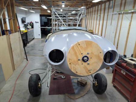
The amount of calendar time that passed during this whole process was greater than I originally thought it would be so I already had my LSA kit for 11 months by the time my engine ran. Of course this meant that when I returned home from Florida, I couldn’t resist installing the engine on the front of the airplane even though there is still a lot of other work to do on the fuselage. I got ahead of myself and installed the nose bowl to the prop flange, but now I need to go back and install the boot cowl before I can complete the cowling. The typical engine cowling used with the Corvair engine is very similar to the standard Bearhawk cowling. William Wynne sells a fiberglass nose bowl sized for the Corvair engine and then a sheet metal cowling is fabricated to go between the nose bowl and firewall with doors that open for easy pre-flight inspection.
Besides providing parts for converting Corvair engines, William Wynne provides education about the engine. Not just how to build the engine, but also how to own, operate and maintain the engine. I referred to a conversion manual that William sells, but there is also a Maintenance, Operations and Procedures manual that helps you through the flight test period and developing a POH for your aircraft. The support that William provides and the Corvair community that exists are a big part of why I decided to use a Corvair flight engine. I think there are some similarities between the Corvair community and the Bearhawk community in that I believe both draw more of the old school type homebuilders than you find in some of the other homebuilder circles.
For those of you who are interested in more details about the Corvair flight engine in general, I’ve listed some information below that largely comes from William Wynne’s website, Flycorvair.net.
More about the Corvair:
The Corvair is a General Motors designed engine, manufactured by Chevrolet. 1.8 million engines were built in the Tonawanda, NY engine plant between 1960 and 1969. The Corvair has been flying on experimental aircraft since 1960, and William Wynne has been working with them as flight engines since 1989.
Configuration: The engine is a horizontally opposed, air-cooled, six cylinder configuration. William only promotes its use as a simple, direct drive power plant. The engine configuration is very similar to Lycomings and Continentals.
Displacement: The engine is effective without a gearbox or belt drive because it has a comparatively large displacement. William supports versions that are 2700, 2850, 3000 and 3300cc. The smallest of these is twice as big as a Rotax 912. The 2850cc is very popular because it sits in a sweet spot for performance and value.
Power: The power ratings for these four displacements of Corvair flight engines are 100hp, 112hp, 116hp and 125+hp at 3000 rpm.
Weight: The 2700cc engine weighs 225 lbs ready to run.
This is effectively the same as a Continental O-200. It’s installed weight is 35 lbs more than a 912 Rotax, 25 lbs more than a Jabiru 3300 and 40 lbs lighter than a Lycoming O-235. 2850cc and larger Corvairs are slightly lighter than 225 lbs because the cylinders weigh about 5
lbs less. 3300cc Corvairs also use a billet crank which saves another 4 lbs. Aluminum pushrod tubes can be used on any of the engines to save another 1 lb.
Reliability: From the factory, the Corvair made up to 180 hp in the car and turned more than 5500 rpm. The flight engine is reliable and long-lasting because it is only operating at 55% to 70% of these levels. Conversion engines that run at the car’s red line rpm historically have short lives and cooling issues.
Cooling: The Corvair has a factory cylinder head temp limit of 575F. This is the highest limit on any mass-produced air-cooled engine ever built. The engine is also the first mass-produced turbocharged car. GM engineered the engine to have excellent heat tolerance and heat dissipation. In aircraft the engine typically runs at 325 to 350 CHT.
Parts availability: Every wearing part in the engine has continuously been in production for 5 decades. A high end Corvair conversion only has an original pair of cases, and oil housing and cylinder head castings. All other parts in the engine, including the crankshaft, are brand new. Many of the parts in the engine, like the lifters and valve train, are common to Chevy V-8s. There is no part availability issue.
Ignition: The fleet of flying Corvairs is about 500 aircraft. More than 90% of them have a dual ignition system built by William Wynne. His system uses two mostly redundant systems, one points based, the other a digital electronic system. The design has two of every part potentially subject to failure, but it utilizes one plug per cylinder. Six cylinder engines can fly on one cold cylinder, most four cylinder engines cannot. Plug fouling is unknown in Corvairs because the ignition system is 40,000 volts and uses a plug gap twice as wide as a magneto system.
Fuel: The Corvair can use either 100LL or automotive fuel. It is not bothered by ethanol in the fuel. When Corvairs were designed, car gas was a lot like 100LL; for the last 35 years every mile driven by Corvair cars was done on unleaded car gas. Many engines like 912s and modern car engines do not have exhaust valves that can withstand the corrosive nature of 100LL. William uses stainless and Inconel valves in Corvair flight engines.
Maintenance: The Corvair is low maintenance. The heads never need re-torquing. The valves have hydraulic lifters and never need to be reset or adjusted. William dislikes the term “maintenance free” because it implies a “no user serviceable parts inside” disposable appliance mentality. The Corvair is a solid, robust machine which holds its adjustments, but his program is aimed at teaching builders to be self-reliant owners.
My donor car:

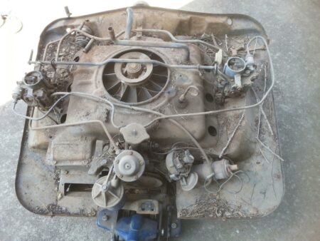
Engine removed from car
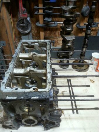
Engine after disassembly
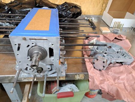
Bottom end as it returned from SPA
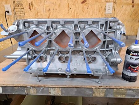
Bottom end after adding rear oil case, masking and painting
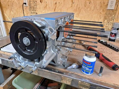
Masking removed and harmonic balancer added to rear of engine
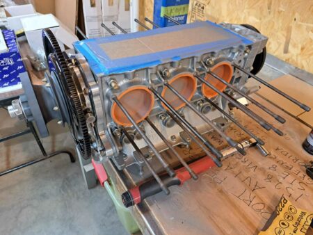
Prop hub and ring gear added to the front of engine
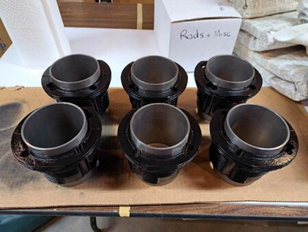
New cylinders painted
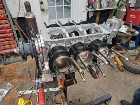
Now at William Wynne’s shop in FL. Rods, pistons and cylinders installed.
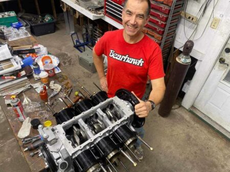
Showing off my Bearhawk gear
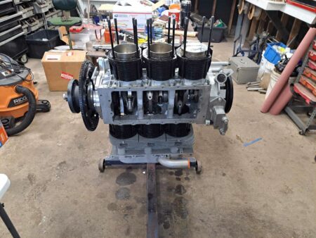
Engine is repositioned to install the head from the top and then rotated to install the second head from the top as well.
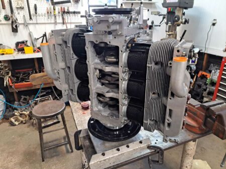
Second head now installed and engine moved to the vertical stand
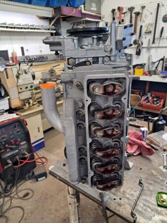
Valvetrain now installed
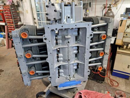
Ready to install oil pickup screen and oil pan
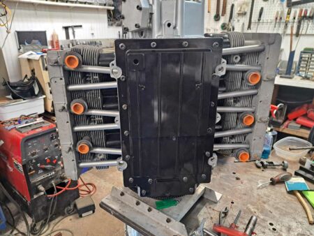
Oil pan now installed
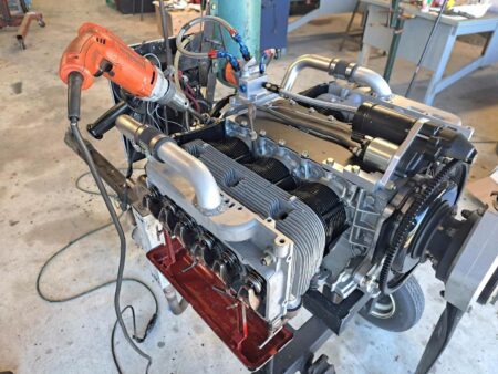
Engine has moved to the test stand. Top cover, starter and oil filter housing now installed. Drip trays mounted on heads to catch oil during pre-oiling process performed with drill motor spinning the oil pump.
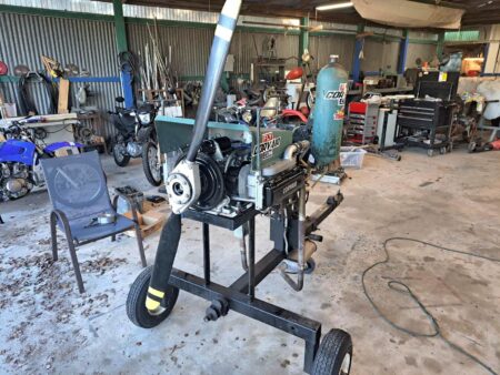
Pre-oil is complete, valve covers installed, and cooling shroud added in preparation for test run.
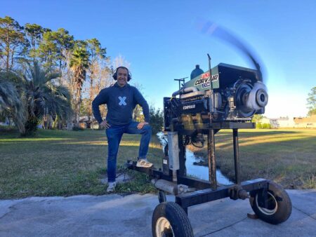
And it runs!
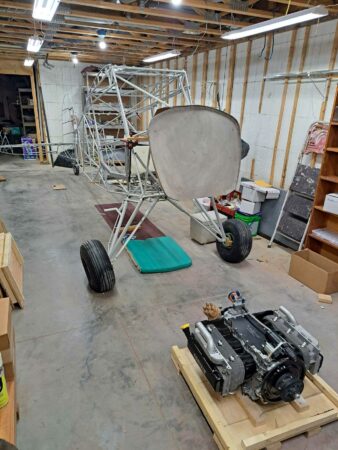
Back in Kansas, engine is waiting to be mounted on my LSA.
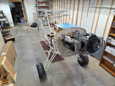
Engine mounted with William Wynne’s engine mount. The Corvair uses a bed mount.
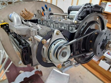
20A alternator now installed.
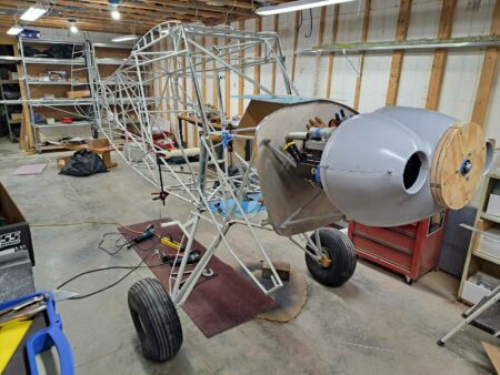
Nose bowl installed. This nose bowl is designed to use the 13″ spinner from Van’s Aircraft.
Cowl Modifications for Extreme CHT Cooling
Source: 2023 Q4 Beartracks
Scott Williamson lives in the Phoenix area with his Bearhawk 4-Place. He struggled to keep the engine cool, with high ambient temperatures and high horsepower not making things easier. In the end he fabricated a fiberglass cowl exit that made a big difference in temperatures. He also enlarged the inlets and moved them up and outboard a little. The mold for the new inlets was a dog dish. Thankfully most folks won’t need to pursue such measures, but these changes fixed the high CHTs for Scott.


Bearhawk Five Flight Testing – Tyler Williams
Source: 2023Q4 Beartracks, Tyler Williams
Some people actually know what they are doing. Me? I’m a novice. Prior to this project I had never built, rebuilt, or performed any significant repair to an airplane. Yet, here I am, 2 ½ years after receiving my Bearhawk Five kit, with a finished airplane.
Now, with my newly gained builder experience and a paltry 250 hours under my belt as a private pilot, I become a test pilot.
It has been 10 minutes since the FAA inspector shuffled his pile of papers into a folder, stepped into his car and drove away. Freedom. I preflighted N521TY twice the day before and then again with the inspector today. She was fueled up and ready.

I’m in the cockpit now, staring down runway 04. The big Lycoming O-540 is growling happily, ready and waiting for me to push that throttle full forward and give it the first taste of freedom. I go over a plan again in my head, “Accelerate. Verify airspeed alive. After the heels break ground, level off 5 ft above the runway and quickly confirm correct control authority, pull and maintain a shallow climb out to keep things cool. Watch temps. Keep climbing if all is well. Level off at 5,500 ft. FLY. Enjoy. Simulate an approach and bring the airspeed back to the onset of stall buffet and recover. Record speed and jot down an appropriate first final approach speed from there. Return to the field and set up an approach. Execute a three point landing with no flaps. Have a beer and celebrate.”
Ok, I exhale, push the throttle forward and my back gets pinned to the seat. The acceleration feels like I have let an animal off its leash. The tail is up. Wow! The handling is easy on the ground. By the time I reach full throttle she is light and ready to fly. She’s
up! I rock the wings and wag my tail, and then start climbing. 100 ft…200 ft…400 ft…600 ft…then WTF!?
My back comes off the seat under deceleration as I hear the sickening sound of an engine losing power. I drop the nose instinctively and glance at the airspeed. 75 kts. Ok, keep pressure on the nose. The throttle is still to the firewall. RPM stable but lower. Not climbing much now, but I haven’t lost all power, just some…a LOT. S*#@T, come on, really?! I glance at the adjacent runway as a bailout option and make a left turn towards it. It would be a super steep approach with a hard slip to stick in on the pavement from mid-field at this altitude. I could maybe do it, but I have consistent power and level flight now with no hiccups, just not full power. I do a quick instrument scan. Everything is in the green. Ok, left turn to downwind for runway 04. Maintaining 600ft. I try for a quick diagnosis as I fly the downwind. I leave the throttle firewalled, since it hasn’t moved and I don’t want to know what it may do if I move it. The prop responds normally but doesn’t help. I make a small mixture adjustment. Still no change. Then I hear the RPM waiver up and down briefly and then back to the same power. Is it the governor? Hell, I don’t know I need to land this plane and find out on the ground! Instrument scan…everything is still in the green. Now, how about that approach speed? So much for a simulated approach to figure out how she behaves. Oh well. I know how to land an airplane. We flew some 60 kts, no flap approaches during my Bearhawk transition training, so that should be good. Ok, 60 kts and no flaps because I haven’t tested those yet. I pull power, roll trim for 60 and notice how similar the control and trim response are to the 4-place I flew. In fact it all feels familiar to my hands, which is comforting at this moment. The landing approach is very brief since I’m only at 600ft, but in that time of intense focus I still manage to feel joy and pride when I notice how well the airplane is handling on glide. It was just as I imagined it would be, like a dream. I feel no friction in the controls, just fingertip pressure with immediate and predictable response from the plane. I’m over the threshold now, entering ground effect and rounding out. I think to myself, “Wow, she sure is docile.”

Float, flare, and grrrrrrease. First I smile and think to myself, “What an amazing airplane.” Then as I slow to taxi speed, I instinctively push the carb heat knob back in, and all those joyful thoughts are quickly replaced by the original “WTF?!” Nothing seems out of place. The engine is happy now and the instruments are happy. Maybe it was fuel flow, maybe something else. I taxi over to my hangar and do a runup to test everything again. She throttles up just fine and sounds great. I do a mag check, cycle the prop, test the mixture response, check the carb heat function, and then a full power static RPM check.
Everything seems ok. I disconnect the fuel line at the carb and do a quick fuel flow test. Everything checks out. I still have no idea what happened. But then again, I’m a beginner at ALL of this. Time to make phone calls. First, I glance around the panel and sit for a moment to think. Briefly, I have the thought, “I don’t remember pulling carb heat for my approach, but I remember pushing it back in while taxiing.” Weird. Must have done it without thinking. It definitely was pushed in for takeoff as I remember checking that as part of my runup checklist. Besides, the power loss was sudden and didn’t happen until I was at 600 ft. So, that couldn’t be it.”
The phone calls to various experts sparked a series of ideas and things to adjust that could diagnose/fix my sudden power loss/RPM drop issue. None of these uncovered the issue. I check adjustments, follow all recommendations and do another full power runup, as advised. All I can do so far is trust the people that actually know what they are talking about. As I reach full throttle I notice the carb heat knob creep out maybe ½”. Now THAT catches my eye! Suddenly things start to make sense and I start to get happier as I realize my engine is fine after all. Something is amiss with my carb heat box. Could it be opening itself when hit with enough air pressure? It is a brand new design after all and I’m the first one to fly with it. Time for another test flight. And this is what phase 1 is all about.
I crawl back in the cockpit, fire up the beast and make a new plan to depart the crosswind runway. In the event I need to abort on climb out, I can turn and land into the wind on the adjacent runway. I line up and firewall the throttle. I see 2700 RPM and she’s off! Climbing out, I glance at the airspeed and as I pass through 80 kts, the carb heat knob shoots out and the engine chokes again. AH HA! I push it back in and full power returns. I have an answer…well half of it anyway! Man that feels good. After a spin around the pattern I come back to land. The carb heat is being blown open after about 80 kts. It’s a strange design issue, but it should be an easy fix. Replacing the standard push/pull cable with a detented one will keep it locked in any position. But why such a drastic change in RPM? Seems like it was really choking the engine rather than causing a small RMP drop. It turns out the carb heat shroud that I installed was not allowing adequate airflow. It wrapped too far around the exhaust and needed further trimming. The education continues.
The following weekend, I fuel her up and set off into the sky to test the new cable and modified shroud. This time on climb out, the carb heat stays put and the engine runs beautifully. I continue my climb to gain some decent altitude and think about the initial series of flight maneuvers I finally get to do. Then I glance down at my engine monitor. My oil temp is at red-line and climbing! Come-on, now what?! I abort the flying tasks yet again and quickly return for a landing. Back on the ground, I pull the cowling off, check the baffling, check the oil cooler, disconnect the oil cooler lines and ensure oil is actually flowing and on and on. Everything seems good. Time for phone calls again. After a series of ideas that were all checked off, I hear, “It could be a bad Vernatherm.” I say, “Oh the Vernatherm. Yeah I’ll check that.” I did not say to my friend what I was really thinking…”What the heck is a Vernatherm?” The education continues. I learn what it is, how it works, and how to remove and inspect it for correct function. Sure enough…bad vernatherm. I install a new one and wait for the weekend to arrive with great anticipation.

What will the engine monitor say this time? Will I get to fly for more than 5 minutes before I’m forced to land and troubleshoot something else? Will I get to enjoy a nice flight? Maybe I’ll get some altitude for the first time and do some maneuvers? And I did.. Finally, I flew my new Bearhawk Five and landed when I wanted to. The carb heat stayed put and didn’t choke the engine when applied, the oil temps were perfect. The engine was truly happy, and so was I. Since the first couple weeks of troubleshooting I have been enjoying a wonderful airplane. I continue to learn and refine things each time I fly. This 40 hour test period is a valuable time. I’ve sorted out a heavy wing and have her flying hands off at cruise now. I’ve fiddled with the gas caps and finally dialed in how to use them with little to no cussing. I tightened up the trim tabs as others have done, to remove the play and vibration in them. I added some turbulator strips to the horizontal stabilizer struts. She feels super smooth now. The airplane continues to get better, and more refined with each test and tweak, and so does my technique, knowledge and experience. The flight testing is fun. Maneuvers are fun. Stalls of every kind are very fun…way better than circling the field for hours and “flying off the time.” I’m working on my short field techniques, learning what the airplane likes and figuring out how to get the most out of it. To say I’m enjoying it is an understatement. Being a pilot again feels amazing. The 2.5 years spent building now seems like the blink of an eye. I’m back in the cockpit now, doing what I love.
The numbers I have at this point are not really news-worthy. It performs as advertised for an unmodified, kit-built Bearhawk Five and I couldn’t be happier about this. The takeaway for me so far is that the learning thankfully never stops. The test period has not been mindless circling to burn off time. It has been an education. I have more textbook testing procedures to perform during this phase 1, and then lots to work on after that. To really take this plane where it was intended to go, I’ll be testing and learning far beyond the 40 hours around my airport. This is not a $100 hamburger machine after all. It is a tool for exploration. For now, I’m still a novice, but each new step out of my comfort zone and each step closer to the edge of the envelope adds to the bucket of knowledge, experience and stories to tell. And that is what it’s all about.

Engine Cooling Follow-Up
In the last issue I wrote about cooling, especially based on the shape of the lower cowl. I decided to install a fixed lip at the cowl outlet, and in the process also enlarge the opening by an inch and a half. I had not wanted to make the opening any larger over concerns about how thin the connection area was between the two lower cowl halves, but the new lip served as a doubler so I enlarged the opening. Here are the before and after:


I had hoped to download the EMS recorded data so that I could be more quantitative, but unfortunately it was lost in the fire. Generally, I can say it was a vast improvement. Before, a takeoff with a warm engine would have the CHTs over 400 in the first 1500-2000 feet, climbing at 90 knots. With the new cowl lip, Mike and I were able to climb with our Oshkosh load at 70 knots and the temps started to reach 400 climbing through 6000 feet. At a less steep and more normal climb angle, temps were never a concern, which was the intended design goal. While at Oskhosh, I took photos of several other airplanes for comparison. There is a lot of variety. Bobby Stokes enlarged the intake openings, added the Carbon Cub style louvers, and lower cowl flaps (O-540):


Mark Scott uses more typical louvers with his O-540:


Bill Anton had the largest lower cowl opening of the Oshkosh samples, though I believe he also has the most horsepower and thus BTUs to shed. I also appreciate how he riveted the lip on the top (behind the yellow) of the lower cowl.

The installation is visually appealing. None of this analysis is conclusive enough to say “do it this way,” but hopefully seeing some of the variety will help narrow down the norms of lower cowl configurations.
Russ Erb’s Engine Cooling Experience
Source: 2021 Q2 Beartracks, Russ Erb
Three Sigma was originally built with a cowl flap that had sufficient exit area according to experience and rules of thumb. However, engine cooling was marginal and power settings were limited to about 65% power continuous. While the cowl flap exit area was sufficiently large, the airflow areas through the cowl were suspected to be significantly less, being blocked by the exhaust pipes, mufflers, heat muffs, and a large amount of SCAT tubing. The cooling air, having flown over the cylinders, was having a hard time getting to the cowl flap exit. Because cooling was so marginal, the cowl flap was always in the full open position.
The easy way to open up more cooling exit area was to cut holes in the sides of the cowling such that the cooling air could flow around the cylinders and out the side of the cowling without having to pass around the exhaust pipes and SCAT tubing. The first modification was to add louvers from Avery Tools (no longer in business). This showed some improvement, but not as much as desired. A more aggressive set of louvers were built up from sheet aluminum to fit in the same mounting. It was hoped that the more aggressive louvers would produce a low pressure area to help draw the cooling air out.
Cooling was better with these new louvers, but the cowl flaps remained fully open unless the outside air temperature was very cold, such as about 40F or below.
My cooling problems may be somewhat unique to Three Sigma. At Oshkosh 2013 I spoke to another Bearhawk builder who also had a Lycoming O-540. Looking up his cooling exit showed a similar sea of SCAT tubing like on Three Sigma. However, he reported having no troubles with engine cooling. There was one difference in the cowling, though. Three Sigma was built with the MC-3B Pitts nose bowl called out in the plans and Beartracks. The other Bearhawk was built with the nose bowl provided by R&B Aircraft. The R&B Aircraft nose bowl lower edge is about one to two inches lower than the MC-3B nose bowl, which means the lower skin of the cowling is that much lower below the exhaust pipes, which means that the area for airflow in this area is doubled, allowing for better cooling.
An unexpected result happened after the 2018 condition inspection. A portion of the lower cowl behind the carburetor was found to have cracked and fully separated. The cowl was repaired with a doubler that reduced the open area around the carburetor, which was assumed to be an auxiliary cooling air exit path. However, for reasons not fully understood, this change resulted in noticeably better engine cooling. Why this happened I can’t explain.
With this change, the cowl flap can be closed after a few minutes at cruise power for outside air temperatures below 60F and maybe even 70F. While closing the cowl flaps theoretically reduces drag and increases cruise airspeed, in practice the difference is unmeasurable. However, it does keep the engine from over-cooling itself.

Engine Cooling – Lips, Louvers and Flaps
Source: 2021 Q2 Beartracks, Jared Yates
Engine cooling is on the short list of things that builders have ongoing problems with. It doesn’t have to be this way, but I’m not really one to talk. Last week on a hot summer afternoon, we flew our Bearhawk 20 miles north for a photo mission and ice cream run. We shut down long enough to eat ice cream and visit for a few minutes, then started up to fly home. This is the worst case scenario for cooling, since the cowl temperatures rise after shutdown. While enroute, the engine is making lots of heat, but there is airflow to remove that heat. Once the plane is not in the realm of flying speed, the residual heat in the engine parts gets transferred to the air inside the cowl, and everything except the engine gets warmer. After departure and reaching 2000’ AGL, our highest CHTs were up to 425 and climbing.
The challenge with this scenario is that reducing engine output is one way to reduce the temps, but that also reduces the airspeed, which reduces the cooling airflow. I know from experience and education that cooling improvements are incremental. One silver bullet seldom solves the problem, but if I’m going to fly to Oshkosh this year, I need to start incrementing.
Cooling effectiveness feels like black magic, but as I wrote about in the 2015 Q3 issue of Beartracks, it is fairly easy to measure and quantify with a home-made manometer, followed by noting CHTs in flight after making a change. If one wants to burn the fuel and go to the trouble, it is possible to set up the manometer, fly to get a baseline, make a mitigating modification that is supposed to help lower temps, and then fly to see if the pressure differential changed.
As I prepare to start this process, I’ve been collecting data about what those mitigations are. First, we have to ensure a good seal between the baffles and the top cowl, or do like Rob Caldwell did and install a plenum:

One way to study this seal is to watch the wear pattern where the rubber strips rub the aluminum. Another is to use a flashlight to check for leak areas. I feel like in my case I have this worked out pretty well, so on to the next step.
Perhaps the two biggest variables are the inlet and outlet areas. The inlet areas are fairly fixed unless we start designing our own nose bowl openings, but we see lots of variation in the outlet size. This photo shows Ray Strickland’s O-540 powered Bearhawk:

He has a large area, along with a pronounced lip to help reduce pressure. In my case, I’m not running such a large opening, though I feel like the maximum size of the opening has been limited by the way I’ve tied in the fiberglass airbox fairing. If I move the trailing edge of the cowl forward, it will diminish the amount of aluminum left to hold the lower cowl together, but maybe this is what I’ll need to do.
That brings us to the next mitigator, which is the lip. The lip is most commonly composite or aluminum. Starting with a soft 5052 or similar aluminum, the lip can be made with a shrinker and stretcher. That type of lip will also add strength to the lower cowl, just as flanging a rib adds stiffness. It has been proposed that the upward flex of an un-lipped cowl in this area might actually lead to an automatically-reduced opening size, which would be most unfortunate. What is the optimum length of the lip and angle? I can’t tell you, but it sure would be interesting to have some data. For now the best I can do is study the sample of available planes, and hope that the Type-Certificated crowd is flying behind an R&D department that considered all of the possibilities. Intuition and observation seem to point to around 2 inches of material at an angle of around 30 degrees.
All of the above mysteries about cowl lips are moot with the next option, which are adjustable cowl flaps. In some ways, we could think of the lip itself as a cowl flap, but that it’s always open. When enabling the option to adjust the opening, the design considerations change. Builders have executed a variety of different designs. Jonathan Battson made two openings, roughly 5×8 inches, but says he’d rather have them 30% bigger:

He used a piano hinge at the leading edge and made the flaps out of .025 aluminum. When open, they are deflected around 4 inches at the trailing edge. Jonathan uses an adjustment knob to manually operate the flaps and finds that he can reduce CHTs by 30 degrees, though he finds that he usually sets them either fully open or fully closed. One of his primary concerns was being able to keep the engine warmer during long descents. And since engine cooling makes drag, it makes sense to only produce the cooling and drag when the engine needs it. This is a big advantage of adjustable cowl flaps. Here’s a video of Battson’s cowl flaps.
Jon Wheeler used a similar concept, but used input from Jonathan to increase the size to 8.25 inches long, 6.5 inches wide, and 4.5 inches of deflection. Jon used electric linear actuators (Actuonix P16-100-64-12-S) instead of a manual cable. Jon also moved the flaps further up on the cowl, closer to the area where builders have also used louvers.


Speaking of louvers, those are a common option, especially on airplanes with the bigger engines. Lots of folks use salvage Piper parts (PN# 87405-802 (left), PN#87405-803 (right)) with the intent being to further reduce the air pressure below the engine. Jon Wheeler’s implementation of cowl flaps certainly approaches the function of the louvers and how they exploit the relative low pressure area there. Builder Bobby Stokes was having trouble with cooling, so he did some tuft testing and manometer testing. In his louver installation, the cooling and differential pressure were both worse. His louvers are much higher up on the cowl than many others, and there has been some discussion on the forum about which direction the louvers should face. Bobby did find that the fixed cowl flap or deflector at the bottom made the largest difference. He made a version that was adjustable, but didn’t find that the adjustment was necessary and has since gone back to a fixed flap.

Another common mitigation is to round the angle that the exiting airflow experiences at the corner between the firewall and the tunnel. I added a fairing here a few years ago, made from .020 2024-T3, bent on a slip roller. The idea is that this radius fairing helps reduce airflow separation right at the point that shows up in silver on the picture of Ray’s airplane above.
Next quarter I’ll have more news, either a tale of what didn’t work, or more hopefully, what did.
The Incremental Improvement of Engine Temperatures
Source: 2020 Q4 Beartracks, Karl Clifford
My son, Jeffrey, purchased a four-place Bearhawk Quick Build Kit #82 in 2009. The Kit had originally been purchased in 2007 from AviPro Aircraft, (now Bearhawk Aircraft) by someone else, who had not even uncrated the kit. I have been Jeff’s helper in building the plane over the last ten years. The airworthiness certificate was finally issued on July 2, 2020. N976JC flies great. The engine is a new Lycoming YO-540-A4D5 rated at 250HP. Propeller is a constant speed two-bladed Hartzell carbon fiber. It has a Vetterman exhaust, a JPI EDM-900 engine monitor, and a Garmin G-5 electronic flight instrument. Empty weight came in at 1480 pounds. Very simple.
The only meaningful changes from the original design are a large skylight, a 2 inch extension of the fiberglass nose bowl to accommodate the very long neck on the Hartzell prop hub, and rigging the flaps so they can go negative about 4 degrees to achieve a slightly faster cruise speed.


We have flown it about 50 hours. The performance is unbelievable. While we have not fully mastered its STOL capabilities, we have gotten takeoffs and landings down to around 300 feet, with room for improvement I believe.
Jeff and I are both fairly tall guys, and with the seat all the way back we could not reach the flap handle without loosening our shoulder harness and leaning way forward and down. Not something we wanted to be doing when flying low and slow. So we made a short T-shaped grab handle that swings back from the flap handle that allows us to easily get the first notch of flaps without leaning way down. We can then easily reach the flap handle itself for subsequent notches. We also modified all flap notches so that the top button does not have to be pushed to pull flaps. The top button is pushed only to lower flaps. We like both of these changes.
The only real “problem” we encountered was high CHTs. We went thought a number of changes to the baffling before we finally arrived at what seems to work best. I would like to briefly describe what we ended up with so that subsequent builders might benefit from our experience. I suspect a fair portion of our problem was due to trying to break-in a new engine in the hot summer temperatures of West Texas. While we were flying mostly in the early morning hours, the OATs were still in the 80s and low 90s mostly.
During the engine installation we had very carefully installed the Van’s baffling kit for the 0-540 per Van’s instructions. It is a quality kit, well worth the money. We had very tight baffling.
Initially the CHT on takeoff for #2 cylinder (left front) and #5 (right rear) would go way over 400º F on takeoff with only a very short climb out. The CHTs on the other cylinders were also high, but not like #2 and #5. We would be pulling back the throttle to about 50% power very soon after takeoff to keep CHTs down. Of course, the Bearhawk still climbs out nicely even at only 50% power. We understand that the very rich fuel flow with full throttle helps cool the cylinders, hence the reason for normally taking off and climbing out with full throttle. But that was just not working for us.
The first thing we did was to increase the size of the opening at the bottom rear of the engine cowling to hopefully increase airflow over the engine. That helped a lot. Mark Goldberg had told me back during the building process to make that opening “plenty big”. Wish I had really taken that to heart. Make it PLENTY BIG. But that was not enough to totally solve the problem.

The next thing we did was to round out the bottom edge of the firewall with a rolled piece of aluminum sheet. The photo to the left shows the enlarged opening and the rolled sheet exit. I had read that the Van’s RV builders do this a lot. I was surprised how much this helped. Funny how moving air does not like sharp corners. But that was still not enough to solve the problem. I would mention that I later saw a similar rounded edge on the bottom of the firewall of a recent model Husky. So I guess the experts also think this helps.
Next we fabricated and added little inter-cylinder baffles on both sides of the barrels of the middle cylinders. These inter-cylinder baffles did not come with the Van’s baffle kit. A lot of air flow was being lost through these openings between the cylinders. Closing these openings helped. At this point the CHTs on all cylinders except for #2 and #5 were down in an acceptable range.
Next we looked at the #2 cylinder (left front) more closely, We theorized that the upward moving prop on the left side was pushing air up and back over the top of the #2 cylinder, mostly missing it. There is a lot of extra room inside the cowling above the #2 cylinder. Using aluminum sheet we added a simple “ceiling” in the tunnel running from the opening in the nose bowl back to just above the #2 cylinder. The ceiling begins just above the top of the opening in the nose bowl and extends straight back with a downward lip at its rear to force air down toward the #2 cylinder. This largely solved the CHT problem for the #2 cylinder. Our theory that the CHT problem with the #2 cylinder was being caused by the upward moving prop pushing air up and back over the top of the #2 cylinder seems to have been correct. That theory seems to be further supported by the fact there was not a similar problem with the #1 cylinder (right front). The downward moving prop on the right side pushes the air down and back directly into the #1 cylinder, not over it. So the right side seems to function fine without a ceiling in the tunnel. I would mention that a part of the problem with the high CHT on #2 cylinder is that it has the hottest EGT at all throttle and rpm settings. Nothing we can do about that. We did check for an intake manifold air leak, with none found. This hottest EGT is just due to the way the air/fuel mixture is distributed in the intake manifold among the cylinders. It does make the need for adequate air cooling for the #2 cylinder that much more important.

Next we looked more closely at the #5 cylinder (right rear). The location on the engine case of the #5 cylinder is staggered forward somewhat and the rear baffle behind it is set back several inches from the cylinder so as to be in line with the rear baffle for the left side of the engine. We theorized that the air was to some extent flowing over the top of the #5 cylinder and missing it, and that something was needed to force all the air down toward the cylinder. So we added a new “false” rear baffle located just behind the #5 cylinder that curves upward and forward to catch and force all the air down toward the cylinder. That new false rear baffle extends up all the way to the top of the engine cowling and has a gap seal at its top. We did leave a fairly small opening at the far right side of the false baffle to allow some air to flow on back to the 4” scat tube opening in the right rear baffle that leads to the oil cooler located behind the right rear baffle. This false rear baffle solved the CHT problem for the #5 cylinder. We had some initial concerns that it might create problems for the oil cooler. But we’ve noticed no increase in oil temps. The oil cooler continues to work great, with oil temps rarely going over 200º F.

We managed to get all of these changes made before OATs cooled off too much in the fall. With 90º F OAT we can now takeoff and climb out without any CHT going over 380º F if we don’t extend the climb out too long. Even with a more extended climb out all CHTs stay well under 400º F. At cruise all CHTs are down below 375º F and the spread among all cylinders is only about 20º F. On a cooler day CHTs are much lower. In cruise we can now lean the hottest EGT to over 1300º F. Before these changes we could not lean at all. Some of the improvement is undoubtedly due to the break-in of the new engine, so we cannot give total credit to the baffling additions.
It would have been much easier, and made for a much cleaner installation, if we had made these baffling additions during the original construction process, rather than adding them piecemeal as we ended up doing. So, I’d recommend to anyone currently building that he or she consider incorporating these additions to the baffling initially. Feel free to contact me if you have any questions or comments. Karl Clifford, Lubbock, Texas.
806-470-1480 4636c@att.net


