


Source: 2024 Q1 Beartracks, David Swartzendruber
I am building a Bearhawk LSA and one of the engine options for the LSA is a Corvair auto engine conversion. This is what I have chosen for my LSA and I completed my engine build at the end of 2023 during a 3-day supervised build in William Wynne’s shop in Florida. Bob Barrows and William Wynne worked together to design a motor mount for the Corvair engine in the Bearhawk LSA and this mount is available from William. But I’ll back up and start at the beginning of my story.
Like many of you, I decided I wanted to build an airplane many years ago, about 33 years ago for me. However, along the way I lost that dream when it didn’t seem like time or money would allow that to happen. About five years ago, that dream was rekindled when I picked up an unfinished non-Bearhawk project for a very affordable price that was designed to use a VW engine conversion. As I thought about what to do for an engine, I came across the Corvair and William Wynne’s website, Flycorvair.net, and began to consider using a Corvair engine in that project. Through the information on Flycorvair.net, I also discovered the Bearhawk LSA was a good candidate for the Corvair engine and I became less enthusiastic about the project I had acquired. I eventually decided to order a Bearhawk LSA kit and sell the other project.
Having already started down the path of building a Corvair flight engine, I thought I would go ahead and complete that while I waited for my LSA kit to arrive. The first step is to get a conversion manual from William Wynne. This manual includes information about which core engines can be used to build a flight engine. I picked up a 1965 Corvair parts car for $250 and the engine from that car became my core. Corvair flight engines always start with a 1964-1969 engine because engines earlier than that had a smaller stroke, lower displacement and lower strength crank and rods. My core engine was locked up, but I was still able to disassemble it and discovered that the piston rings on one piston had rusted to the cylinder wall. To my surprise, I found that my 1965 engine had a crankshaft and rods from a 1963 or earlier engine. This ended up not making any difference because I decided to go all out and build the bored and stroked version that bumps the displacement up from 164ci to 200ci, also referred to as the 3.3L. The 3.3L engine requires a new billet crank, billet rods, forged pistons and special cylinders so my old crank and rods weren’t needed anyway.
I shipped my engine case and heads off to Sport Performance Aviation (SPA) in Florida for machine work on the case and heads and complete rebuild of the heads. Larger holes are bored into the case to accommodate larger cylinders and some clearance machining is done inside to allow the rods on the stroked crank to clear the case. SPA developed the 3.3L stroker parts, so I bought the new crank, rods, pistons, rings and cylinders from SPA. In addition, SPA has developed a 5th bearing system for the front of the crankshaft to react the propellor loads not normal to an automotive application. All the other standard conversion parts from William Wynne are also used in the 3.3L stroker, so I ordered those from William, including:
-Prop hub, safety shaft and hybrid mounting studs
-Ring gear, starter and aluminum top cover
-Billet aluminum oil pan with oil pickup tube and screen
-Oil filter housing, oil cooler adapter and AERO-Classics oil cooler
-Rebuilt oil case with high volume oil pump
-Rebuilt distributor with Willam’s dual ignition conversion
-Reground camshaft developed by Crane cams for William Wynne
-Alternator mounting bracket
-Modified valve covers to add oil fill tube and vent ports
-Billet aluminum pushrod tubes
-Rotec throttle body injector
-Stainless steel intake and exhaust manifolds
-Engine mount for Bearhawk LSA
-Fiberglass nose bowl
-Engine baffles are coming later but are also offered by William
Once I had all the parts, I began to assemble the engine. The case came back from SPA already closed with the crankshaft, camshaft and 5th bearing installed. This would normally be done at home on the lower displacement engines, but on the stroker motor SPA wants to make sure everything goes together with adequate clearance and rotates freely. I installed the hybrid studs, safety shaft, prop hub and ring gear on the front of the crankshaft and then added the oil case to the rear of the engine.
At this point, I masked things off and painted the engine case and rear oil case. I also cleaned up the new cylinders and painted them. More assembly would have followed from here, but I had decided to take advantage of the supervised engine build opportunity that William Wynne offers. I traveled to Florida with my partially assembled engine and all the other parts and over the course of three days, completed the engine build and test ran it on Williams test stand with a club prop. I liked the idea of spending 3 dedicated days and completing the engine and I also valued the opportunity to run the engine on the test stand and learn from William while I was there.
The amount of calendar time that passed during this whole process was greater than I originally thought it would be so I already had my LSA kit for 11 months by the time my engine ran. Of course this meant that when I returned home from Florida, I couldn’t resist installing the engine on the front of the airplane even though there is still a lot of other work to do on the fuselage. I got ahead of myself and installed the nose bowl to the prop flange, but now I need to go back and install the boot cowl before I can complete the cowling. The typical engine cowling used with the Corvair engine is very similar to the standard Bearhawk cowling. William Wynne sells a fiberglass nose bowl sized for the Corvair engine and then a sheet metal cowling is fabricated to go between the nose bowl and firewall with doors that open for easy pre-flight inspection.
Besides providing parts for converting Corvair engines, William Wynne provides education about the engine. Not just how to build the engine, but also how to own, operate and maintain the engine. I referred to a conversion manual that William sells, but there is also a Maintenance, Operations and Procedures manual that helps you through the flight test period and developing a POH for your aircraft. The support that William provides and the Corvair community that exists are a big part of why I decided to use a Corvair flight engine. I think there are some similarities between the Corvair community and the Bearhawk community in that I believe both draw more of the old school type homebuilders than you find in some of the other homebuilder circles.
For those of you who are interested in more details about the Corvair flight engine in general, I’ve listed some information below that largely comes from William Wynne’s website, Flycorvair.net.
More about the Corvair:
The Corvair is a General Motors designed engine, manufactured by Chevrolet. 1.8 million engines were built in the Tonawanda, NY engine plant between 1960 and 1969. The Corvair has been flying on experimental aircraft since 1960, and William Wynne has been working with them as flight engines since 1989.
Configuration: The engine is a horizontally opposed, air-cooled, six cylinder configuration. William only promotes its use as a simple, direct drive power plant. The engine configuration is very similar to Lycomings and Continentals.
Displacement: The engine is effective without a gearbox or belt drive because it has a comparatively large displacement. William supports versions that are 2700, 2850, 3000 and 3300cc. The smallest of these is twice as big as a Rotax 912. The 2850cc is very popular because it sits in a sweet spot for performance and value.
Power: The power ratings for these four displacements of Corvair flight engines are 100hp, 112hp, 116hp and 125+hp at 3000 rpm.
Weight: The 2700cc engine weighs 225 lbs ready to run.
This is effectively the same as a Continental O-200. It’s installed weight is 35 lbs more than a 912 Rotax, 25 lbs more than a Jabiru 3300 and 40 lbs lighter than a Lycoming O-235. 2850cc and larger Corvairs are slightly lighter than 225 lbs because the cylinders weigh about 5
lbs less. 3300cc Corvairs also use a billet crank which saves another 4 lbs. Aluminum pushrod tubes can be used on any of the engines to save another 1 lb.
Reliability: From the factory, the Corvair made up to 180 hp in the car and turned more than 5500 rpm. The flight engine is reliable and long-lasting because it is only operating at 55% to 70% of these levels. Conversion engines that run at the car’s red line rpm historically have short lives and cooling issues.
Cooling: The Corvair has a factory cylinder head temp limit of 575F. This is the highest limit on any mass-produced air-cooled engine ever built. The engine is also the first mass-produced turbocharged car. GM engineered the engine to have excellent heat tolerance and heat dissipation. In aircraft the engine typically runs at 325 to 350 CHT.
Parts availability: Every wearing part in the engine has continuously been in production for 5 decades. A high end Corvair conversion only has an original pair of cases, and oil housing and cylinder head castings. All other parts in the engine, including the crankshaft, are brand new. Many of the parts in the engine, like the lifters and valve train, are common to Chevy V-8s. There is no part availability issue.
Ignition: The fleet of flying Corvairs is about 500 aircraft. More than 90% of them have a dual ignition system built by William Wynne. His system uses two mostly redundant systems, one points based, the other a digital electronic system. The design has two of every part potentially subject to failure, but it utilizes one plug per cylinder. Six cylinder engines can fly on one cold cylinder, most four cylinder engines cannot. Plug fouling is unknown in Corvairs because the ignition system is 40,000 volts and uses a plug gap twice as wide as a magneto system.
Fuel: The Corvair can use either 100LL or automotive fuel. It is not bothered by ethanol in the fuel. When Corvairs were designed, car gas was a lot like 100LL; for the last 35 years every mile driven by Corvair cars was done on unleaded car gas. Many engines like 912s and modern car engines do not have exhaust valves that can withstand the corrosive nature of 100LL. William uses stainless and Inconel valves in Corvair flight engines.
Maintenance: The Corvair is low maintenance. The heads never need re-torquing. The valves have hydraulic lifters and never need to be reset or adjusted. William dislikes the term “maintenance free” because it implies a “no user serviceable parts inside” disposable appliance mentality. The Corvair is a solid, robust machine which holds its adjustments, but his program is aimed at teaching builders to be self-reliant owners.
My donor car:
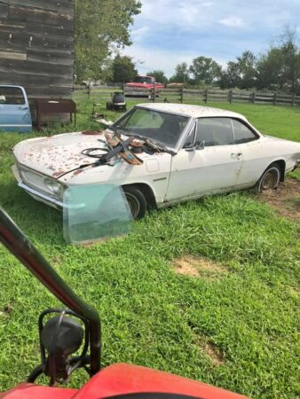
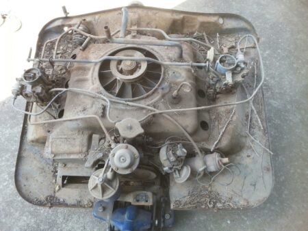
Engine removed from car
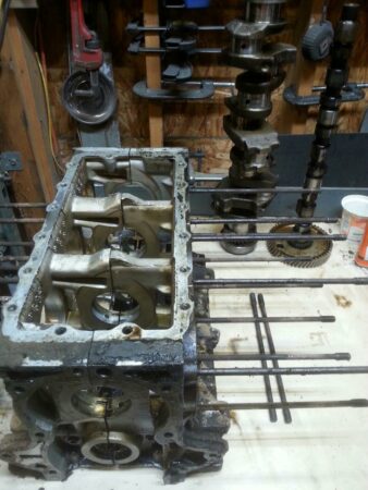
Engine after disassembly
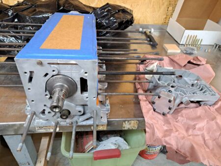
Bottom end as it returned from SPA
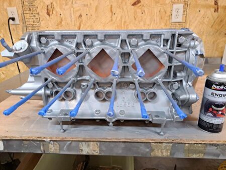
Bottom end after adding rear oil case, masking and painting
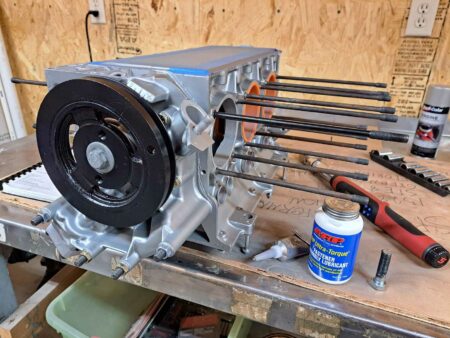
Masking removed and harmonic balancer added to rear of engine
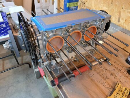
Prop hub and ring gear added to the front of engine
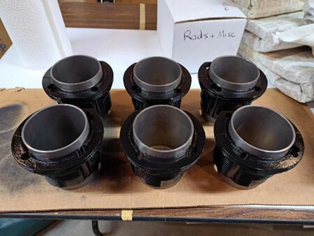
New cylinders painted
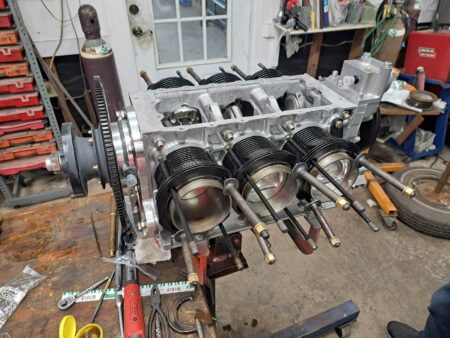
Now at William Wynne’s shop in FL. Rods, pistons and cylinders installed.
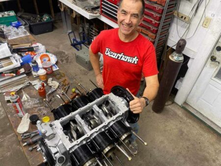
Showing off my Bearhawk gear
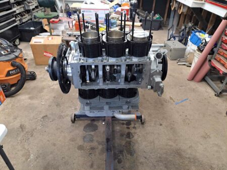
Engine is repositioned to install the head from the top and then rotated to install the second head from the top as well.
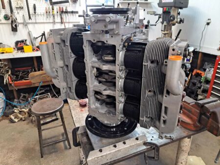
Second head now installed and engine moved to the vertical stand
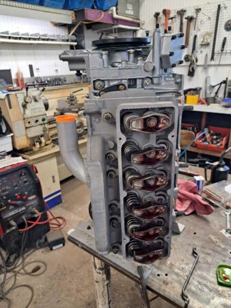
Valvetrain now installed
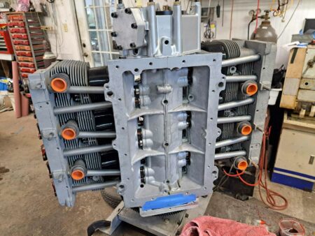
Ready to install oil pickup screen and oil pan
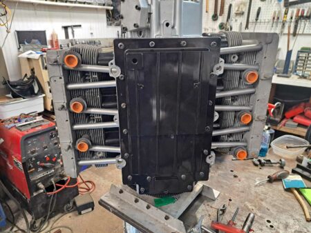
Oil pan now installed
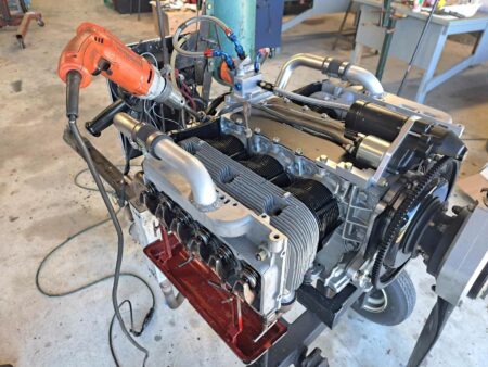
Engine has moved to the test stand. Top cover, starter and oil filter housing now installed. Drip trays mounted on heads to catch oil during pre-oiling process performed with drill motor spinning the oil pump.
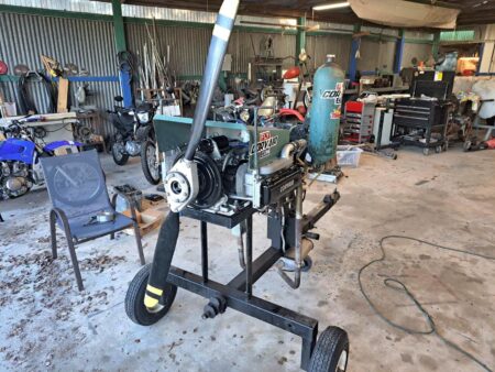
Pre-oil is complete, valve covers installed, and cooling shroud added in preparation for test run.
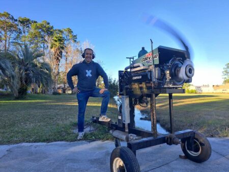
And it runs!
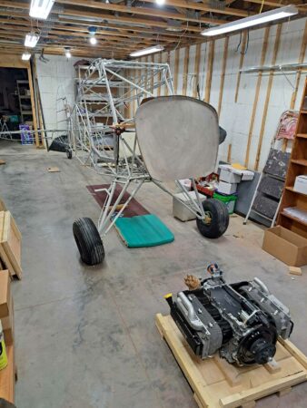
Back in Kansas, engine is waiting to be mounted on my LSA.
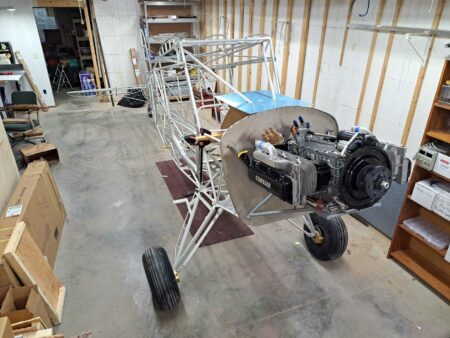
Engine mounted with William Wynne’s engine mount. The Corvair uses a bed mount.
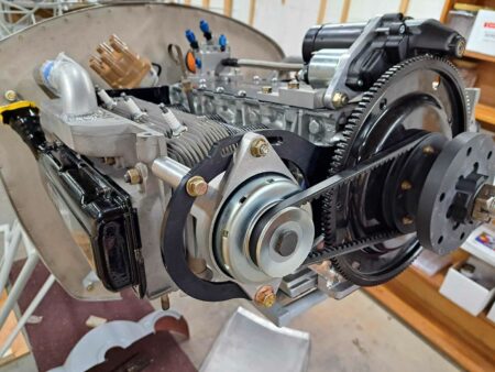
20A alternator now installed.
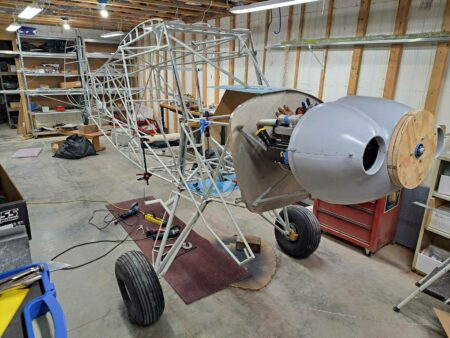
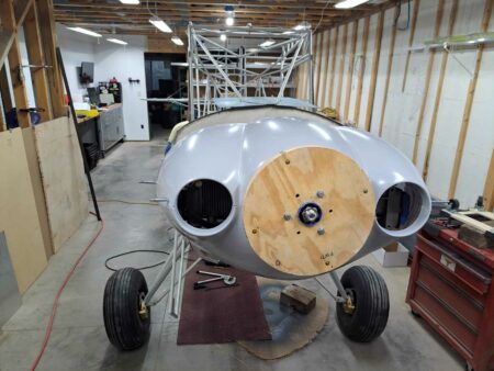
Nose bowl installed. This nose bowl is designed to use the 13″ spinner from Van’s Aircraft.
Source: 2021 Q3 Beartracks, Alan Aurthur
Link to previous articles:
Australian Bearhawk Patrol Glider Tug Called “Lucy”
Thirty-four months have gone by, and Lucy has completed just over 200 hours and 150 glider tows.
Climbing to 22000 feet, the real limiting factor is the pilot. Not only do you need a good supply of oxygen, the -38C outside air temperature means you need a good heater or very warm clothing. The other limiting factor is at 22000 ft the elevator control had reached full aft; this could be improved by some ballast in the baggage compartment or a passenger.
A few cross-country flights experimenting with prop pitch and cruising RPM revealed a few limitations with the Mazda engine. Firstly, that the mixture cannot be leaned or the EGTs rises rapidly up to over 1000C if you don’t watch it.
The fuel consumption has settled at between 11.8 and 13.2 gallons per hour and with the right pitch setting around 100kts cruise speed with around 50% throttle. The positive is that although it can burn expensive aviation gasoline it is much happier with 98 octane Mogas.
Very steep climbs are possible coupled with high climb rates and very high fuel flows. The downside is that with fuel levels below about 7.9 gallons per side the forward fuel outlet will unport and the injection pumps will suck air followed by a rapid increase in the EGTs and then rough running. The problem is not easily overcome. The header tank with the submerged pumps has about five minutes of fuel so with low fuel levels steep climb outs need to be limited to less than that. However, five minutes on full power equals a more than 5000ft climb.
Where the turbo charged Mazda engine really shines is in glider towing to more than the normal 2000 ft above ground level. Climbs with a glider on tow average 600 ft/min at sea level, this obviously reduces with altitude however at 10000 ft this is still around 350 ft/min. The average climb rate to 10000 ft was 440 ft/min.
The next step will be to see how high we can tow to; the guess is that around 15000 ft will be the practical limit. 15000 ft on a still winter’s day should produce a glider flight time of over two hours.
The real success is the Bearhawk Patrol airframe, we have had absolutely no problems and no failures in any of the kit components, our only problems have been with our custom engine installation and with a bit of luck it has now settled down. Time will tell.
Source: 2021 Q1 Beartracks
Joe Mason and his dad Mike are building a Patrol from a Quick-Build kit in Twin Falls, Idaho. They are installing an Aero Sport Power O-375 with 200 horsepower, and a Hartzell Trailblazer prop. Joe says, “We are hoping that this engine/prop combo will be a good one. At our home base we see some pretty high DA during the summer and that’s what drove us to try that larger engine.” They started on the kit in September 2018 and were painting in February 2021. The panel is built around a Dynon Skyview system and so far the paint quality looks outstanding.

Source: 2020 Q3 Beartracks, Alan Arthur, Doug Harrington and Avon Furphy

Eighteen months have gone by down in Australia and Lucy has completed almost 100 hours and 85 glider tows.

Initially the Mazda 13B rotary engine was naturally aspirated and although the performance with around 180 – 200 HP was more than satisfactory for normal flying the performance towing a 600kg (1322 pounds) glider on a 40 degree Celsius day was not spectacular.
Early on we had a problem when the engine started to consume excessive amounts of oil, there were no leaks and the exhaust was not wet and oily, what was happening was that the engine runs so hot that the oil leaking into the combustion chamber was being burnt as additional fuel. At the same time the air fuel ratio indicator was showing an erratic mixture that could not be corrected by adjustments to the fuel map. Hindsight is a wonderful thing and now we know what causes erratic mixtures.
The engine had to be removed and the rotor oil seals replaced, on a Mazda rotary that means a complete strip down. The opportunity was taken while the engine was out to fit a standard Mazda turbo charger. That sounds simple but was anything but. The engine bay configuration and the engine mount necessitated a quite radical custom installation.

Starting with the fabrication of an exhaust manifold that placed the turbo charger behind the engine in a spot that was previously occupied by dual batteries and a few other accessories.
The batteries had to be moved to the rear fuselage to compensate for the anticipated additional weight forward of the C of G.
The exhaust system and mufflers had to be completely reworked.


The turbocharger needed to be restricted to a boost pressure of no more than 6 psi, the standard turbo engine had low compression rotors; ours had high compression rotors and the advice was that this combination of high compression rotors and high boost pressure would cause seal and pinging problems. The waste gate controller was modified so that it was producing a maximum of 5.6 psi.
The next area for rework was the intake manifold and throttle body. Space was a limiting factor, so the standard manifold was cut and welded to keep the intake system as low as possible and oriented in the easiest direction for the plumbing connections.


Space constraints dictated that an intercooler could not be fitted and was probably not necessary with the low boost pressure.

First engine runs proved to be very positive, boost pressure was spot on and manifold pressure was up to 42” at static rpm. Fuel flows had gone up considerably from around 35 liters per hour to 50 l/hr (9.2 gph to 13 gph).
One of our original problems before the turbo was having to run the ground adjustable prop in the full fine position to achieve acceptable RPM in climb. After the turbocharger was fitted, we had to increase the pitch to limit the RPM.
Glider towing times before the turbocharger were in the order to 9 minutes to 2000ft chock to chock towing a 600kg glider; after the turbo the times are in the order of 6 minutes. Lucy’s tow times now closely match the times that are produced by a Piper Pawnee. Our estimate is that Lucy is producing around 240HP
Thirty hours have been completed with the turbo with no problems of any kind. One of the most common problems with auto engines in aircraft is cooling and particularly during taxi and ground operations; our dual radiators and double sized oil cooler have proved to be up to the additional heat produced by the turbo.
Where to next? With the turbo charger the obvious question is how high will it go? When the ideal day came round, a clear blue sky and almost zero wind at any altitude it was time to borrow an oxygen system from the gliding club and see how high Lucy could climb.
A couple of practice climbs to 12500 ft and 15000 ft on previous days sorted out the radiator expansion tank problems and then a full throttle climb to 22000ft answered that question. Lucy’s operation ceiling is around 22000ft where the climb rate fell to around 100 ft/min. The Mazda rotary engine performed faultlessly and even picked up RPM as she climbed, no doubt due to reduced prop drag at higher altitudes. The real limiting factor is the pilot, not only do you need a good supply of oxygen the -38C outside air temperature means you need a good heater or very warm clothing.


What next, more glider towing and cross-country flights experimenting with prop pitch and cruising RPM with an aim to reach an economical cruise consumption.
Source: 2019 Q3 Beartracks, Alan Arthur
The gliding fraternity have been talking about auto engine powered tugs for decades and despite the efforts of many they haven’t become a reality (yet), recent changes to Civil Aviation Safety Authority (CASA) regulations have made it a far more practical proposition.
A casual conversation around the bar lead to a syndicate being formed to look at a private venture to install a Mazda 13B Rotary engine in a PA 25–150 (small Pawnee). The syndicate members Alan Arthur, Doug Harrington and Avon Furphy conducted an extensive search for a suitable aircraft and finally dismissed the idea as too expensive, too much work, too many ADs and too many owners that had an inflated idea of the true value of their aircraft.
The idea changed to building a kit aircraft similar to a Piper Super Cub, also with a Mazda Rotary engine. The Bob Barrows designed Bearhawk Patrol was selected and after some consideration an order was placed for a Bearhawk Patrol quick build kit with Bearhawk Aircraft in Austin Texas. The kit was ordered in July 2016 and after a couple of months sorting out options arrived in Perth Western Australia on 29 December 2016.
A couple of days later after it had cleared quarantine/customs, a trailer ride to Narrogin saw it installed in the new hangar at the Narrogin Gliding Club for the build. The kit consisted of a steel tube frame and other welded steel tubes and fittings and lots of raw material. The instruction manual was quite basic but I purchased CDs of the build details compiled by other builders and the kit manufacturer provided hundreds of photographs of other builders projects. The basic airframe went together quite quickly and by the end of January 2017 we had the first visit from the SAAA TC Geoff Danes and the AP for the project Bill Keehner.
Avon already had a Mazda 13B engine sitting in his shed waiting for a racing car project so he donated it to the project, it hadn’t run for many years so was shipped to Rotormotion in Perth for a complete overhaul and conversion for aircraft use. Rotormotion’s brief included a target HP between 210-240 Hp.
The auto engine installation consumed enormous amounts of time as our glider towing goal meant that we could not have any problems with engine cooling at relatively low airspeeds and high power settings. Consequently we selected a twin radiator system and a double sized oil cooler. Experience during the test flying program indicates that we may have got it right.
Avon’s Mazda rotary engine was a fuel injected and electronic ignition version from a Mazda RX7. All of the Mazda fuel injection and ignition system was discarded and instead twin aftermarket EMS Stinger systems were installed driving the standard injectors and twin spark plugs. Also discarded was the heavy exhaust manifold and all the environmental systems. After initial engine runs the custom exhaust was modified to include two straight through mufflers and ceramic coatings on the engine pipes.
PSRU selection proved to be a bit of a problem, all of the toothed belt systems seem to have disappeared, the only system we could find with good reports was a geared system from Autoflite in NZ. This PSRU is available in two or three gear versions and we chose the three geared one to keep the direction of rotation the same as Lycomings. It also moved the engine thrust line up closer to the original design position. After selecting the PSRU then we were able to order a prop to match. We ordered an IVOPROP Corp Magnum three bladed ground adjustable prop of 76” diameter.
The fuel system needed to be modified to incorporate dual high-pressure injection pumps. Initially I was going to build a header tank with dual submerged pumps but in the end found exactly the setup I had planned in an auto supply catalogue at a much cheaper price. The system is now gravity feed to the header tank and high pressure to the injectors, return fuel comes back to the header tank.
The aircraft relies on electrical power for engine operation so it was quite critical that everything was duplicated; not only is everything from dual batteries to the ignition boxes selectable but we have incorporated a panic switch that can change all selections to the opposite selection with the flick of one switch. At higher altitudes you can do some fault diagnosis but when towing a glider at 100 ft you don’t have time to play around with systems.
The airframe is part covered with aluminium alloy and part with fabric; we chose to use the Oratex prepainted fabric. The Oratex fabric is quite easy to use and being prepainted has no hazardous solvents to use, the glue is a water based hot melt glue. The fabric is about 80% the weight of other fabric systems which resulted in the aircraft center of gravity being well forward requiring lead ballast in the tail. If I was to build another Bearhawk I would plan to fit the dual batteries in the rear fuselage and not on the firewall.
Instrumentation did not need to be very complex and other than the engine monitor all are round steam gauges. For the engine management system we used the MGL Extreme EMS display which has the advantage of being in the main programmable. After 19 months, 4450 hours and a lot of engine runs and taxi tests the big day arrived. Word had spread and instead of having a quiet first flight there were dozens of spectators on Saturday 15 September 2018.
The SAAA team arrived early for the final inspection, Geoff Danes and Bill Keehner did their inspections and Bill issued the Phase 1 C of A. The aircraft flies really well; it took to the air as if it was made to fly.


Alan also says: Dennis and Donna suggested that I also send you some photographs of my fool proof control lock (you can’t leave it in and go flying).


by Steve Busby, Aerolite Flight Services
The Patrol can accept engines from 115hp to 210hp. The prototype is powered by an O-360 Lycoming 180hp engine, and this is the standard choice among most builders. It is up to the builder to decide on accessories and engine configuration, e.g. carburated vs fuel injected, standard mags vs electronic ignition. The kit is supplied with a Lycoming O-360 Type 1 dynafocal mount. This mount will work on all four cylinder Lycomings except the engines that have conical mounts.
If a builder wants to use a smaller engine, e.g. Lyc O-320, then you will want to keep weight in mind when building. 180hp is very adequate for the patrol, though, as the horsepower rating is stated, you can go higher. As an experiment on an early Patrol kit, we had a 210hp IO-390 in the shop, so we test fitted it to the kit. It bolted right on to the engine mount, but being an angled valve motor, was wider than a 360. To make the cowls look right, it was decided a wider firewall would be needed. We decided right then that the required mods were not worth the extra expense, complications and weight penalty.
The same kit as mentioned above, was fitted with a 195hp IO-375 Lycoming, with dual Pmags for electronic ignition. The accompanied pictures here show that installation, but a 180hp O-360 would be very similar, the large oil cooler being the biggest change. Though the performance with the 375 is amazing, a standard 360 will meet most everyone’s needs and will provide performance beyond most builders expectations.

Source: 2018 Q3 Beartracks, Bob Triplett
Every aircraft is designed with many compromises. One has great speed or short field performance or great slow speed characteristics. I am not aware of any aircraft that has it all. When I find such a plane I will consider building that plane. Perhaps some of you know me or my plane (94RT).

I built 94RT from the kit. It has been displayed in the Bearhawk booth at Oshkosh for a couple of years. Let’s be clear, I do not work with Mark Goldberg and I have no relationship to the company. I enjoy the fellowship with the pilots who are interested in the design, with Bob Barrows, Mark Goldberg and the other regulars at the display. Besides it is a great place to get out of the sun.
This year the plane that Mark uses as a test bed to try new design features and as a demonstrator aircraft to give rides to potential customers due to a glitch was unable to make it to Oshkosh. It got as close as Hartford near Fondulac and was unable to be brought to the show. During the discussions it became apparent that another pilot was going to be required to fly the plane back to the Austin Texas area. In the course of our discussions I indicated that I might be interested in flying the plane back to Texas. After Mark considered my offer for a few days we agreed that I would fly it back.
I have a 180 hp Lycoming O-360A1D engine in my aircraft and have considered replacing that engine with the 250 hp Lycoming O-540 engine. I thought this would be a great time for me to fly behind the O-540 and compare my airplane and performance (O-360) to Marks plane.
I had never flown Mark’s plane so the first thing that I did was do a walk around to see what things I found different in his build than my own and what if any difference that might pose to me on a cross country flight. I had no one around to provide any tips or pointers and I did not want to bend Mark’s plane or add another check marked box on my insurance application.
My first observations were that there were no nav lights, no aux tanks and no landing lights. The plane has the new style B wing and the new style horizontal stab and obviously the 250 Lycoming engine. All of these features would impact my preflight planning.
Next I sat in the plane. I just sat in the plane and surveyed the differences in the layout. What was different from my panel? I closed my eyes and tried to reach for a control with my eyes shut to try to build a mental picture of things in my mind to make the plane more a part of my mental picture and make flying it a little easier. He had some unique differences in his layout. He has the throttle, prop, carb heat and mixture controls on the far left side of the panel near the opening. He likes to work those controls with his left hand and fly with his right. I have a lot of J3 cub time so after 3 landings I had no trouble adapting to this layout.
Another difference is his trim system. I have custom built my own design trim wheel with a 2:1 reduction. My trim wheel needs to travel twice as far as his to get the same effect. I had heard horror stories about the trim wheel being too sensitive and thought I have the tools to build the system and I could do it with a similar weight so I installed my own design. I can report that the factory trim system as provided is not a problem. I had no problems trimming the plane from the first flight to the final flight. I will say that since my system is a 2:1 reduction it requires considerably less force to move mine than the factory system. This difference might be accounted for by either the additional torque of my system or by the setup of the friction in Mark’s system. Knowing what I know now I would not spend the time and effort to install any type of reduction into the system. It is fine just as Bob designed it. Oh, one more thing. I took off with the trim out of adjustment in my own plane one time. Trust me you do not want to do this. The feedback in the stick is really heavy. As part of my preflight I always check the trim tab to see that it is a neutral position.
Another thing that I found different about the plane is that the panel is basic. There is nothing fancy about the panel. This is a matter of taste but if it were mine I would and have installed glass instead of steam gauges. Oh well I started with them and a basic panel, I guess I can survive. It is my opinion that Mark’s objectives are to provide a safe, simple, light design more toward all out performance. Also bear in mind that this aircraft has over a thousand hours flying as a demonstrator aircraft. Perhaps keeping the plane simple is the best choice as people will be getting in and out and cause a lot of wear and tear.
My First Flight
I decided that the first thing to do was to make 3 landings and 3 takeoffs before departing the area. I was not real familiar with the airport but we had just flown in and I had a chance to survey the area and the airport so I thought it best to check myself out in the plane at this airport before flying off somewhere to a strange airport.
As I came in with the power I could noticeably feel the power difference between my plane and this one. I came in very slow with the power and it responded favorably to me. I could feel when it was ready to fly and I was not at wide open throttle so as it began to fly I smoothly came to full power. The climb rate is phenomenal. At 200 feet on climb out I came back to 2400 rpm and reduced the manifold pressure somewhat. I climbed to pattern altitude and turned down wind. At the end of the runway on downwind I reduced power and set the plane up for landing. I had to use caution here because Mark’s plane is in miles per hour and my own is in knots. The first landing was not pretty but it was a nice landing. Remember there are a lot of differences in the two planes that I am balancing.
The second takeoff I now have more confidence in myself and the plane. I came smoothly with the throttle but carefully to wide open throttle. The plane jumped off the ground and we quickly climbed to pattern altitude. I flew a normal down wind and setup for landing as before. This time the plane began instructing me. I got a little low on final. As I added power the nose pitched up. Remember earlier when we discussed the trim and I indicated that the trim has a lot of power. As I fly my own plane I find that it is easier for me to bleed off altitude than to regain it. Also as you bleed off energy on flare it gives me some time to make a smooth flare and touch down. FLY a stable approach as much as you can. The engine has so much power that when you apply power in the landing configuration you will need to account for considerable changes in the stick feedback. After the third landing I felt that while not over confident this was going to be a fun trip and the plane was well within my skill level.
What did I learn here?
The plane is considerably heavier in empty weight than my own. The feedback in the stick is considerably heavier. It is not to the point of being annoying but you do feel the difference. Trim is even more important. Fly a stable approach as much as possible. Make your power adjustments as effective as needed but do it slowly. Be prepared to re-adjust the trim as needed. Remember those controls that are now on the left side. It requires that I take my hand off the throttle and put it on the stick, take my right hand off the stick and re-adjust the trim quickly and reverse the order. Sorry Mark I can live with it but it was not my choice. I understand his motivations. That is the beauty of the experimental plane. I can have it my way. The pane is considerably smoother. The six cylinder engine is noticeably smoother than the 4 cylinder. Mark has the new three blade trail blazer prop on this plane. He says that the prop has 20 percent more thrust. I don’t have a base line to compare the effectiveness of the prop. All I know is that the plane is a HOT ROD. It will well out perform my plane in climb out and speed.
Speaking of Speed
I flew most of the eight plus hour trip at 4500 feet. I set the engine up at 19 to 20 inches at 2400 rpm and saw fuel burns in the 13.9 to 14 gallons per hour with indicated airspeeds of about 135 miles per hour. Mark says that I could have leaned a little more aggressively, maybe able to get it down as low as 12 gallons per hour at this power setting, and perhaps a little less if I reduce the power to that of the 180 hp Lycoming. Yes I know that this does not tell us much as I did not calculate true airspeed. Remember those wings with only the standard tanks in them. I planned 2.5 hour legs which gave me a nice reserve at landing. Here is where I wished for the aux tanks. If you build with the 250 hp engine I would certainly install the aux tanks. At this speed the plane is quieter than my own. His controls are very nicely balanced and the plane is rigged almost perfectly. The engine is so much smoother than mine. It was pleasant to fly. I could trim it easily to level flight and fly it with two fingers. Yes it is tiring to fly in any aircraft for eight plus hours but I did not feel as much strain flying the Bearhawk for eight plus hours as I did riding on and making connections on the commercial plane for the return trip home.
Would I, knowing now what I know, trade my engine for the 250 hp engine? Probably not though I have not ruled it out. If I was flying on floats or spent a lot of time flying in the mountains it would make sense. The exhilaration is a real kick; I am in Wisconsin at 1107 ft. above sea level. My plane performs flawlessly at this altitude. Yes it would do better with the 250 hp engine. BUT remember that fuel flow. I burn 10 to 10.5 gallons per hour. One would also need to spend considerably more to purchase the engine and maintain the engine along with the feeding.
I love that hot rod airplane but airplanes are a compromise and I guess mine is a pretty good compromise after all. What you see here are mostly emotional evaluations and comparisons of my own plane and that of the factory demonstrator. Very little science here, hope you find something of value in this emotional review of a great plane. Thanks Mark for the opportunity to fly your great plane.
Epilogue
Well, it is September 27, 2018 and some time has passed since I flew the 250 Bearhawk and recorded my thoughts. Jared has just emailed me requesting some pictures of the plane to go with the article. I had just hung up the phone after talking with a party that had an O 540-B4B5 235 hp Lycoming for sale at a reasonable price. Yes, once you have flown behind 250 hp. the kick is hard to forget. That take off and climb performance is hard to resist. But I did not bite the bullet. I began to weigh the work ahead if I made such an investment and decided that if I really want that performance I would be just as far ahead to build a new B model plane with that engine in it. My panel is all electric and I just don’t like chopping into the systems to modify it to fit the needs of the 6 cylinder engine, new cowl, new engine mount, new exhaust system and a new induction system all need to be redone. I can do a better job knowing what I did on this plane. I keep telling myself that the plane performs flawlessly in the area where I live. I have two less cylinders to maintain. My engine has all new components in a freshly certified case with just 180 hours. Just look at the maintenance room that I have behind that engine. The fuel burn is less but I have to admit that I do see slower cruise speeds and somewhat less performance than the 250 hp engine. The 180 hp Bearhawk is a fine compromise. Either way you will not be disappointed that you chose to build the Bearhawk. All of the new features and the additional factory work make the plane easier to build and get professional results. Thirty minutes of work on a new plane would equal 2 hours of time that I invested in building this plane.
Purchase your engine as late as you can. The longer you store the engine, the more susceptible it is to corrosion, damage, or obsolescence. You’ll need to have an engine to build the cowling, but if you are lucky enough to have access to a core, it will do just as well as an airworthy engine. There are some benefits to deciding on an engine plan early, such as being prepared for purchase if a good deal comes along, and planning the supporting systems accordingly.
Bob Barrows designed the Bearhawk around a 4-cylinder angle valve Lycoming O-360 that produced around 170 horsepower. His second prototype used the parallel valve Lycoming O-540 producing around 235 horsepower, in part just to see how it would do. The airplane is a great performer with the smaller engine. With the larger engine, it has been described as “barbaric.” There is a natural tendency to think that bigger is better when it comes to engines, but this is not always the case with airplanes. Don’t let your ego make the decision. Bigger engines are heavier, and often require additional system requirements that further compound the weight gain. Read more about this topic in the Bingelis books. Bob prefers to see the engine weight kept under 400 pounds. Continental 0-470/520 engines weigh a little more than that, so he has adjusted the design of the motor mounts for those engines.
To oversimplify, here are some rules of thumb: if you live in a place like the western United States where you’ll frequently be climbing to density altitudes above 10,000 feet, or if you’ll be regularly flying at weights above 2200 pounds, lean towards the larger engines. If you’ll not be regularly needing these kinds of performance demands, you can save around $10,000 in initial cost and 100 pounds of empty weight by using a smaller engine. Ongoing cost savings will include reduced fuel burn during takeoff and climb and reduced maintenance needs of the 4 vs 6 cylinders. Both configurations will burn essentially the same fuel in cruise at the same airspeed, but if you cruise both at a high power setting, the bigger engine will deliver around 15-20 extra knots for 3-5 more gallons per hour. Back at 65% power, the average fuel burn of a 540 is approximately 12.5 gph, versus 9 gph for the 0-360.
Drag increases noticeably with speeds above around 115 knots, and the resulting miles per gallon will reflect this.
Regardless of your choice, be prepared for a dizzying number of variants, some of which may seem like a bargain. They may indeed be a bargain, or they may be something totally unusable that will be expensive to reconfigure. The safest bet is to stay near the center of the envelope, so to speak. Here are some tips to help you narrow down the choices.
Consider what you’ll need for accessories, since this may narrow down the engine choice. Although not a requirement, a constant speed propeller is highly recommended, and will make it possible to better utilize both ends of the airplane’s speed envelope. If you plan to run a constant speed prop from the beginning, or if you think you might like to ever install one, consider this in your engine shopping, to ensure that you have the appropriate provisions for a prop governor and a hollow crank.
Many builders consider mounting an alternator on the vacuum pump drive pad. These alternators are available in a range of sizes and can serve as a backup to a front-mounted belt-driven alternator, or as the only alternator. Your choice here will determine whether you’ll need to have a vacuum pad and drive.
Most carbureted Bearhawks use gravity fuel systems. As designed, the system delivers adequate flow for engines in the recommended range, and will not require an engine-driven fuel pump. Builders choosing fuel injection will require an engine-driven fuel pump and the associated provisions in the accessory case, and likely other components aft of the firewall.
As far as ignition is concerned, there seems to be a consensus to avoid the varieties with a single magneto drive. Beyond that, builders have used traditional mags as well as the experimental electric options with good results.
Choosing a 4-Cylinder Lycoming
First, limit your search to those with Type I Dynafocal mounts, since these are the only ones that will fit the engine mounts provided by Bearhawk Aircraft. Bearhawk Aircraft does not support conical mount engines.
Some builders shop in the 0-320, 150/160 hp size, but those builders must pay particular attention to keeping the airplane light. Kept reasonably light, the overall performance will be better than a C-172 by a measurable amount.
The 180 hp 0-360 engine is probably the best choice for 90% of BH builders. It is available new from Lycoming (with special OEM pricing for kit builders), in various experimental engine kits from other suppliers, and is ubiquitous in its use in many applications. Some of the alternatives include Superior and Continental (which has recently bought ECI/Titan).
With 170-200 HP, the takeoff and climb performance will be on par with a Cessna 182, although cruise will be lower, around 110-115 knots. The wide deck and narrow deck options are both acceptable, but look to the angle-valve variants rather than the parallel valve. These engines would have been fuel injected in their original configuration, but with guidance from Bob many Bearhawks have flown with these cylinders and a carburetor. When Bob builds an engine like this for the 4-place Bearhawk, he uses a rear-intake sump and makes a special 90-degree adapter to move the carburetor aft. This puts the carburetor in about the same place as it would be for a 540, and makes the exterior intake much more streamlined. This is possible because the 4-cylinder engines leave cavernous space between the engine and the firewall, since the prop mounts at the same station regardless of the engine. Within the 360 variants, the final horsepower will be determined by the compression ratio. This will also determine the minimum fuel grade. A ratio in the 7:1 neighborhood will deliver around 170 hp with the ability to run 87 octane fuel, assuming you can find it without ethanol. Ratios near 8.5:1 will deliver around 180-190 hp with the ability to run ethanol-free 93 octane fuel. Higher ratios will require 100LL, but will deliver closer to 200 hp.
Adding fuel injection makes it an IO-360. This adds weight and complexity, and will provide a slight power increase.
There are a few 4-cylinder variants that increase displacement and horsepower. One is the IO-390, which produces in the neighborhood of 210 hp for a cost premium of $15,000-$20,000 over the angle-valve O-360. This variant has flown successfully in multiple Bearhawks. Another is the Titan IOX-409, which is rated for an astounding 230 hp, but at an equally astounding price. They also offer the 370 and 375 “Stroker” engines, which have parallel valve cylinders making 185 – 190 HP with a carb and 195-200 HP with fuel injection. With any engine choice, but especially with the less common choices, it may be beneficial to talk with a Bearhawk builder who has successfully implemented the design, which will help identify any required deviations from the basic configuration.
Choosing a Six-Cylinder Lycoming
The 0-540 series of engines are heavier, but provide an increase in overall performance that is hard to believe. However, nothing is free, as the useful load will go down at least 100 pounds. Experience shows that it may go down as much as 200 pounds if the larger engine inspires the builder to also install auxiliary fuel tanks (30 pounds), fuel pumps, etc. Choose a parallel-valve 0-540, not an angle-valve. The angle-valve engines weigh over 80 pounds more than the others. Whether it is a wide deck or narrow deck engine makes no difference. You’ll find variants producing 235 hp, 250, hp, 260 hp. 235 hp engines (“B” series) are lower compression engines capable of burning automotive fuel. They are cheaper and easier to acquire, and performance is still unbelievably good.
Hartzell constant speed props can only be used on O-540 A4XX, 0-540-B4XX, -J3XX engines. All other series of 540s, which are usually early engines, must be modified with heavier crank shaft counterweights or use a McCauley prop.
All 540 Lycomings can be easily modified with the heavier counter weights. They can be installed without disassembling the engine, by removing cylinder No. 6. The parts and instructions are available from: Johnston Aircraft Svc, Inc, P.O. Box 1457 Tulare Municipal Airport, Tulare CA 93274, 559-686-2161, www.johnstonaircraft.com.
There are two types of mount ears on 0-540s. The Type I has 1 3/8” holes the Type II has 2” holes. These determine which motor mount you’ll need from Bearhawk Aircraft, and which motor mount rubbers to buy. The mount lugs bolt to the engine case, so they are interchangeable, but expensive.
Continental 360/470
The six-cylinder Continental 0-470 engines represent good buys on the used market and are smooth running, well known engines. They are usually heavier than 0-540 Lycoming, and use McCauley props. The output will vary from 215-285 hp, depending on the output. The IO-470 is 260 hp, but there’s the probability of firewall interference with the longer fuel handling unit at the rear so it’s not recommended. The basic cowling design was for the Lycomings, so modifications will be required. These engines use an entirely different mounting strategy, and variants other than the O-470 will likely require custom mount fabrication. We say that the O-520, being heavier than the O-470, which is heavier than the O-540, is not a viable engine for the Bearhawk.
Automotive Engines
Bearhawk Aircraft does not provide any support services for automotive conversion, so you’ll be designing your own motor mount, cowling, etc. You are building your own airplane, and it is your experiment. It is your own choice to make, but consider the following. The automotive engines can seem seductive. What’s not to love about an initial price that is 1/10th that of a Lycoming? Traditional airplane engines were designed many decades ago, so surely there is the technology for making better engines now? Sometimes a builder starts down this path and feels like he has stumbled upon a secret alternative that nobody else knows about.
The big issue with auto engines is that we must not just consider the engine, but rather the overall task of powering the airplane. We often hear in hangar discussions that airplane engines are really simple. In some ways, they certainly are- but in many ways, they are not. Every aspect of their configuration has been carefully considered and engineered over decades of use. Design choices are not arbitrary- they are almost all based on making the most reliable overall powerplant possible, applying lessons learned from failures large and small. The same applies to engines designed for cars, perhaps even to a greater degree. The folks at Subaru have painstakingly engineered every detail of their engine, how it relates to every other aspect of the car, and how it is used in that application. But how does that application relate to the airplane environment? Airplane engines are designed to run near their maximum RPM for hours at a time. Car engines are designed to operate at maximum RPM for only a short time. When it comes to cooling, the airplane engines applicable to the 4-place Bearhawk are air-cooled. Most car engines are liquid-cooled, and are going to require a radiator. Where is that going to go? The airplane engines are direct-drive, turning the prop at the same RPM as the crank. Will the auto engine be able to deliver the performance you’d want in that configuration, or must it be geared down? How is fuel to be metered, and ignition to be delivered? How robust are those systems, and what is their failure mode? Do those devices give warning of failure before they completely quit? What kind of propeller choices are going to be available for the car engine? How hard is it going to be to service the airplane custom components when you are away from home and have a problem? What about insuring the plane when it is time to fly? What about resale value?
All of these questions get to the broader goal of providing a total powerplant solution. Mounting, cooling, fuel metering, intake, ignition, exhaust, and power transmission may sound like just a few little things to sort out, but experience shows that these are actually really big things to sort out. An auto conversion adds at least a year to the construction time, apples to apples. The majority of Bearhawk builders who have stuck it out and flown with auto engines have later switched to traditional airplane engines after their plane was flying. There are one or two notable exceptions, and for anyone still considering an auto engine, we strongly encourage you to get in touch with one of them.
Propeller Considerations
Most people use a constant speed propeller on the airplane, though it is not a necessity. A fixed pitch prop will save around thirty-five pounds and many thousands of dollars.
The downside to using a fixed pitch prop is that, of necessity, it will be a compromise in most parts of the flight regime. Because the Bearhawk has such a wide speed envelope, regardless of how you have a fixed pitch prop pitched, it will be slightly wrong at least part of the time. For example, one Bearhawk with a fixed pitch prop had a great takeoff roll and climb, but required a nearly immediate throttle reduction at level-off to prevent exceeding maximum RPM limits. With a constant speed prop, the throttle can wide open, or anywhere else, delivering much faster cruise speeds when desired. Special pricing is available on most props for kit builders when the props are purchased through Bearhawk Aircraft.
Source: 2001 Beartracks, Mike Meador and Bob Barrows

Many builders are at the point where they REALLY have to start thinking about an engine. This is the first in a series of articles about the choices that you have with Lycoming engines. I know that many will not use Lycomings but I think that this information will be useful no matter the type of engine that you choose.
The Lycoming engine comes in many different model codes. Because you are building an experimental aircraft you are not required to go with a specific code. You can build your engine the way you want or adapt the Lycoming you picked up at the swap meet to work in your airplane.
The first choice that you will want to make is displacement. The Bearhawk can use just about any Lycoming between 320 Cubic Inches (C.I.) and 540 C.I. Before you determine your horsepower you need to make up your mind if you are going to set up for auto fuel or 100LL. The basic 0-320 can run on auto fuel and produce 150 hp @ 2700 rpm, but if you raise the compression and run 100LL you now have 160 hp @ 2700 rpm. Another option that you have is running up the rpm if you are using a constant speed prop. This will shorten the life of your engine if used too much. Perhaps the best set up for auto fuel is the 0-360 170 hp engine that we run in the Prototype Bearhawk. We have BIG 200 hp angle valve cylinders running Turbo-charged pistons and normally aspirate with a standard carburetor. This lowers our compression ratio so that we can run auto fuel. We can turn up the rpm and get 180+ hp out of the engine for short periods of time with no ill effects due to the large mass and superior cooling characteristics of the angle valve cylinder.
The next decision is Wide Deck or Narrow Deck. The WD engine is the current production model for Lycoming, it differs mainly in case and cylinder design. The WD was developed to stop fretting and case cracks from forming in the higher horsepower engines. It was later found that the ND cases could be modified with dowels and made just as strong and reliable as the new WD cases. The advantage of the ND case is its lighter weight and usually lower cost. New parts are available for the ND and are not really an issue with this design. The WD is a good choice in that is an evolution of the ND case and is the newest and best supported product from Lycoming.
Having decided on displacement, and deck you now need to choose a mounting style. The steel tube fuselage design of the Bearhawk makes it very versatile in this area. You can use the Conical, Dynafocal I , Dynafocal II or the bed mount. Your primary choices will be between the conical and the dynafocal I. Generally the dynafocal mount will cost more for the case and the motor mount. The advantage of the dynafocal is realized at start up and shut down because it vibrates less in these areas. At higher power settings there really is no difference between the two. The conical mount is acceptable for use on the Bearhawk and may be, in many cases, cheaper to obtain. The dynafocal II mount is a bit of an oddball but useable. You must use four spacer disks between the case and the mount for it to work properly – if you get one of these cases be sure to get the disk also. The bed mount is used on a couple of the older Lycoming designs (0-435) and a very few of the newer models.
Now comes the question of constant speed. The case and crankshaft that you choose will determine its suitability for a constant speed propeller. There are several O-320s and a few 0-360 that cannot accept a constant speed prop. You do have the option of setting the engine up initially for a fixed pitch prop and add the constant speed at a later date. Once the engine
is assembled it may be too late to swap over, if you have not made provisions for this change.
Well – you have picked your case out – you know your displacement, if it is a Wide Deck or Narrow Deck, the type of mount it uses and if you are going to use a constant speed propeller. Seems like you are on your way to your Bearhawk Lycoming. In the next installment we’ll discuss the rear accessory case, the oil pan and look a little more at the cylinder choices that you have. Later we’ll look at Fuel Injection vs. Carbureted and alternate types of ignition systems.
Regardless of the engine you choose you should become an expert on it. Get the overhaul manual, parts book and whatever else you need to educate yourself about your particular powerplant. You may find a great deal on an engine but not know if it will work on your Bearhawk. If you can learn just a small amount about what to look for you can make an informed decision and avoid an expensive mistake.