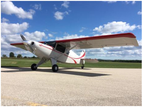
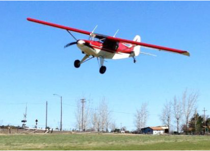
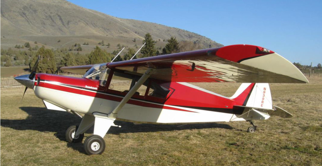
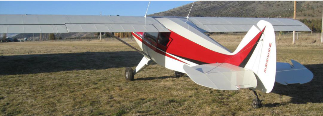
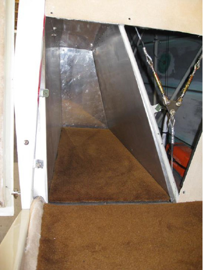
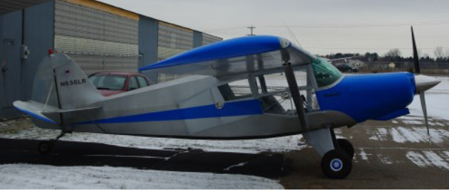
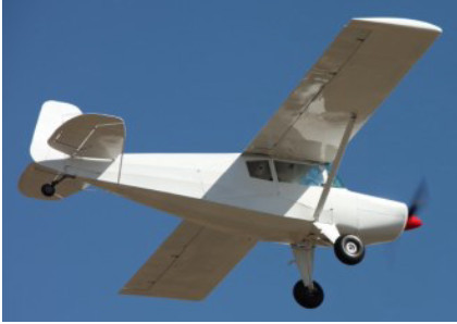
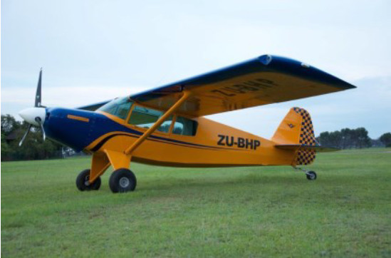
Bob Marek’s Bearhawk N156RM

Source: 2001 Beartracks, By Bob Marek #019

I became interested in the Bearhawk after reading an article in the October 1995 issue of Sport Aviation. I soon ordered a set of plans and received set #019. I put in an order to Airparts for the aluminum and an order to Dillsburg for the steel tubing and sheet. I took about two years of building to complete the wings.

In the summer of 1997 I retired from dairy farming. I built a new house and a hangar and was able to get back to work on the Bearhawk fuselage. Bob Barrows told me of the availability of a low time Lycoming 0-360 with a prop and a starter. I purchased the engine and replaced the starter with a light weight Skytec and also added a Nipon Denso 55 amp alternator. I located the battery under the front left seat.

After completing welding up the fuselage during the summer of 2000 we attached the wings and tail feathers and ran all of the cables to the control surfaces.

With much help from my better half Jeanie and a friend from Chapter 509 that is also building a Bearhawk we were able to get the covering and painting done before the weather got too cold last fall. Poly Fiber system was used to cover, with Aerothane on the metal and Polytone paint on the fabric. On final assembly N156RM weighed in at 1192 lbs with electrics and no back seat. I hope to get FAA inspection and the first flight this spring.

Weight and Balance for N156RM

Sample Weight Arm Moment
Left Main 553.5 -3.25 -1798.9
Right Main 545.5 -3.25 -1772.9
Tail 93 199 +18507.0
Front Seat 200 14 +2800.0
Fuel 20 gal 120 24 +2880.0
Total 1512   20615.0

C.G. = 20615.0/1512 = 13.63

% Chord = 13.63/66 X 100 = 20.6%


N33RB Update from 2000

Source: 2000 Beartracks, Bob Barrows

The second BEARHAWK is now up and flying and doing very well.

Construction on this BEARHAWK was started in October 1996. The final F.A.A. inspection was October 19, 1999. Taking out the time spent on the Alaska trip and Sun N’ Fun and Oshkosh trips, building time was about 2 1/2 years. I attempted to do most of the work myself but did require Mike’s help about 5% of the time for operations requiring two people.

I did not keep a good track of the hours spent but averaged about 3 hours a day 5 days a week, which is about 2000 hours. This includes building the engine and the time spent on the propeller.

Cost is not relative since many of the materials were on hand from my shop supplies.

This BEARHAWK, N33RB, is set up with the Lycoming 0-540 260 HP engine, turning a three blade Hoffman prop with non-standard blades. The airframe is built to plans with the utility door system option. No back seats are currently installed as I plan to mostly use this aircraft for cargo hauling of engines and engine parts. I did install the thicker 3 /16″ windshield.


Test flying to date, Jan 5,2000, a total of 18 hours is as follows:

Speeds to 160 MPH

Stalls with little or no power. Stalls seem to be normal at all C.G. range placements. Breaks are straight ahead with no wing drop off.

Longitudinal stability is positive at forward C.G. and drops off to neutral at max rear C.G. loading.

Yaw stability seems normal with minimum adverse yaw and good strong rudder authority for slips.


Indicated Airspeeds to date are charted below.

RPM MANIFOLD
PRESSURE
AIRSPEED (MPH)
1800 18″ 116
1900 19″ 122
2000 20″ 128
2100 21″ 135
2200 22″ 142
2300 23″ 148
2400 24″ 155

Tests were conducted at 3000′. Temperature range was 50-60 degrees Fahrenheit.

Landing speed indicated at touch down is under 40 MPH with 20 gallons of fuel and a pilot. Take-Off speed as above is at 40 MPH indicated. Take-Off distance is about 200 feet on grass and quite a bit less on a hard surface.

Thrust test shows 1200 lbs. at 27″ and 2700 RPM.

Landings have been made on both grass and blacktop with good control characteristics in all conditions to date.

I am using a tail wheel of the same construction that I designed and built for the prototype with a few modifications to use a 10″ O.D. tire in place of the standard 8″ size.

The landing gear was built to the drawings and causes the nose to set up somewhat higher than the prototype. This reduces the taxi visibility over the nose some but gives more prop clearance for larger diameter propellers. This also increases the angle of attack of the wing for take-off and three point landings. Over the nose visibility is as good as the prototype during flight.

Tests indicate that the engine thrust line (crankshaft center line) could be lowered 2″ parallel to the aircraft centerline if desired.

With the aircraft level as related to the lower longeron datum, the 80″ diameter prop has 15″ of ground clearance. 12″ is considered nominal for tailwheel aircraft of this size.

Bob Barrows and his two BEARHAWKS at Barrows Airfield.

The 260 HP BEARHAWK continues to fly very well. I am experiencing very smooth operation at 1900 RPM and 19-20 inches MP (lean). This seems to be the power setting that gives the best economy and reasonable cruise speed at 120 – 125 MPH. fuel consumption is about 1 – 2 gallons an hour more at the same airspeed in the Prototype.

The New Wings Are On N6890R (1997)

Source: 1997 Beartracks, Bob Barrows

I am glad to report that the new set of plans built wings were installed last month. The BEARHAWK flies even better than with the old prototype wings. N689OR flies a little faster (about 4 m.p.h.) and the one degree dihedral allowed for hands off stability with no adjustments needed. Initial tests were performed such as dives (up to 180 m.p.h.), entry into spins and various types of stalls. All tests have gone extremely well. Stalls are soft with no wing drop off and under full aileron and rudder control.

A new weight and balance was performed before the initial test flight and is included here. It seems like airplanes in development always gain weight, and the BEARHAWK is no exception. With new tires, balanced aileron and elevators, new tail strut bracing and thicker wing skins all added during development, show up on the scales.

I am recommending that in your building sequence that after the wings are finished that you next construct the tail group. ~GOD SPEED & QUALITY FIRST~ Bob.

Engine Static Thrust Tests

The BEARHAWK team was curious as to just how much thrust the engine and propeller combination was producing. Bob built a thrust meter and we tested it – an amazing 750 1b of static thrust was measured. In our quest to find the ideal engine and propeller combination, we have been testing every airplane that might land at the airfield. Below are our results so. Testing is continuing so look for more results in future newsletters!

The above graph is only an estimate of the static thrust that could be produced by that particular airplane on that particular day. It is meant only to serve as a rough estimate of engine and propeller power. All the above engines are Lycomings. Thrust is in pounds.

More Thrust Test Data

Here are more real world engine prop combinations. This data was gathered in a nonscientific way. The data represents only the particular thrust on that particular day that the aircraft could produce. We have not had the opportunity to test an automotive conversion that has the horsepower necessary for the Bearhawk.

AIRCRAFT DATE ENGINE R.P.M. THRUST H.P. PROP
Bearhawk (retest) 06-14-95 Lyc O-360 2800 170 C/s 75.5
Super Cub PA-18 10-25-95 Lyc O-320 2600 150 74/56
Maule M-5 Rocket 02-25-96 Lye 0-360 2600 180 C/s 76
Wichawk 07-05-96 Cont O-470 2250 213 84/56
Super Cub PA-18 08-22-96 Lyc O-320 2500 150 74/?
Pietnpol 09-29-95 Ford Mod A 1850 50+ 76/40
J-5 Piper 10-01-94 Lyc O-290 2250 125 74/49

*Re-test at new RPM and new standard cam from Superior.

Cowl Air Pressure Testing

Source: 2015 Q3 Beartracks, Jared Yates
Readers may recall Bob Triplett’s reference to measuring air pressure differential under the cowl by connecting tubes to a mechanical airspeed indicator. There is a great article on this topic by Jimmy Tubbs from ECI. This article is so useful because it brings quantitative measurement to a topic that is often relegated to intuition and guessing. Bob spoke about wanting to test his pressure differential to narrow down the cause of a high CHT. In my case, I’m interested in diagnosing a high oil temperature. Bob Barrows suggested that I measure the pressure differential on the front and back of the oil cooler, to see if it is getting adequate airflow. I already have reason to believe that it is getting good oil flow.
The concept is that for air to flow, there must be a pressure differential. For example, Lycoming has provided that a top/bottom pressure differential of 6.5 inches of water should be considered a minimum to adequately cool the O-360 in cruise. What does water have to do with any of this? It’s just a measure of pressure. A certain volume of water will have a certain weight, and when water settled in the bottom of a U-shaped loop of tubing is subjected to air pressure, it will move up or down. Our altimeter settings are delivered in “inches of mercury,” but any liquid can be used to measure air pressure. We aren’t talking about cubic inches of liquid; we can cancel out the width and diameter dimensions, because they are the same on both ends of the loop. The more dense the liquid, the smaller the movement of the liquid, and thus instrument– so that’s one reason why mercury has been a popular choice for barometers.
When it comes to measuring pressure in a bouncing airplane, mercury is sub-optimal for several reasons, so maybe that’s why Lycoming provides the number in the more convenient “inches of water” unit. Airspeed indicators are similar to barometers, except that instead of measuring pressure relative to a standard (that’s what an altimeter does), they measure pressure relative to two sources. Usually those two sources are pitot and static, but it will gladly measure whatever one connects to it. This means that an airspeed indicator can also measure pressure differentials in the cowl. Folks who have been building airplanes for a while probably have airspeed indicators sitting around, but I didn’t. I posted a question to the Matronics Aeroelectric list to see if anyone had a suggestion for a device that could measure low air pressure, and I learned that I could actually solve this problem on my own, by building a manometer. Contrary to the name, this isn’t a device that measures machismo- that’s a stud finder. Rather, it’s just the name for an instrument that uses a column of liquid to measure pressure.
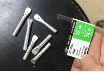
15q3vTo make the manometer, I purchased a 20 foot roll of clear vinyl tubing from the hardware store, with a 3/8 OD and 1/4 ID. I used some very thin scrap aluminum tubing to create some piccolo tubes. This tubing is available at hobby shops, and occasionally at big box home stores, but leftover brake lines might work well too. This task only requires two piccolo tubes, but I had plenty of stock and got a little carried away making extras. I smashed one end in a vice, and drilled several unorganized 1/16” holes. The goal is to create a static air source at the desired measurement site, and the piccolo tubes help negate possible errors created by moving air over the end of just a plain, squarely cut tube end. This is related to why we put static ports on both sides of the fuselage.
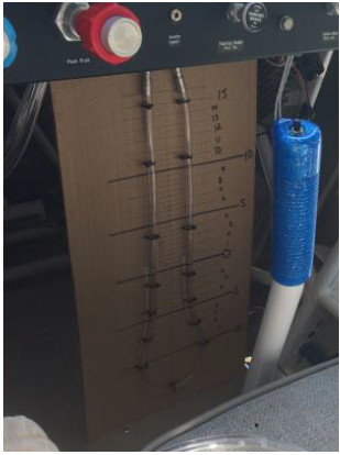
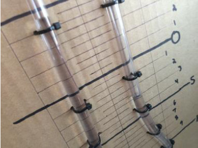
15q3wI sourced a piece of non-PMA cardboard (homebuilding has its advantages) and marked graduations in 1/2” increments, with small 1/4” lines. In retrospect, it would have been better if I had numbered the whole inches instead of the halves, but it still worked fine. I used small wire ties to attach a loop of the tubing to the cardboard, and added some small aluminum splicing tubes at the top. In theory, one could run a single tube all the way from the top of the engine, into the cabin, around the loop, and back out to the underside of the engine. I didn’t want to do it this way because it would complicate adding water, and because I wanted to test several differentials on a single flight. This required running a four labeled lines back to the cockpit, which I could connect to the manometer one pair at a time. To get the lines through the firewall, I disconnected the duct from the heat muff to the cabin heat box, opened the cabin heat valve, and ran the lines through there.
15q3xI did the flight testing by myself, but it would also work to have someone else to help with the readings. As always, the first priority is to maintain control of the airplane, and not get distracted with science experiments.
Between the top of the engine and the bottom, I found a difference of 4” in climb, and 7” in cruise. On the ground with 1700 RPM, the difference was 3/4”, and in flight at idle and 70 knots the difference was 2”. These meas-urements and my CHT indications agree that I have plenty of airflow for cylinder cooling.
15q3yI disconnected those lines and connected lines from the front and back of the oil cooler. In climb, cruise, and descent I read 4, 6, and 3.5 inches. To put those numbers into more familiar units, 5 inches of water equates to 98 knots on an airspeed indicator, or .18 psi. These are very low pressures.
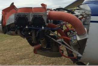
Next I measured the difference between the top of the engine and the front face of the oil cooler. This would show how much of a loss I had just in getting the air from the high pressure area to the cooler. In climb, cruise, and descent, this showed a steady 2” in all phases. In climb, that’s half of my pressure differential, and 1/3 in cruise. Next quarter I’ll have de-tails on the corrective action. Until then, I’ve included a photo of the old installation in case you’d like to make any guesses. This method would be great for sizing cowl inlets and outlets, and deciding if remedies like cowl flaps or louvers are required for a particular installation.
15q3z

The Story of Larry Sullivan’s New Bearhawk

Source: 2015 Q3 Beartracks, Larry Sullivan
15q3kKit number 98 arrived from Texas in November 2007 and we set up shop in the hangar at HXF in Hartford WI. My building partner Tom Brown, was a pilot for Midwest Airlines out of Milwaukee and he had identified the Bearhawk as a plane worthy of our investment of time and money. He has a hanger at HXF where he kept his father’s Cessna 421 and it was and ideal location. (60’ x 60’ with heat and a toilet). Little did I know the marathon I was beginning.
Neither Tom nor I had any building experience although I had worked on some cars and motorcycles and built a couple of houses and furniture for my kids. The first year was one of sporadic progress on the tailwheel, struts, floorboards, and tail feathers. Nothing requiring fabrication. By the end of 2008 the crash had occurred and Tom had been laid off by Midwest Airlines resulting in major life reassessment. We both had kids in elementary and High School and little progress was made.
Even in that first year, despite very little progress, I began to get the sense of the constant focus the project demanded. How it pulled at me every free moment and when falling asleep at night. From one small task to the next, each requiring a phone call, time on the web, or just visualization of how things go together, it was always on my mind.

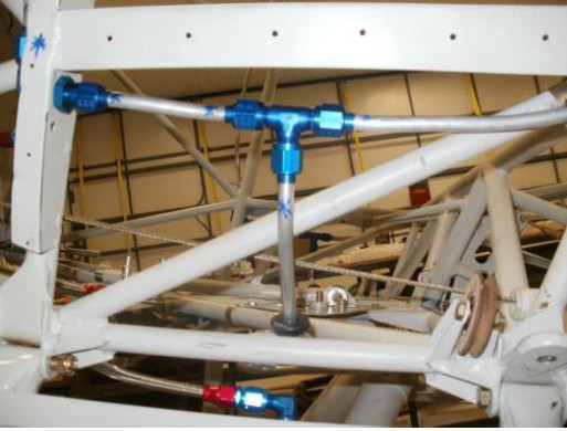
Larry's fuel line routing

Larry’s fuel line routing

Unfortunately life got in the way. My kids were finishing high school and I was on call most of the time. Tom got a sales job that took him away for most of the week. The project sat there for three years without any attention. I even put together a flier to sell the brand new Lycoming 390 engine we had purchased in late 2008. Then I acquired a partner and my call responsibilities were reduced. I had told so many people that I was building an airplane and I had had the dream in my head for so many years, I just didn’t want to give it up. I asked around the Hartford airport to see if there was anyone who might be willing to help me get started in earnest and guide me.
Fortunately, I met Marc Stamsta, a skilled craftsman who builds vintage wood airplane wings and spars for a living (www.maxaero.net) and he was willing to help me get the project going. I bought Tom’s share of the project and proceeded solo!
Marc met with me each Thursday and we tackled the wings first. I learned to squeeze and buck rivets and shape fuel and pitot lines. Despite having purchased the Wicks “hardware kit”, few of the bolts seemed to be the proper length and turnbuckles were not quite right half the time. This was one of the most frustrating aspects of the build. I had to hunt for the correct piece of hardware or thimble or cable. The “1,100 hour estimated build time” was quickly whizzing by.
15q3mHanging the wings met with near disaster when the drill bit became jammed at the root when drilling the hole to final size. Fortunately we were able to free it without damage. As with each part of the kit, we were impressed with the precision and quality of the kit. Everything seemed to fit together well.
It was on to the fuselage and I took on the fuel lines first. I made a slight modification in the route, and Bob indicated he saw no problem. Instead of bringing the rear line all the way forward of the doorframe, I routed the forward line back to meet the rear line below the door about even with the front of the seats. This allowed me to put the selector valve more aft next to the flap handle, the gascolator is aft of that and is more easily accessible behind the left landing gear.
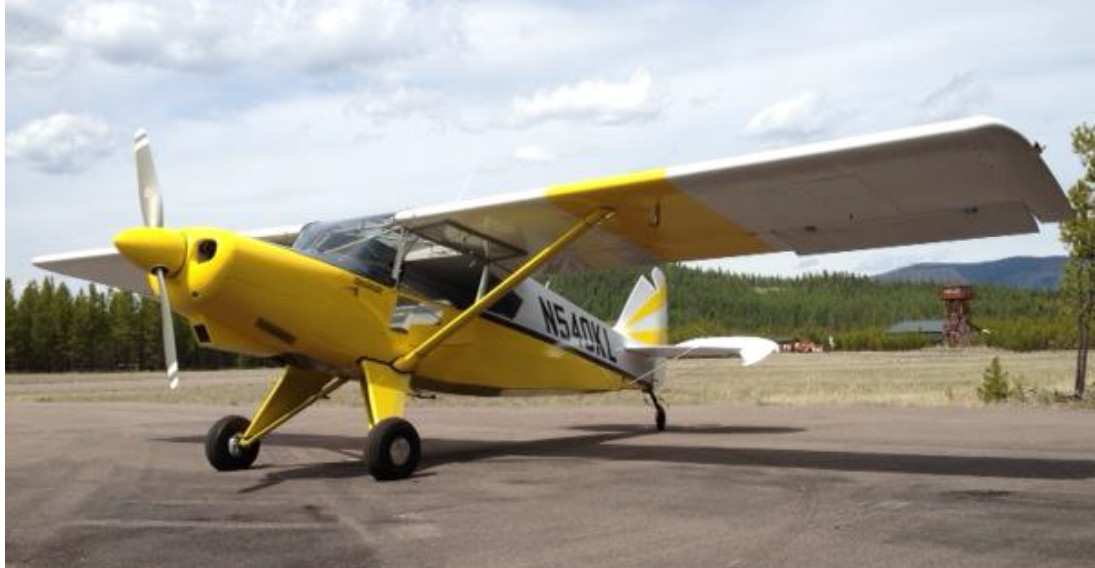
15q3nI chose to use a new fuel-injected Lycoming IO-390 EXP engine with 210 HP, and a Hartzell 80” constant speed prop. The hope was that it would provide an excellent balance of power and weight. I saved 100 pounds over the 540 and gained 30 HP over the 360. For the build itself, I’m thankful I went with the four cylinder as it provided a huge space between the engine and the firewall to fit things and route lines and cables. As a novice builder I think it would have been much more difficult with the 540. The one major disadvantage is that the #1 and #2 cylinder intake manifolds did not fit into the cowling, requiring modifications. Thus, the blisters on my cowl. I found some old Travel Air valve covers that worked very well. In retrospect, I probably would go with a standard 360 for simplicity.
15q3oI used a baffle kit purchased from Glasair, for use on their Sportsman model with the 390. Since my throttle body is horizontally mounted in front of the sump, the baffle kit goes down under the throttle body so that the entire area behind the nose bowl is pressurized. I have no alternate air or cowl flaps. My exit opening is less than the standard and although I put a lip on the opening, I’ve been trimming it back because even in 80 degree humid weather here in Wisconsin, my oil temps been 180-200 and CHT have been 325-350 max.
I used Vetterman’s crossover exhausts. Clint provided excellent sup-port, was easily available by phone and made some modifications at no charge until it was right. I needed to add their 4” extensions to direct the exhaust further down as it was really fouling my struts and underbelly without them. I have been told by others at HXF that the plane has a very distinctive (bad-ass!) sound.
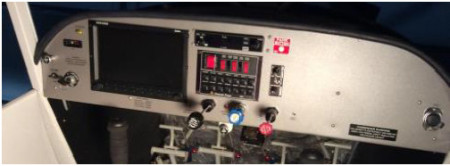
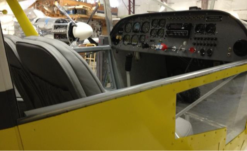
15q3pFor the panel I chose the Dynon Skyview 10” monitor with their transponder, ADSB, engine monitoring system, GPS, heated pitot with AOA, and backup-battery. I took a seminar put on by Dynon at EAA prior to installing the system. I’m learning as I go and have had excellent support. Everything has worked as advertised. Rather than individual fuses for my electrical system I chose the Composite Designs Radio Stack power panel, which included the Master and Alt switches, Radio/Nav/Strobe/Fuel Pump/Landing Light switches and 14 breakers. It made the wiring so much easier and Wayne went above and beyond to give me some overall wiring advice. I used the ICom IC-A210 radio, and PS Engineering PM-1000 II four-channel intercom.
I enjoyed the wiring aspect of the build. I’m proud that I had only two issues, easily fixed with entire electrical system, despite completing it without any interim testing. The D-pins in the ADHRS connector cable were loose and had to be pushed in, and with the transponder and ADSB, I connected the TX to TX rather than TX to RX and had to reverse them.
15q3qN460K is covered with the Polyfiber system. I also used it for my seat frame supports. I painted it in a paint booth at Tom’s hanger (where I was building) that he had used for a work-related project and allowed me to build out to fit the Bearhawk. I had hoped to have my three children participate in the build with me but you can lead a horse to water… My daughter Caroline did help by welding together two rotisseries for mounting the wings and fuselage for painting and covering. They worked beautifully. I could wheel the fuselage and wings into the booth and easily rotate them as needed.
I used PPG Aerospace Desothane topcoat and Desoprime epoxy primer. The EAP-12 Desogel non-chromate adhesion promoter was very easy to work with. Rather than using the toxic Alodine products, this just sprayed on with a spray bottle and then was dabbed with a cloth to cover the entire bare metal surface and was allowed to dry. No rinsing needed. The painting was laborious and since it was not perfect, frustrating. I learned as I went which isn’t the best plan when it’s the finished product! At one point there was a thin streak on the wing and I finally realized there was a strip of plastic still on the bare metal that I had not detected when scrubbing and prepping. I was able to fix it without any visible defect. The paint seems very tough and worked well on both the aluminum and fabric. I used the polyfiber silver UV-protector as the primer for the topcoat on the fabric.
My plane came in at 1387 pounds, achieving my goal of less than 1400. I can carry 400# in the front seats, 300# in the back seats, 165# of cargo and 50 gallons of fuel and still be at 22.5” aft CG.
15q3rN460K’s first flight was on May 16, by Tom Hegy, an experienced crop duster at HXF. No problems initially. I flew it a few days later and on my first landing the engine stalled as I was flaring. I had trouble re-starting and when it did start, the #4 cylinder was not firing. After about 10 hours of troubleshooting we determined that the flow divider was faulty. Precision Airmotive exchanged it for a new one and it has run smoothly since. I had taken transition training with Jared in February, which was critical for my confidence. Still I was anxious particularly about the ground handling and landing on pavement. Under the recent circulated FAA AC 90-116 (Additional Pilot Pro-gram for Phase I Flight Test) I was able to have several local instructors fly with me for the first 10 hours. By then I was getting comfortable and have put an additional 50 hours in so far. Going to Oshkosh and having N460K displayed at the Bearhawk Booth was a thrill and an honor.
Bicycles in the BearhawkWith regard to performance, I’m cruising at about 125 mph at 21” MP, 2300 RPM, consuming 8.5 gph. It seems the top cruising TAS is about 140 mph at 24 squared but at only 2500 ft MSL. I haven’t really taken it up higher and pushed it. I did take it to my 40th high school reunion in South Bend Indiana last month, taking the route under the O’Hare airspace along the Chicago Skyline over Lake Michigan, which was a thrill, especially since my wife came with me! I’m enjoying the process of learning the Dynon’s capabilities and with only a little over 100 hours of total flight time I have a lot to learn as a pilot. I look forward to the next 10 years with N460K.

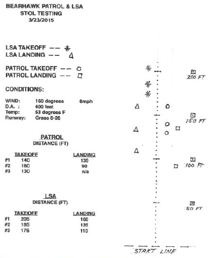
Patrol and LSA Takeoff and Landing Tests

Source: 2015 Q2 Beartracks, Bob Barrows
15q2nBob has been testing several different propellers on his Patrol and LSA prototypes. Here are the results of his favorites. For these tests the LSA was running a McCauley metal prop, and the Patrol was running a Hartzell Trailblazer prop. Mark Goldberg has just installed the same prop on his Bearhawk Patrol. Contact Mark to ask about special OEM pricing for orders through Bearhawk Aircraft.


15q2o
Continue reading

Rex Ervin’s New Bearhawk 4-Place

Source: 2015 Q2 Beartracks, Rex Ervin
15q2aArticles by Budd Davisson in the 2002-2003 era convinced me that the home-built Bear-hawk 4-place would be the right airplane to replace my 1964 Cessna 206. Since the kids were gone or soon to be, I bought a quick-build kit in September 2004. It was displayed at the Bearhawk booth at the Copperstate fly-in in October of that year on its way to Oregon. We flew down in the 206 and stayed at Budd’s B&B during the fly-in. Budd and Marlene were great hosts. The BH party there was a lot of fun!
I finished an extension to my shop in my hangar that fall and started construction in January 2005. I was working my full-time job in the first 5 years of construction. The second 5 years, during retirement, I had 3 back surgeries which slowed me down a lot. I finished construction in December 2014. I had a DAR inspection on January 2, 2015 and passed. I finished some minor details and had the first flight on March 9, 2015. I got busy flying the 40 hours off and had it completed with several 3 and 4 leg cross-country trips.15q2b
I used Stewart Systems covering and paint. I like the products. The covering was fun and very satisfying. The painting was difficult for me until I finally did it the way Dan and Doug Stewart tell you to do it, then it wasn’t that hard. I took the Stewarts covering/painting 3-day class before covering and painting. I had no other covering or painting experience. I have a Lycoming O-540 rebuilt by Bob with low compression pistons. He rates it at 240 HP. I love that engine! It is so smooth and powerful and has a very non-offensive, different sound for people on the ground. That may be attributed to the Larry Vetterman exhausts with mufflers for each side of the engine. The airplane flies so easily on low power, it is a joy to cruise around sight seeing throttled back and enjoy that wonderful panorama, looking over the nose so well and side to side. My wife loves to ride in the airplane due to the great view over the nose and the solid feel in flight.15q2c
For cruise I like 17-18 inches of manifold pressure and 2350 RPM. Leaned out at that setting, I get about 135 mph on 9.5 gph (6000-9000 feet msl). The engine, the prop, and I all seem happy at that setting. I also have a Bob tailwheel and gascolator. The tailwheel was an early model and had a bad shimmy. I replaced it with the latest model from Eric Newton. It has a shimmy dampener bolt to control drag and it works great. With no tension there was a minor shimmy. I tightened the bolt too much and had no shimmy but difficult steering. I loosened the bolt a bit and now have no shimmy and good steering.
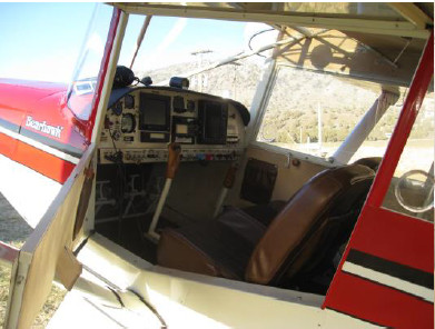
The airplane is set up for IFR, though I am not currently a proficient IFR pilot. I have a Trutrak EFIS with combined engine monitor, transponder, and PS Engineering EX100 Audio panel with intercom. The Micro Air Com is remotely mounted behind the panel, which also includes a GX60 Apollo Com/IFR GPS, VOR, ILS, Marker Beacons, and VAL INS429.15q2e
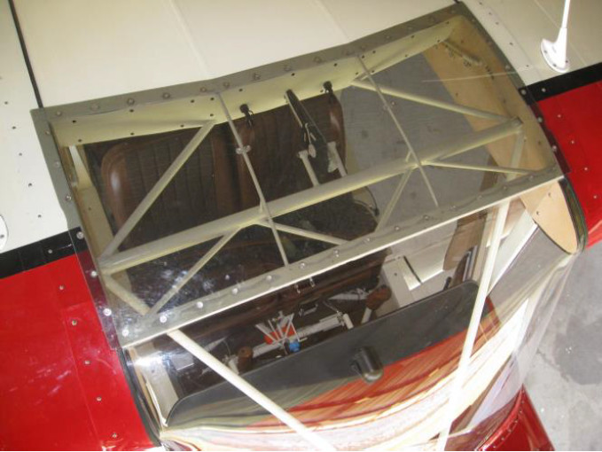
Custom items include a skylight, a sub panel for engine controls and switches, Stewart fiberglass wing tips, aluminum side panels, Kydex thermoplastic head-liner, flocking surface finish for side panels and headliner, glove box in panel, extended baggage compartment, and auxiliary fuel tanks.
I wanted to maintain the Bearhawk hump back and was able to do so with 1/8 inch Lexan, with minimal distortion of the skylight. The “break” in the shape of the rear portion probably helped with that.
I don’t know if the Stewart wingtips helped in any areas of performance. My Bearhawk is the only one I have ever flown. I am not one to spend a lot of time nailing down accurate numbers. Anything I report would have to be viewed with suspicion! I think the Stewart wingtips may improve low-Power cruise performance.
I really like the airplane, the handling and performance, visibility, cargo doors, and looks. Empty weight is 1547 pounds.
15q2f

15q2d

Dale Johansen’s First Flight!

Source: 2015 Q1 Beartracks
15q1vDale says: The first flight was in May, but I started construction of a new house in June. So only have 50 hours on it. It has a O540-E4B5. Local flying and one trip to Tucson and back. It has exceeded all of my expectations and will get a lot more use this spring and summer. Has very long legs with the aux tanks and the Oregon Aero seats make the long legs more comfortable than my old Aztec. My preferred cruise is 19/1900, which gave me an average 135 mph, according to the GPS, for the 2300 mi. round trip to Tucson at 9 gph.
Empty weight is 1545, but it has plenty of power to carry the leather seats, plexi skylight, constant speed prop and extra metal skins under all doors. The foam in the seats is quite heavy, but very comfortable on long trips. I only weigh 156, so make up some ground. Panel is all steam gauges with two gyros.
15q1w

2014 Q4 First Flights

Source: 2014 Q4 Beartracks
Congratulations to the owners of three new flying Bearhawks!
14q4nLynn Riggs says “My first flight was October 24th. Empty weight came in at 1590 pounds. I have an O-540 235hp engine in it. The only issue I have had with it is the worm gear for my flap system broke. I have 9.6 hours on it. The weather has not cooperated.”


14q4oBrad Lange in Australia, builder of plans 1076 writes “I have completed my testing and have received Phase 2 Certificate of Airworthiness. The aircraft flies really well and am having a great time with it.”


14q4pThe first Bearhawk Patrol to fly in South Africa is shown to the right. It has a stroker IO-370 with a 3 -blade MT Prop. The owner reported a trouble free first flight, saying that he was airborne before he had gotten to full throttle. It flew hands off and the owner is very happy. The plane (from a QB kit) was built by Wayne Giles, Bearhawk Aircraft distributor in South Africa.