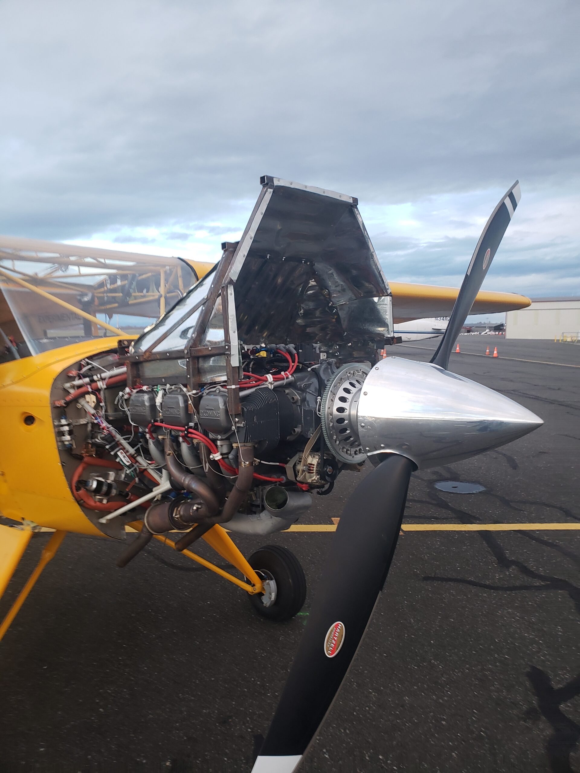
2026 Airventure Coverage – Summary


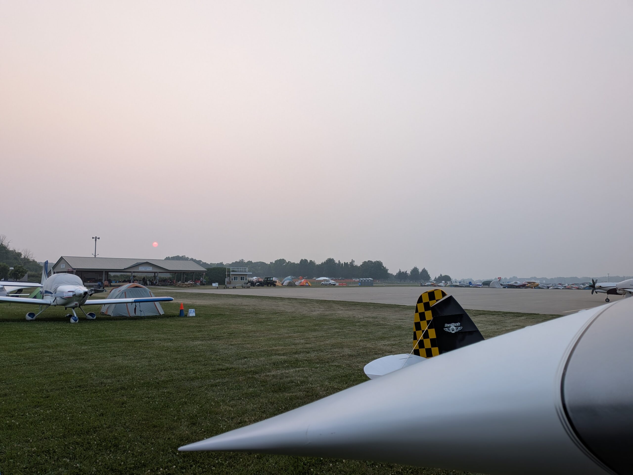
2026 was a great year at Airventure for Bearhawks. By my count there were at least 17 examples present. If the plane title below has a link, click there to see more detailed photos of that plane. Some have seen lots of previous coverage so I didn’t get detailed walkaround photos of those. At times the sky was full of wildfire smoke and that made for some interesting photography lighting.

Bearhawk Patrol – N37BP – Red and White – Carlo Cilliers – “Plans Champion!”:

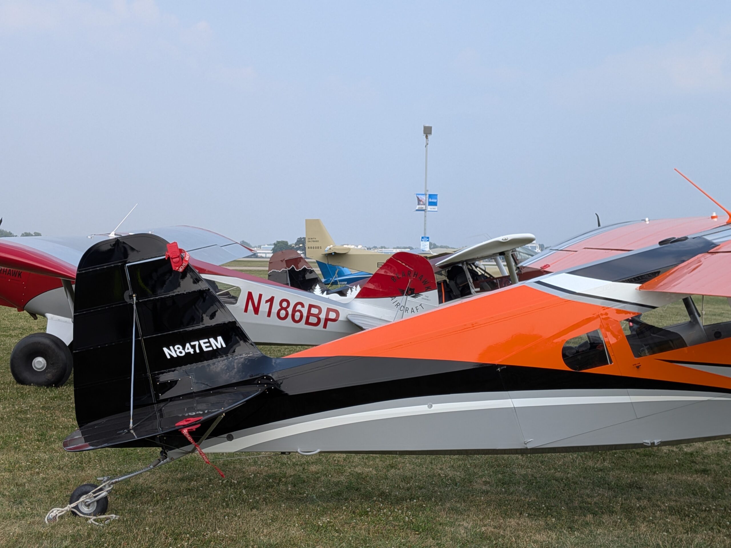
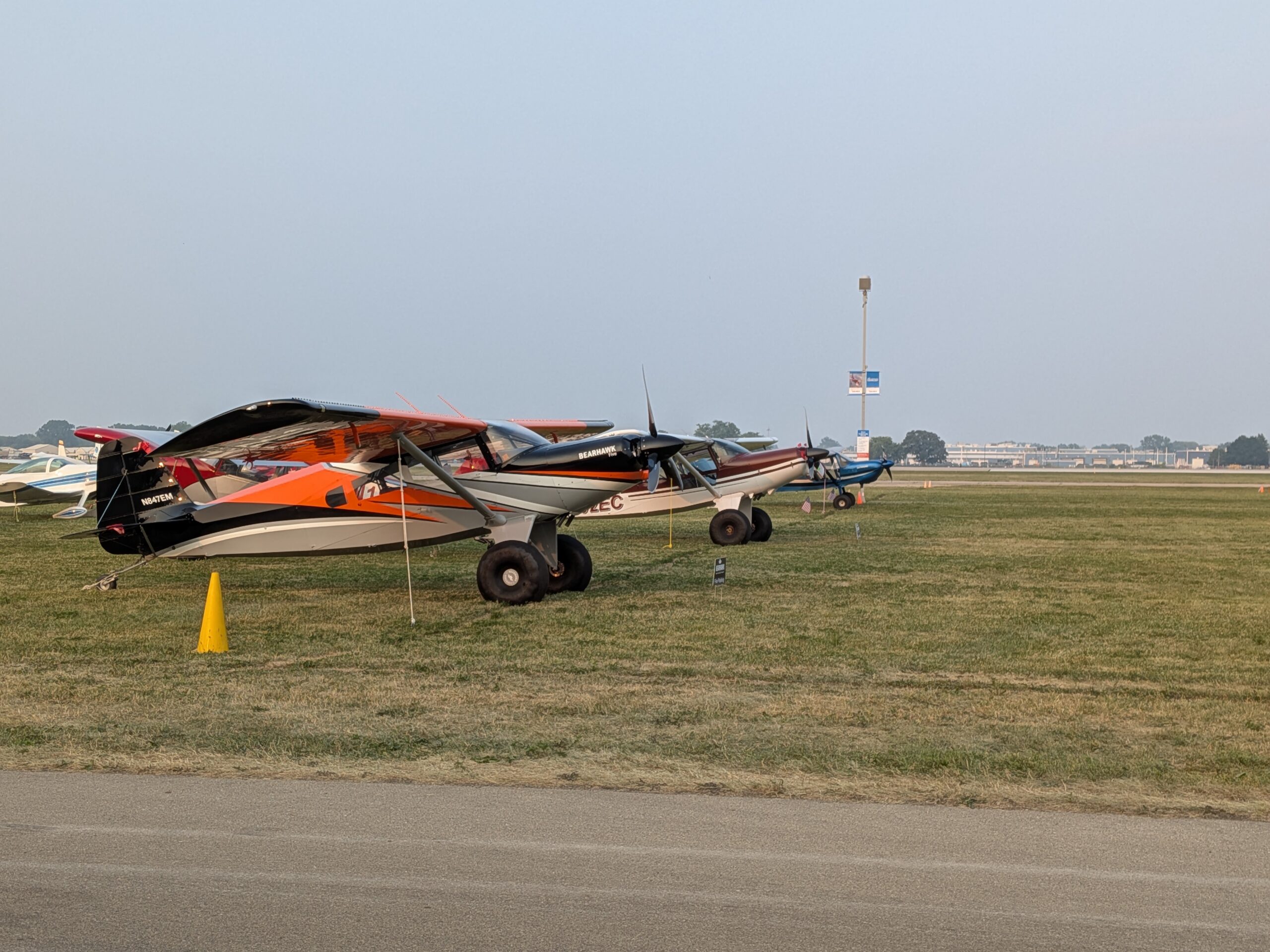
Bearhawk Five – N847EM – Orange, Black, White, Gray – Elliot and Melanie Abel – “Kit Champion!”:

Bearhawk Five – N812MN – Yellow and Black, in the Kit Booth:

Bearhawk Five – N902EC – Maroon, Black, and Red, with a mountain scheme – Chris Cummings:

Bearhawk Five – N605PS – Metalic Blue and Silver – Dennis Ramsey:

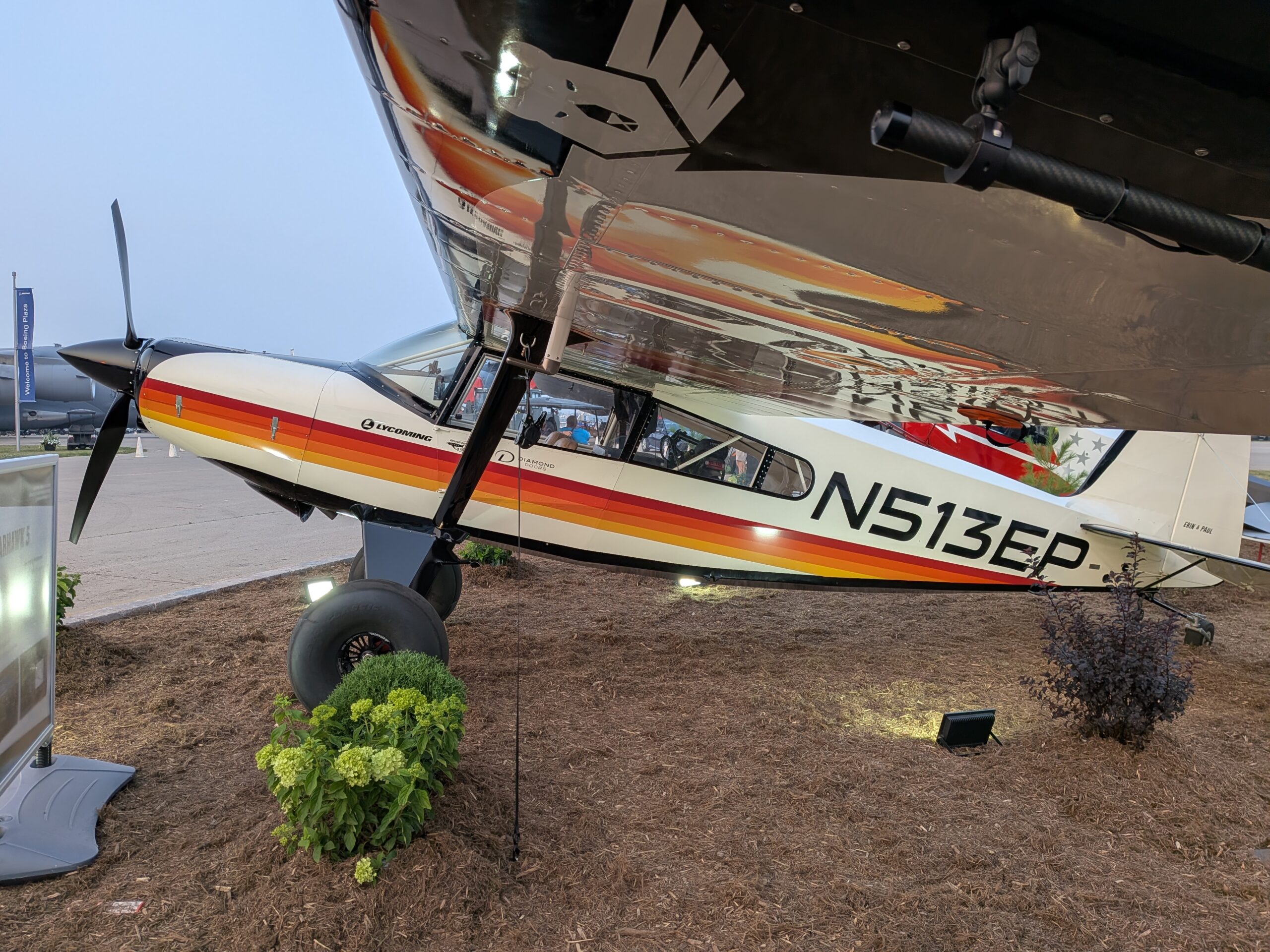
Bearhawk Five – N513EP – Erin and Paul, in the Garmin Booth:

Bearhawk 4-Place – N789WM – White and Silver – Stephen Ingram:

Bearhawk 4-Place – N303AP – Red and White – Jared Yates:

Bearhawk 4-Place – C-GSOI – Blue and White, Maple Leaf – George Huntington:

Bearhawk Companion – N236WZ – Purple, Orange, Green, and Silver – Stol It:

Bearhawk Patrol – N96NH – Green, Cream, and Gold, Hydraulic Float Attachment Provisions – John Meade:

Bearhawk Patrol – N186BP – Red and Silver – Bearhawk Aircraft:

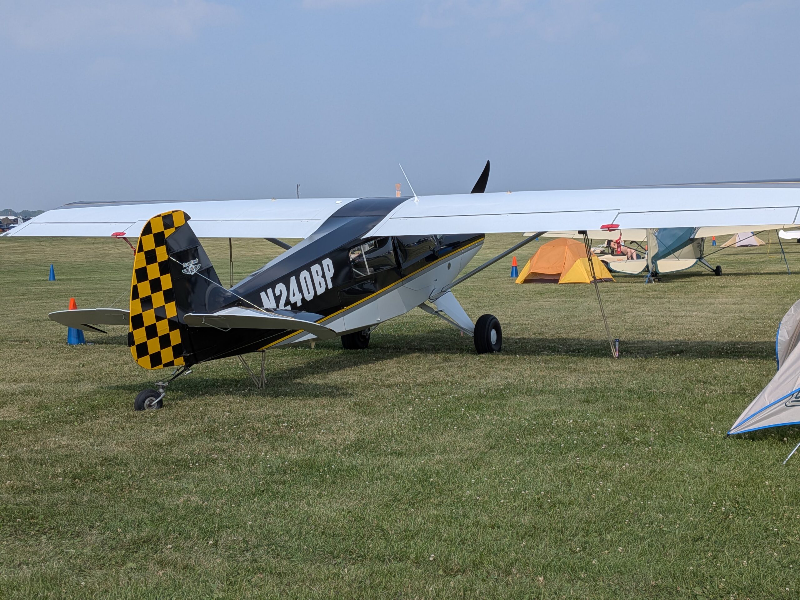
Bearhawk Patrol – N240BP – Black, Yellow, and White – Dennis Reynolds:

Bearhawk Patrol – N241BP – Yellow and White – Donna Svoboda:

Bearhawk Patrol – N62588 – White and Gray – Brooks Cone:

Bearhawk Patrol – N584P – Maroon with Mountains – Jeff and Lynne Stoltenberg:

Bearhawk Patrol – N169PL – Amphibious Floats – James Crane:

Brooks Cone organized a Bearhawk Walk on the Tuesday of the show. Here is more detail about the walk.

Later that evening, Bearhawk Aircraft hosted a catered BBQ dinner and shared some updates about happenings at the kit factory and build assit.


Bearhawk LSA builder Wayne Powell noticed that an AN bolt manufacturer had a tent set up displaying a nice alternative to cadmium plating, using zinc and nickel. They had lots of good things to say about this plating’s durability and corrosion protection, and it is also much more environmentally friendly than cadmium.

I had a nice visit with Donna and Dennis to hear about their corresponding Bearhawk Patrols. Donna especially was motivated to reach 1000 hours before arriving at Airventure, so that she could display the propeller card that says “This homebuilt has flown over 1000 hours”. While she was crossing the mountains on the way to the show, she saw the hour meter getting close, and even got a video of the crossover from 999.9 to 1000.0. Dennis reached the same milestone a few hours later. They are no doubt some of the most experienced Patrol pilots in the world. Last year they were talking about having trouble finding an overhauler for their Whirlwind props. That has been sorted out, and Donna was able to find replacement spinner for her plane, despite the Whirlwind supply chain becoming quite constrained. They both installed plenums under the cowlings to promote cooling efficiency. In Donna’s plane, this led to an unexpected side-effect. With the pressure being reduced on the cowl itself, she found that the piano hinge at the upper cowl door was no longer being held in place. It started creeping forward, towards her newly-overhauled beautiful composite prop. She could see this creeping happening, and also could see the cowl beginning to separate where the pin was no longer in place. She decided to make a precautionary landing to sort it out, and everything turned out ok. Be sure to think about securing this hinge pin, especially if you run a plenum.

There were not any Bearhawk LSAs at the show that I could find.

Here were a few more photos:

These wheels and brakes are being designed by Acme Aero:

The Erin and Paul Bearhawk Five has some special cabinetry that includes a little kitchen. Sorry for not having better photos, but I’m sure they have a video about it.

Stephen Ingram’s Bearhawk 4-Place N789WM First Flight in Texas

Source: 2025 Q3 Beartracks
N789WM first flew on August 5th, 2025. You can read about my experience with the first flight of my newly built Bearhawk aircraft, following my transition training in North Carolina, on the Bearhawk Forums. In summary, despite careful preparation, the initial attempt was aborted due to a fouled spark plug, and the actual first flight revealed a misconfigured RPM sensor, leading to false high-RPM readings and considerable anxiety mid-flight. Minor issues like a lost fuel cap and unfastened tailwheel chains were discovered post-flight, reinforcing the importance of a thorough punch list and better planning. Ultimately, the flight was successful and educational, and shows the value of preparation, clear checklists, and learning from unexpected scenarios.
Since that first flight, there has been ongoing maintenance, discovery, and tweaking. After the first couple of hours, I was struggling to keep my cylinder temperatures within a reasonable range, and having to level off and build speed to keep the rear cylinders below 430F. I was very concerned about glazing before the rings had a chance to seat on the brand new engine. After having a friend look over my engine, and baffles, we realized a couple things: My front air dams seemed too high in his experience; and I hadn’t ever really gotten back around to sealing all the holes in the baffling. He also has a O-540, but in an RV, and he said he ended up without air dams at all. He reasoned that if my temps are high, I could remove the air dams altogether and the worst case they are too low and I have to put some back. I agreed, and drilled off the front air dams.
Next, I set about diligently and thoroughly finding every crack of light shining through the baffles and sealing it with RTV. I prefer the gray RTV, as the color blends in well with the rest of my engine. This ended up using almost an entire tube of RTV. But I felt confident that this would help address the heat issue. The main is to get that pressure differential between the upper and lower engine great enough to pull air though the cylinder fins, and it doesn’t take much, but any hole in the baffling is lost opportunity to carry away heat, and pressurizes the lower cowl.
The next flight the CHT’s were much better, and increased much more slowly. Success! But now, the next problem…my oil cooler is front mounted with a scat hose leading to a duct over the cooler to put the air through it. Lots of gaps around the fiberglass duct against the face of the oil cooler. Get another tube of RTV…
I also struggled with high CHT’s around #5, and a common solution for this, depending on how your cylinders are cast, is to build an air duct to shunt air around the backside of the cylinder. This called for breaking out the rivet gun and some scrap aluminum and within a few hours I had a decent looking duct. This greatly helped even out the CHT on #5 to something close to the other cylinders.
My project was a stalled out project with a new engine that had been sitting for a number of years. I had borescoped the internals of the engine as much as possible, and it all looked pristine. However, in the last few hours, I have had a number of seals, O-rings and gaskets start to leak. If you have had your engine for a while, the internals are probably fine, but you should expect to go through a round of fly, find the leak, replace, fly, repeat etc. Many rubber and non-metal parts of an engine wear out over the years whether they fly 1 hour or a 1000 hours. This lead me to have a number of oil leaks, an intake leak, and a fuel leak, all within the last 10 hours. Nothing catastrophic, but annoying nonetheless.
Initially, my flight controls felt very “heavy” and the adverse yaw was over the top. Thanks to the forums, and some posts I found there, I decided to go back through my tail and take it completely apart and identify any source of friction. I found quite a few places that I could have done better the first time, and most of my friction was actually in the trim tab on the left side. The hinge would bind against the paint and the clevis pin was tight in the hinge. I sanded, reamed, polished and straightened the elevators relative to each other very carefully, and this removed almost all the friction in the pitch.
For the adverse yaw, I decided to check my aileron rigging again, and raised both ailerons about 3/8 inch reflexed, as many had reported this removed a lot of the adverse yaw. I also went back through my flap rigging and made sure they were exactly equal to the wing trailing edge, and got everything as straight as possible.
The first test flight after the rigging changes was noticeably better. Most of the adverse yaw was gone, but enough to still keep you on your toes, rudder-wise in the turns that is. My autopilot no longer complained about trimming while maintaining altitude much better. I still have a very slight right roll that I am hoping a little more attention to the rigging will alleviate, but if not, I will employ the “washer trick” under the heavy wing hinge.
I am thankful that we live in the experimental side of aviation, since it allows us to experiment and to have “experimental” avionics and tools to discover and address issues quickly and confidently. Without a good engine monitor, I would not have been able to tell exactly which spark plug had fouled on my first flight. Without continuous monitoring, I would not have realized that one of my CHT problems was a leaking intake gasket. I also want to emphasize how invaluable sites like the Bearhawk Forums, Savvy Aviation, and Flysto are if you are willing to share your engine and flight data. Using Savvy, I was able to analyze engine data and dial in on the intake leak. Using Flysto, I was easily able to identify pitot-static errors, and rewatch and critique my flying. And of course the Bearhawk forums are great for tips, tricks, and the comradery surrounding this excellent airplane type.
As of the evening I am writing this, I am at 17 hours, having a wonderful time flying, looking forward to seeing other Bearhawkers out there, and just found another oil leak.

First Condition Inspection Status Update – Crankshaft Seal Leak and Battery Overheat Mitigation

Source: 2025Q2 Beartracks, Paul Minelga
Last month I did my first condition inspection. It’s hard to believe it has been a year since I got my Airworthiness Certificate! As the months went by, I kept a running squawk list of items that needed attention, but weren’t safety of flight items. In addition to all the inspection items normally done on an “annual”, I took care of the items on the list and did a deep dive into the entire aircraft, from one wing tip to the other, nose to tail. I even cut open the EFII boost pump fuel filter (FF-2 Pre-filter) to see if there was anything in there as it’s a sealed unit. I found nothing inside, completely clean except for a tiny fleck or two. It was $48 for a replacement, but now at least I know what it looks like on the inside.
One thing that was a bit of a concern to me was the nose of the engine always seemed like it was just a bit wet. Nothing that I would consider a leak, but a tiny bit oil was coming from somewhere. I was doing the inspection in the hangar I did the initial assembly in. The mechanic that helped me along the way through the years suggested that I pull the prop to have a look at the nose seal around the crankshaft. He called it the “Lycoming runny nose”, as from his experience they are susceptible to weeping from that crankshaft seal. But, with only about 43 hours on the engine it shouldn’t be wet up there. At the time he was painting a customer’s aircraft wings and had time in-between coats to lend a hand, so we pulled the prop. The seal was intact. But, he could place a pick that had a 90 deg bend at the tip onto the seal and rotate within the bore! It was pretty unusual as the bore the seal rests in needs a sealant applied before the rubber seal is pushed into place. We were sure that we had done this on assembly, but the evidence suggests otherwise! The old seal was removed, bore was thoroughly cleaned, sealant applied and a new seal was pushed into place. After the post-inspection run-up we had a good look at the nose, and the dry case proved we had found the culprit.
I did install a K&P S15 permanent oil filter in place of the normal Tempest oil filter. I’ll report on that and how it works out in the future.
One embarrassing find was the elevator trim cable turnbuckles weren’t safety wired! On my BH they are inside the back of the fuselage, in front of the horizontal stab. I don’t even know how many people looked the airplane over in the previous 12 months and everyone had missed it. I’m not proud of the find, but I’m glad it was found and taken care of. I pride myself on being anal-retentive on such things, but such a simple thing being overlooked is pretty scary. Anyway, lesson learned and I hope as others look at their builds when they are getting ready to fly to triple-check everything.
Another discovery was the bottom of my EarthX ETX900 battery case had melted! I never had any issue with the battery and it performed great. I shared these pictures with EarthX tech support, along with pictures of my installation. They said it was probably too hot against the firewall and that caused the case plastic to sag where it wasn’t supported. They said to send it back and they would check it out. I did, and after evaluation they said the battery checked out fine. They would put the components in a new case and send it back. I got it back and it looked suspiciously like a new battery, at no charge! It does get hot at the firewall and I do remember when I was breaking in the engine, it ran pretty hot under the cowl. On one day last summer, after refueling on one of the engine break-in flights, I did get a battery temp warning light indication. That may have been the time when it happened, I don’t know. But it wasn’t easy to spot and the folks at EarthX were amazing to deal with. At their suggestion I fabricated a heat shield box for it, covered with Thermo-Tec 13575 aluminized heat barrier. I’ll fly with it for a bit and see what happens and determine if it is effective in preventing any thermal deformation of the battery case. If it isn’t enough. I’ll probably install a blast tube for extra cooling.
The last thing I did was install an AV-MAG magnetometer in the right wingtip for my AV-30s. The headings on both units are worthless without it. The installation went relatively well, but it took some doing. We had to use the wiring for the nav light to pull the magnetometer shielded wire and some lacing tape through the wing, and then used the lacing tape to pull the nav light wire back through. Moral of the story, maybe when the wing is open, leave a string or something in the wire path to help someone thread something through in the future. After the installation, I had to go out to the compass rose and calibrate both units at 30 degree increments. Since there were no lines connecting the painted compass arrows, it was impossible to get it accurately on centerline. I ran to the local hardware store and got some lime green paracord. I used a couple of heavy things to hold each end in place on the painted compass rose while I wrestled the BH into position. It was a royal PITA to do by myself. The wind was blowing and it was cold, but I did get it done.
If you are building, don’t give in, don’t give up. It’s worth it!

Fuel Pumps and Flow Testing for Big Engines with Carburetors

Big Carb Engines, Fuel Pumps, and Flow Testing, part 1
Source: 2025 Q1 Beartracks, Jared Yates
Back in early January I was departing for a short flight back home, when I got a fuel pressure warning on the takeoff roll. The EMS is configured to alert when the pressure drops below 3 or so PSI, because I have found that if I forget to turn on the boost pump, that’s about what it drops to at very high power settings. Usually the alert reminds me to reach down and turn on the boost pump, but this time, the switch was already on. When I got home, it didn’t take much testing to find that the little electric Facet cube pump had decided to retire.
This seemed like an easy thing to fix, the only question was whether I’d have to order a replacement or whether I might get lucky and find one at a local parts store. Little did I know, I was about to step into a rabbit hole that three months later I’m still not quite out of.
Our plane has a carbureted O-540, and larger carbureted engines are the only ones that share this problem. For folks with a carbureted 360, including ourselves when we had one, 3/8” fuel lines are perfect. They can provide around 30-35 gph, which is 150% of the required flow rate of the less-thirsty engine. For folks with a fuel injected engine, you’ll be using higher pressure pumps anyway, so the 3/8” lines are plenty sufficient, and this rabbit hole is moot. Some builders have been able to reach acceptable flow rates with 3/8” systems and big carbureted engines, especially if they don’t use a fuel flow measuring sensor, though I was not. Also, I really prefer to have a fuel flow indication for several reasons. It’s a great real-time diagnostic, it helps with establishing throttle/prop/mixture settings for various phases of flight, and helps with flight plan monitoring. An electronic system can keep track of how much fuel has passed through the sensor and provide an indirect fuel quantity indication and warnings. But the fuel flow sensors are all designed with tiny little passages, that make for a big flow reduction– much more on that later.
When we first acquired our current plane, it had an engine-driven diaphragm pump and the electric boost pump, which is a Facet 40108. I did a flow test to see if we could remove the pumps, but did not have anywhere close to sufficient flow with the fuel flow sensor in place, so I carried on with the pumps in the plan. The 40108 pump is handy because it has 37-degree flared fittings integrated into the inlet and outlet. The internal passages are the same size as the 3/8 lines, and it has no additional check valve or positive flow shutoff when power is removed. When I went to purchase a replacement, I found out that the 40108 pump had been discontinued. This shouldn’t be a problem, Facet has a whole line of pumps. Unfortunately, almost all of the cube pumps have 1/8” pipe thread fittings. That’s not going to work. The Vans builders have changed to the 40135, which has the right fuel pressure for a carb (nominally 5-7 PSI), but uses the 1/8” passages. It does not have a check valve per the specifications chart, though all of these pumps do have a natural check valve function and prevent reverse flow. There is a 40109 which has 3/8 pipe thread ports, but it has an extra effective check valve function. I ordered a 40135 and a 40109, and holding them on the bench, I could tell that the 40109 was not going to work. The check valve provided so much restriction to forward flow that I don’t think the gravity pressure was going to open the valve at all. The 40135’s natural check valve function was a little more stiff than my old 40108, which is 20 years older, but tolerable. The problem was just the tiny ports.

So if we were going to continue to use pumps, we had a few options. One would be to run multiple 40135 pumps in parallel. I considered one on each 3/8” line just upstream of the fuel valve, but there would be some serious drawbacks. Basically there would be no cross-flow capability between the left and right tanks, because the pumps are natural check valves. We could run two pumps side by side with Y or T fittings, in hopes that the flow rate between the two would be sufficient with the electric pumps off. I wasn’t confident that this was achievable, but also didn’t test it. Another option was to attempt to modify the pump, such as drilling and tapping new threads to increase the inlet and outlet size, or maybe destroying the check valve function of the 40109. I wasn’t confident that either of these would be successful, and even if they were, replacing the next broken pump would require repeating the mods.
The next option was to consider a fuel system redesign that would allow us to eliminate all of the pumps. I spoke with Tyler Williams about his installation, which is a carbureted engine bigger than ours, with no pumps. He found that by increasing the line size to 1/2” from the fuel valve to the carb, he was able to get sufficient flow without any pumps, though he was not using a fuel flow sensor. It makes sense– using 3/8” lines for single tanks, but 1/2” once they are combined. This was the most appealing option, but sometimes even a small change ends up big.
The first order of business was the fuel valve. Our plane was built before the Newton SPRL valve was available, so it had an Andair valve. There have been a few iterations of the Newton valve, and it is better now than ever before. The current version is actually Bearhawk-specific and is only available from Bearhawk Aircraft. It is manufactured so that the outlet is on the aft end of the valve, so that the fuel can flow aft/downhill to the gascolator. The SPRL valve has its own non-standard interchangeable fittings, with several different options available. Bearhawks with 3/8” systems can use Bob’s gascolator, which has 1/4” NPT threaded ports. The valve can be configured with 3/8 inlets for each tank, and a male threaded 1/4 NPT outlet which can be directly attached to the gascolator. This saves fittings and makes for a very clean installation. In our case we set aside the 1/4” fitting and ordered a 1/2” flared fitting, which is part number 05-04453 at Aircraft Spruce, for a pack of 3. Now all we had to do was defuel the plane, remake the two lines that bring the fuel to the valve (because the old lines were an inch too short) and redo the mounting of the valve to the floorboard. Glad I didn’t have any other plans for January?
We also needed to up-size the gascolator. The only viable option that I could find was from Steve’s Gascolator. They make two units with 3/8” NPT ports, and two different bowls. Height is important in the Bearhawk, because we are trying to fit the gascolator between the floor and the belly. The shortest combination from Steve’s was the SA3-10-B, which has a 3-ounce bowl. I used one AN822-8D fitting on the inlet side. This fitting has 3/8” pipe threads on one side and 1/2” flare on the other side of a 90-degree elbow. On the outlet side I eventually used the AN823-8D, which is a 45-degree version, because it did a better job of pointing the line where it needed to eventually get. If you are following along and ordering parts, the gascolator also requires a 1/8” pipe thread plug at the top. I used an aluminum Aeroquip FCM3685 though I did carefully file it down to be almost flush with the top of the gascolator housing, so that the gascolator could sit as high as possible. I made a u-shaped bracket out of aluminum left over from the instrument panel, which attaches to the floorboard with 3/16 rivets.
Going forward to the firewall, I increased the size of the existing AN837 bulkhead fitting to the –8, and that also needed one AN924-8 nut. These larger fittings are much more expensive, I’m noticing. Then I’d also need a 1/2” flexible line to go from the firewall to the carb, and a new fitting for the carb itself. The carb has 1/4” pipe threads, so something like an AN822 would be nice, except that MS20822 doesn’t list a fitting that has a 1/2” flare fitting and a 1/4” pipe thread. I found one at Pegasus Auto Racing, part number 3253-04-08. This fitting is aluminum, and I would prefer steel, but the carb itself is aluminum so I was willing to compromise. A 45 or even straight adapter could also work here, depending on how your line is routed. I have found that using a 45-degree fitting at the firewall and approaching the carb parallel to the thrust line helps keep the flex line from rubbing on the cowl and clear of the exhaust, but there are any number of good ways to get this done.
I didn’t have the where-with-all to figure all of this out with a single order. A few weeks and around $1000 into this project, what was there to show for it? I’m glad you asked. First, let’s talk about the flow rates, which means talking about flow testing. In the US, testing is not required by regulation. It used to be required for store-bought planes but it seems that requirement became less specific in recent years. Canadian builders tell me that the flow test is regulatory for their homebuilts. I decided that the test was important enough to comply with. I wanted to get 150% of the engine’s maximum flow rate. Past flight experience with this engine and prop tell me that I’d like to see 37gph in the test, in order to remove the pumps. With the new lines, and no fuel flow sensor, I ran some preliminary flow tests with the wheels all on the ground. (A proper test would come later, with the main wheels elevated.) I was getting 47 gallons per hour on Both. This is great! But then, I installed my old Flowscan fuel flow sensor in the flex line close to the carb, and the rate dropped to 32 GPH. This was not great. I had ordered an EI FT-90 Gold Cube sensor to try, and it increased the flow to 34 GPH, meaning there was still some work to do. Tune in next quarter for part two, getting to a successful fuel flow measurement.

Bearhawk Patrol N62588 First Flight

Source: 2025 Q1 Beartracks, Brooks Cone
I wrote an article last issue on a Patrol that I started in 2017 and am nearing completion on. I talked about the theme of efficiency, utility, reliability and maintainability that drove decision making of the build. At that time the FAA paperwork had been submitted for its airworthiness inspection.
I signed off the condition inspection on January 2nd, the FAA performed the airworthiness Inspection on January 21st and the first flight was on February 22nd. The Patrol has about 7 flight and 10 hours on her now as of this writing.
I knew that the FAA’s inspection of my Patrol would be broad in nature rather than detail oriented. I wanted and needed an inspection with detail, so I hired an A&P with IA in November to inspect it. The inspection lasted about 3.5 hours. With a mirror and flashlight in hand he looked at everything and wrote discrepancies down on a tablet. I studied what he did and how he “thought” as he looked around. At the end of it I had 75 items to fix, a builder tutorial of how to inspect, and a higher standard to rise up to. That was just what I, an untrained amateur who builds alone at home, needed. In the subsequent weeks as I worked on his list, I kept discovering my own items and so the number of items to fix nearly doubled. I am convinced I would not have appreciated a judgmental eye on my build if a DAR inspection
was combined with an evaluation for an airworthiness certificate. I suppose the way I had it done gave me a measure of protection from failure and confidence in more than just “passing”.
The first flight was done on Saturday morning, February 22nd. The temperature was 17F and it lasted about 40 minutes with the objective to run the engine hard for break-in. I’ve got good cabin heat, low CHT’s and very good oil temp control. My oil system has a shutoff valve to the cooler controlled in the cockpit. I have outstanding control of oil temp. The break-in schedule after the first flight was interrupted by my ADS-B performance report saying it’s inoperative.
My Patrol resides in mandatory ADS-B airspace, and so flights #2 and #3 were dedicated to making it operational. Break-in continued on Flights #4-7, providing 9 more hours on the engine.
When we break-in an engine the question we all ask is “Will it run too hot?” My CHT’s were normal from the first takeoff. With 65% confidence I say CHT’s were not hot because of time and care spent on crafting two firewall forward items – Sealing the baffling, and the design of the cowl exit.
Air that enters the top cowl is for engine & oil cooling. Air that leaks and dodges any cooling fins is wasted drag and reduces the pressure differential across the cooling fins, so I decided to plug them all up. A flash light in a dark hanger strategically positioned below the cylinders reveals all the leaks. Most of them are found around the base of cylinders. I have a friend at the airport. His name is Wayne. Wayne is a super inquisitive, and enthusiastic builder who is at the airport every day . I’m just kind of average but am further along so we help each other out. Life is better when humans collaborate. Occasionally Wayne uses good words that describe a situation. Three that come to mind are “Rat Hole”, “Sticktion” and “MVP”. Sticktion is the sticky friction we overcome when we initiate movement. After things get going, the stickiness of high resistance is reduced. MVP describes a part or assembly that is Minimally Viable…a Minimally Viable Product. An MVP is not pretty but gets the job done and keeps the build moving along. We’ll make it pretty later on.
Now about rat holes. Cars have rat holes and manufacturers don’t like them. My grandma’s basement fruit cellar had them. The average Lycoming baffling installation has rat & mice holes too. They are found in places like corners, at the cylinder base and inner cylinder baffle. Lots of air passes through them without cooling. When a rat hole is plugged, the cooling improves and drag is reduced. So I search out and seal up baffle joints and small stuff with ahigh temp silicone product called Permatex Ultra Black gasket maker. I think the black Permatex looks better than the red stuff but that works too. Some spots are difficult to reach, so I fill a small syringe with Permatex. A 12” piece of tubing pressed onto the syringe nozzle helps apply it there. Another tool I used was a tongue depressor.
My flashlight easily exposed four rat holes the size of my thumb. They got a piece of fiberglass impregnated with Permatex. I place plastic sheathing onto the top of my workbench, then put down a small piece of fiberglass cloth. I squirt some sealant onto the cloth then fold the top of the plastic over it so the sealant and cloth are sandwiched by the plastic. Then I press the sealant into the weave with a putty knife. It should be mess free. When the cloth is fully impregnated with sealant, I cut the patch to final size with scissors, remove the plastic and plug the rat hole by stuffing it with hemostats.
In conclusion, my Patrol is flying, I’m breaking in the engine, and have cool temperatures that I think is due to tight baffling, and the engine cowl design. Next quarter I’ll share how I incorporated the tunnel and cowl exit, and share with you how my engine break-in went.

A Few Walk-Around Details of Jay Townsend’s Bearhawk Companion, Nearing its First Flight

Source: 2024 Q4 Beartracks
On the boot cowl Jay used a nifty carbon fiber NACA scoop made by Bonehead Composites. The paint is flattened to more closely match the texture of the Oratex covering. The covering is translucent, so poking my head into the tail cone felt like being under the sea. The black box on the left side of the photo (right side of the fuselage) is a tube for longer cargo items like fishing poles. The engine sump includes a heater plug sold by Anti-Splat Aero.

Jay has installed Hall Brothers vortex generators, based on testing from Patrol builder Chris Spira. They are 7.25 inches forward of the main spar rivet line, spaced laterally as the skin overlaps allowed.

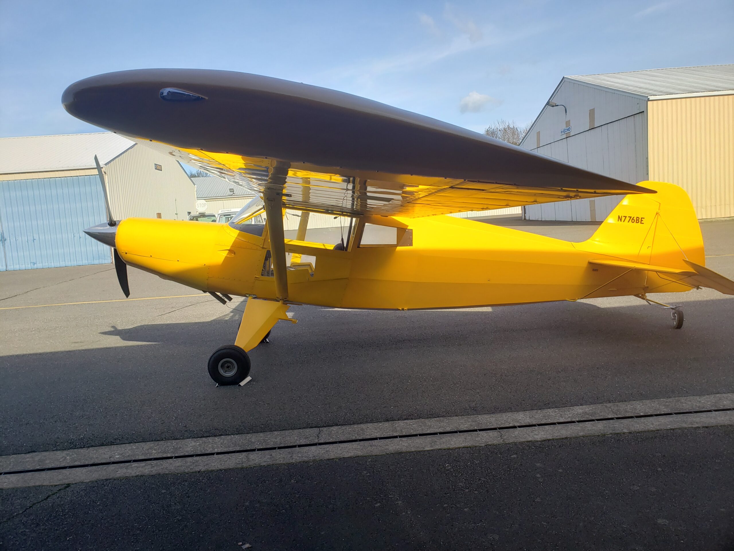
Bearhawk 4-Place N776BE First Flight in Washington

Source: 2024 Q4 Beartracks, John Reddick
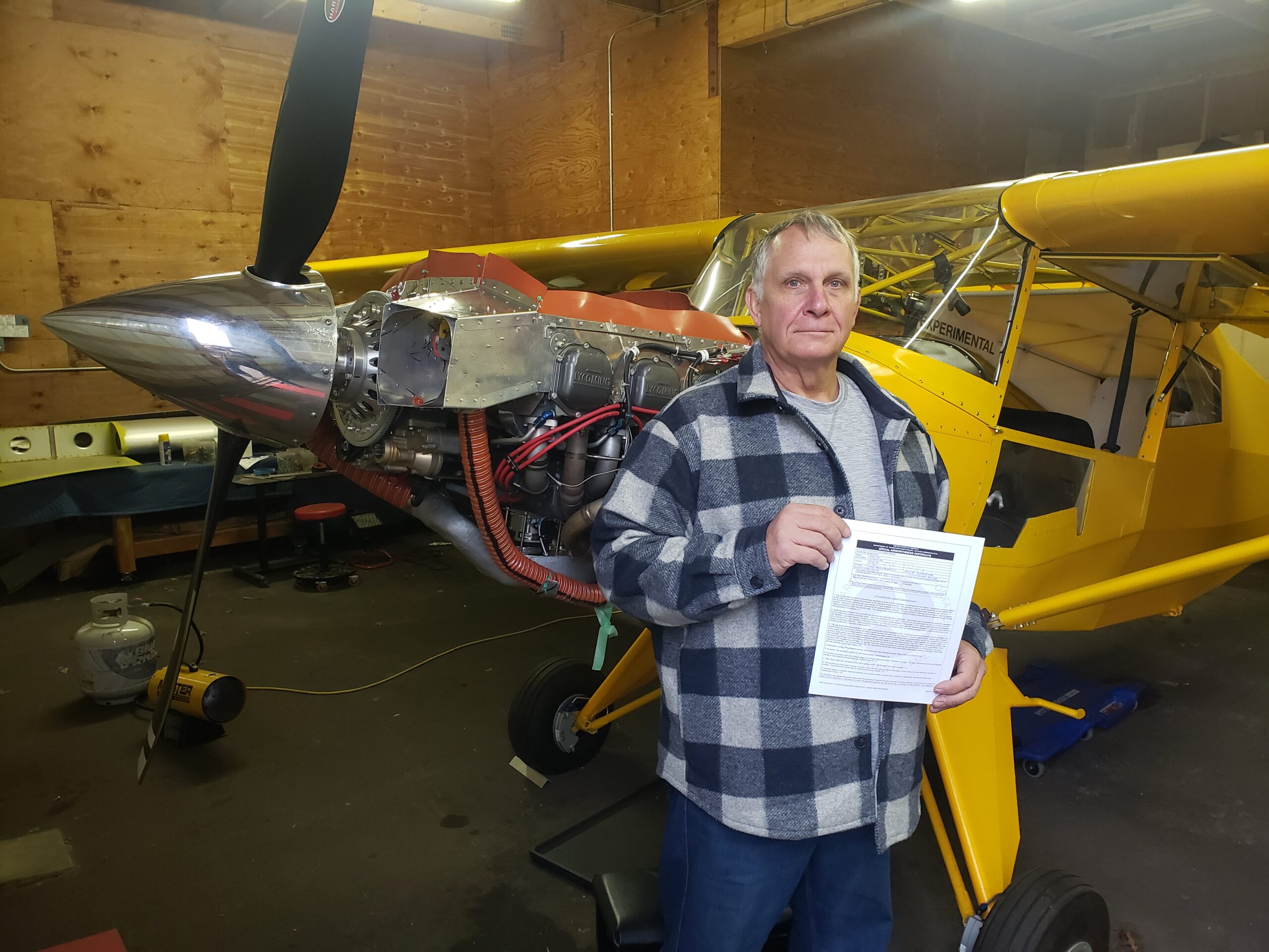
N776BE flew for the first time on Dec 6, 2024 after 6 1/2 years of on-and-off building. I actually only worked on it for 2 years and 4 months. I did numerous “off the ranch” things to the QB “B” model kit. All of that contributed to the extended build time. It was inspected by a DAR on October 30th, 2024.
I have about 5 hours flight time in 4 flights, most things working well. Sorting out a heavy left wing, and noise on the VHF com. The #6 cylinder gets hot pretty quick on climb out, despite it being 40-45 F outside. Other cylinders are fine in climb, and all are fine in cruise. Probably mislocated oil cooler flange (installer error). Other than that, going smoothly.
I think the two things that made the first flights much less stressful were 3.2 hours of transition training with Jared, and running the engine in on the ground for 2 hours (picture below). Both gave me a lot more confidence on the first flight.
My “off the ranch” mods were:
-Custom fold down instrument panel
-Composite tail fairing
-Electrical system
-SDS EFI/EI
-“Almost” 2 alternators
-“Almost” 2 batteries
The panel is a simple, single EFIS with a tablet, single com, and remote transponder. The EFI/EI turned a simple plane into a bit of a high school science project, wiring-wise. But I am most comfortable with EFI, and have done a huge amount of 12V wiring, including a business I had for 3 years. This may not be the best choice for someone who hates wiring.
I also used Oratex (which caused the composite tail fairing). If it lasts a long time I love it but it was tedious and time consuming to install.
Empty weight was 1403, CG was 7.1 inches (67 lbs on the tail). IO-540, 2 blade Trailblazer, full skylight. That weight is on small tires, and no back seat. That makes it the mid 1400’s with bigger tires and a back seat. I need 50 pounds of ballast with only front seat occupants.
It is exactly what I wanted when I ordered the kit. Like a lot of homebuilders, I always wanted to build an airplane. I even bought a set of plans when I was 15 or 16. I ended up flying for a living, and moved around so much I was never able to build one, until now.
Thanks to everyone on the forum for all the contributions. I knew what I was getting into before I bought the kit. Thanks to Jared for moderating a great forum, and Mark and Bob for the customer support.
I will put up some posts on my “off the ranch” stuff if anyone is interested.

A Corvair Engine for the Bearhawk LSA

Source: 2024 Q1 Beartracks, David Swartzendruber
I am building a Bearhawk LSA and one of the engine options for the LSA is a Corvair auto engine conversion. This is what I have chosen for my LSA and I completed my engine build at the end of 2023 during a 3-day supervised build in William Wynne’s shop in Florida. Bob Barrows and William Wynne worked together to design a motor mount for the Corvair engine in the Bearhawk LSA and this mount is available from William. But I’ll back up and start at the beginning of my story.
Like many of you, I decided I wanted to build an airplane many years ago, about 33 years ago for me. However, along the way I lost that dream when it didn’t seem like time or money would allow that to happen. About five years ago, that dream was rekindled when I picked up an unfinished non-Bearhawk project for a very affordable price that was designed to use a VW engine conversion. As I thought about what to do for an engine, I came across the Corvair and William Wynne’s website, Flycorvair.net, and began to consider using a Corvair engine in that project. Through the information on Flycorvair.net, I also discovered the Bearhawk LSA was a good candidate for the Corvair engine and I became less enthusiastic about the project I had acquired. I eventually decided to order a Bearhawk LSA kit and sell the other project.
Having already started down the path of building a Corvair flight engine, I thought I would go ahead and complete that while I waited for my LSA kit to arrive. The first step is to get a conversion manual from William Wynne. This manual includes information about which core engines can be used to build a flight engine. I picked up a 1965 Corvair parts car for $250 and the engine from that car became my core. Corvair flight engines always start with a 1964-1969 engine because engines earlier than that had a smaller stroke, lower displacement and lower strength crank and rods. My core engine was locked up, but I was still able to disassemble it and discovered that the piston rings on one piston had rusted to the cylinder wall. To my surprise, I found that my 1965 engine had a crankshaft and rods from a 1963 or earlier engine. This ended up not making any difference because I decided to go all out and build the bored and stroked version that bumps the displacement up from 164ci to 200ci, also referred to as the 3.3L. The 3.3L engine requires a new billet crank, billet rods, forged pistons and special cylinders so my old crank and rods weren’t needed anyway.
I shipped my engine case and heads off to Sport Performance Aviation (SPA) in Florida for machine work on the case and heads and complete rebuild of the heads. Larger holes are bored into the case to accommodate larger cylinders and some clearance machining is done inside to allow the rods on the stroked crank to clear the case. SPA developed the 3.3L stroker parts, so I bought the new crank, rods, pistons, rings and cylinders from SPA. In addition, SPA has developed a 5th bearing system for the front of the crankshaft to react the propellor loads not normal to an automotive application. All the other standard conversion parts from William Wynne are also used in the 3.3L stroker, so I ordered those from William, including:
-Prop hub, safety shaft and hybrid mounting studs
-Ring gear, starter and aluminum top cover
-Billet aluminum oil pan with oil pickup tube and screen
-Oil filter housing, oil cooler adapter and AERO-Classics oil cooler
-Rebuilt oil case with high volume oil pump
-Rebuilt distributor with Willam’s dual ignition conversion
-Reground camshaft developed by Crane cams for William Wynne
-Alternator mounting bracket
-Modified valve covers to add oil fill tube and vent ports
-Billet aluminum pushrod tubes
-Rotec throttle body injector
-Stainless steel intake and exhaust manifolds
-Engine mount for Bearhawk LSA
-Fiberglass nose bowl
-Engine baffles are coming later but are also offered by William
Once I had all the parts, I began to assemble the engine. The case came back from SPA already closed with the crankshaft, camshaft and 5th bearing installed. This would normally be done at home on the lower displacement engines, but on the stroker motor SPA wants to make sure everything goes together with adequate clearance and rotates freely. I installed the hybrid studs, safety shaft, prop hub and ring gear on the front of the crankshaft and then added the oil case to the rear of the engine.
At this point, I masked things off and painted the engine case and rear oil case. I also cleaned up the new cylinders and painted them. More assembly would have followed from here, but I had decided to take advantage of the supervised engine build opportunity that William Wynne offers. I traveled to Florida with my partially assembled engine and all the other parts and over the course of three days, completed the engine build and test ran it on Williams test stand with a club prop. I liked the idea of spending 3 dedicated days and completing the engine and I also valued the opportunity to run the engine on the test stand and learn from William while I was there.
The amount of calendar time that passed during this whole process was greater than I originally thought it would be so I already had my LSA kit for 11 months by the time my engine ran. Of course this meant that when I returned home from Florida, I couldn’t resist installing the engine on the front of the airplane even though there is still a lot of other work to do on the fuselage. I got ahead of myself and installed the nose bowl to the prop flange, but now I need to go back and install the boot cowl before I can complete the cowling. The typical engine cowling used with the Corvair engine is very similar to the standard Bearhawk cowling. William Wynne sells a fiberglass nose bowl sized for the Corvair engine and then a sheet metal cowling is fabricated to go between the nose bowl and firewall with doors that open for easy pre-flight inspection.
Besides providing parts for converting Corvair engines, William Wynne provides education about the engine. Not just how to build the engine, but also how to own, operate and maintain the engine. I referred to a conversion manual that William sells, but there is also a Maintenance, Operations and Procedures manual that helps you through the flight test period and developing a POH for your aircraft. The support that William provides and the Corvair community that exists are a big part of why I decided to use a Corvair flight engine. I think there are some similarities between the Corvair community and the Bearhawk community in that I believe both draw more of the old school type homebuilders than you find in some of the other homebuilder circles.
For those of you who are interested in more details about the Corvair flight engine in general, I’ve listed some information below that largely comes from William Wynne’s website, Flycorvair.net.

More about the Corvair:
The Corvair is a General Motors designed engine, manufactured by Chevrolet. 1.8 million engines were built in the Tonawanda, NY engine plant between 1960 and 1969. The Corvair has been flying on experimental aircraft since 1960, and William Wynne has been working with them as flight engines since 1989.
Configuration: The engine is a horizontally opposed, air-cooled, six cylinder configuration. William only promotes its use as a simple, direct drive power plant. The engine configuration is very similar to Lycomings and Continentals.
Displacement: The engine is effective without a gearbox or belt drive because it has a comparatively large displacement. William supports versions that are 2700, 2850, 3000 and 3300cc. The smallest of these is twice as big as a Rotax 912. The 2850cc is very popular because it sits in a sweet spot for performance and value.
Power: The power ratings for these four displacements of Corvair flight engines are 100hp, 112hp, 116hp and 125+hp at 3000 rpm.
Weight: The 2700cc engine weighs 225 lbs ready to run.
This is effectively the same as a Continental O-200. It’s installed weight is 35 lbs more than a 912 Rotax, 25 lbs more than a Jabiru 3300 and 40 lbs lighter than a Lycoming O-235. 2850cc and larger Corvairs are slightly lighter than 225 lbs because the cylinders weigh about 5
lbs less. 3300cc Corvairs also use a billet crank which saves another 4 lbs. Aluminum pushrod tubes can be used on any of the engines to save another 1 lb.
Reliability: From the factory, the Corvair made up to 180 hp in the car and turned more than 5500 rpm. The flight engine is reliable and long-lasting because it is only operating at 55% to 70% of these levels. Conversion engines that run at the car’s red line rpm historically have short lives and cooling issues.
Cooling: The Corvair has a factory cylinder head temp limit of 575F. This is the highest limit on any mass-produced air-cooled engine ever built. The engine is also the first mass-produced turbocharged car. GM engineered the engine to have excellent heat tolerance and heat dissipation. In aircraft the engine typically runs at 325 to 350 CHT.
Parts availability: Every wearing part in the engine has continuously been in production for 5 decades. A high end Corvair conversion only has an original pair of cases, and oil housing and cylinder head castings. All other parts in the engine, including the crankshaft, are brand new. Many of the parts in the engine, like the lifters and valve train, are common to Chevy V-8s. There is no part availability issue.
Ignition: The fleet of flying Corvairs is about 500 aircraft. More than 90% of them have a dual ignition system built by William Wynne. His system uses two mostly redundant systems, one points based, the other a digital electronic system. The design has two of every part potentially subject to failure, but it utilizes one plug per cylinder. Six cylinder engines can fly on one cold cylinder, most four cylinder engines cannot. Plug fouling is unknown in Corvairs because the ignition system is 40,000 volts and uses a plug gap twice as wide as a magneto system.
Fuel: The Corvair can use either 100LL or automotive fuel. It is not bothered by ethanol in the fuel. When Corvairs were designed, car gas was a lot like 100LL; for the last 35 years every mile driven by Corvair cars was done on unleaded car gas. Many engines like 912s and modern car engines do not have exhaust valves that can withstand the corrosive nature of 100LL. William uses stainless and Inconel valves in Corvair flight engines.
Maintenance: The Corvair is low maintenance. The heads never need re-torquing. The valves have hydraulic lifters and never need to be reset or adjusted. William dislikes the term “maintenance free” because it implies a “no user serviceable parts inside” disposable appliance mentality. The Corvair is a solid, robust machine which holds its adjustments, but his program is aimed at teaching builders to be self-reliant owners.

My donor car:
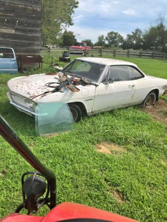

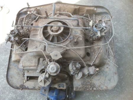
Engine removed from car
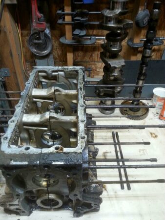

Engine after disassembly
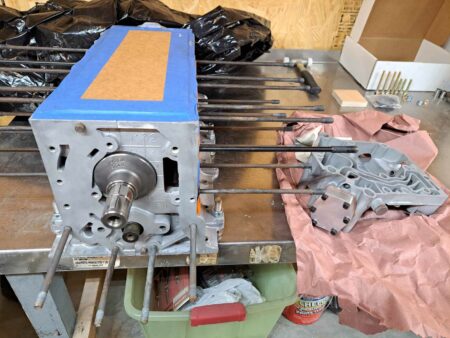

Bottom end as it returned from SPA
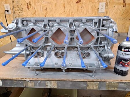

Bottom end after adding rear oil case, masking and painting
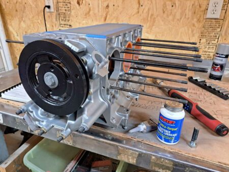

Masking removed and harmonic balancer added to rear of engine
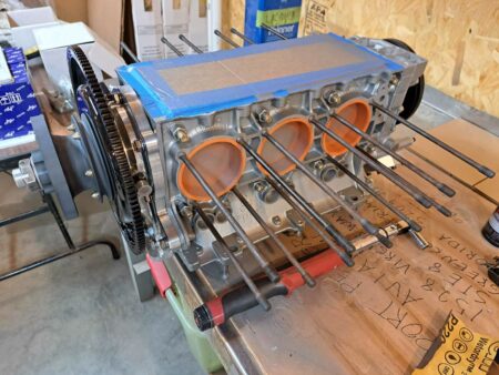

Prop hub and ring gear added to the front of engine
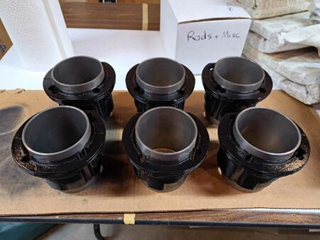

New cylinders painted
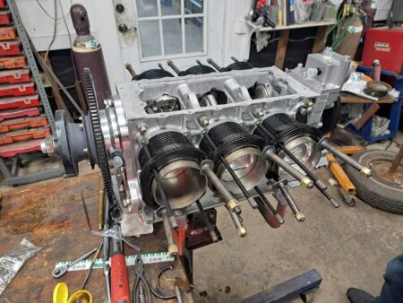

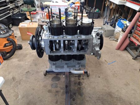
Now at William Wynne’s shop in FL. Rods, pistons and cylinders installed.
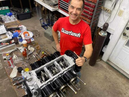

Showing off my Bearhawk gear

Engine is repositioned to install the head from the top and then rotated to install the second head from the top as well.
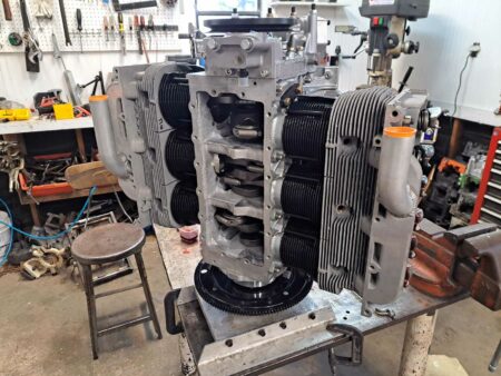

Second head now installed and engine moved to the vertical stand
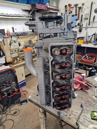

Valvetrain now installed
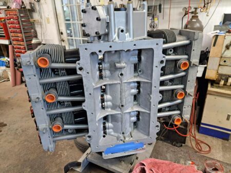

Ready to install oil pickup screen and oil pan
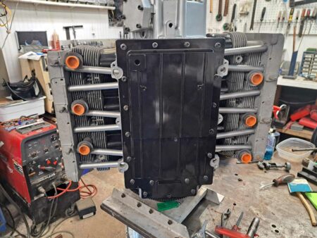

Oil pan now installed
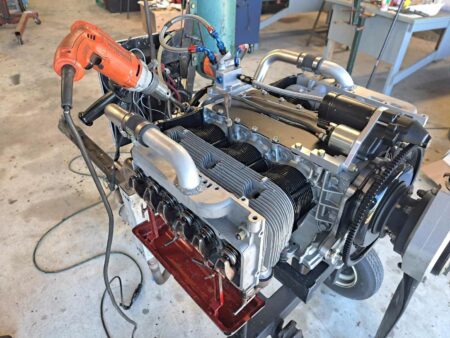

Engine has moved to the test stand. Top cover, starter and oil filter housing now installed. Drip trays mounted on heads to catch oil during pre-oiling process performed with drill motor spinning the oil pump.
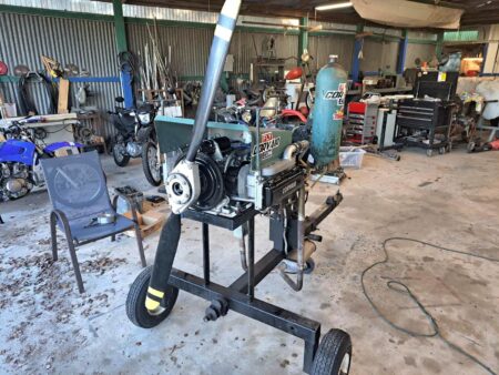

Pre-oil is complete, valve covers installed, and cooling shroud added in preparation for test run.
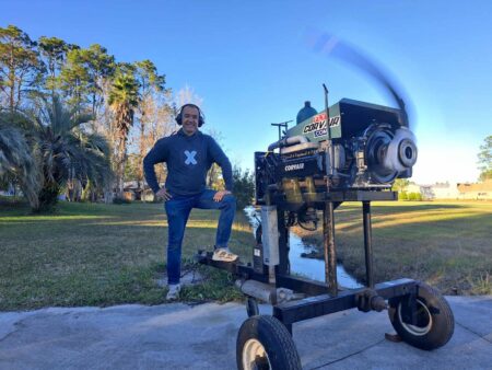

And it runs!
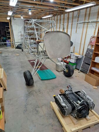

Back in Kansas, engine is waiting to be mounted on my LSA.
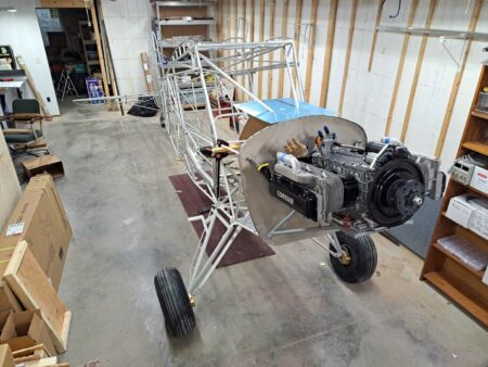

Engine mounted with William Wynne’s engine mount. The Corvair uses a bed mount.
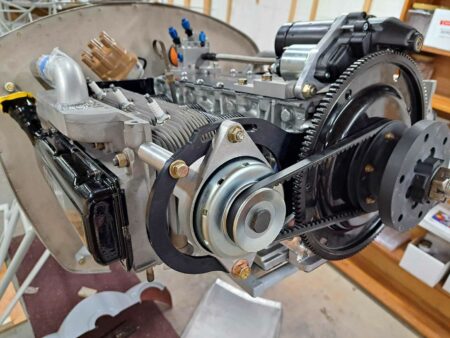

20A alternator now installed.
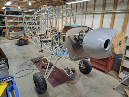

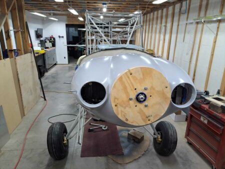
Nose bowl installed. This nose bowl is designed to use the 13″ spinner from Van’s Aircraft.
Cowl Modifications for Extreme CHT Cooling

Source: 2023 Q4 Beartracks
Scott Williamson lives in the Phoenix area with his Bearhawk 4-Place. He struggled to keep the engine cool, with high ambient temperatures and high horsepower not making things easier. In the end he fabricated a fiberglass cowl exit that made a big difference in temperatures. He also enlarged the inlets and moved them up and outboard a little. The mold for the new inlets was a dog dish. Thankfully most folks won’t need to pursue such measures, but these changes fixed the high CHTs for Scott.