Source: 2021 Q2 Beartracks Jared Yates
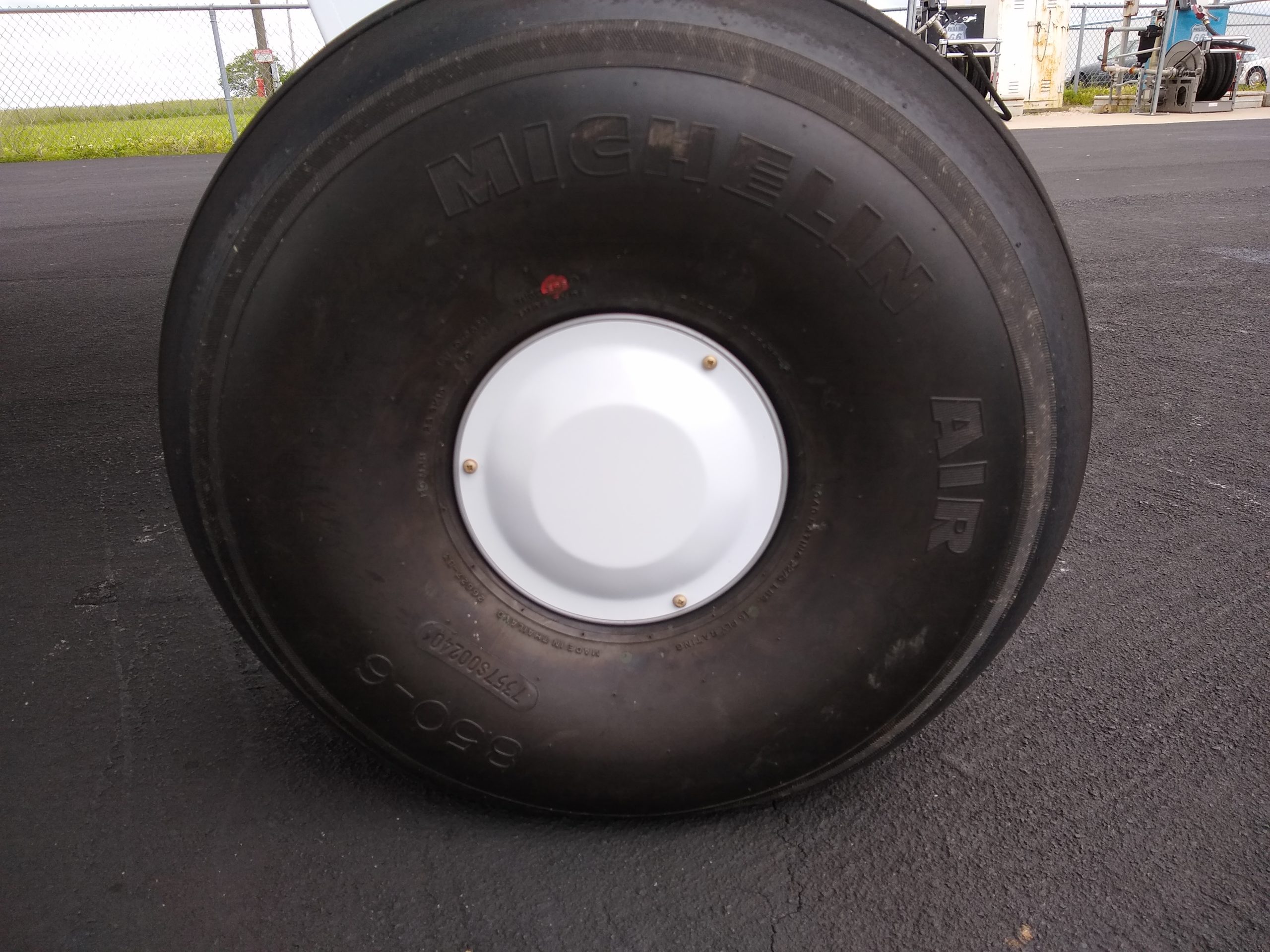
Last quarter we included a few responses from Bearhawk operators about how they prefer to manage their engines in cruise, and what speed they use on final approach. Here are a few more responses. Bobby Stokes in Arizona has flown around 320 hours in 3 years, and while his mission is varied, most flights seem to involve going places. He aims for 70 knots on final, slowing over the fence depending on the runway length. With 31” tires he gets 115 knots TAS at 8.5 gph, which is a loss of 10 knots compared to the 8.50 tires.
Dave Roberts in Montana has flown 930 hours since 2007. While he does takes some cross country trips, his primary mission is agricultural. He uses different speeds on final approach depending on the engine usage. At idle thrust, his target is 52 knots which leaves some margin for higher density altitude, but not below 46 knots. With a little power, he’ll use 42-43 knots, and notes, “Probably one of the most important things is to be aware of sinking. Not a problem to correct, just be aware. Especially at higher density altitude.” In cruise, he uses 1970 rpm and 22” MAP. That yields 112-109 knots at 9.5 to 10 gph. He says, “This is with a low compression 540. I’m in the process of putting 8.5 compression pistons in it now. It will go faster, but with the Bushwheels it really likes fuel when trying to push it over 113 knots.” At 2450 and 24.5 inches, he gets 130 knots at 15gph. At 2140rpm and 23.7 inches, 120 knots at 13.2 gph.
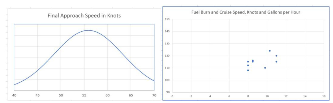
I’ve converted everyone’s answers to knots and gallons per hour to try and make it a little easier to compare, and also made some charts. Keep in mind that these data points are coming from a wide variety of engine sizes, a wide variety of tire sizes, and a wide variety of missions. Yet, there is certainly some centering. Take these values not as “the best the plane can do”, but rather as the “happy place” where operators have found good harmony and economy.
I think it’s noteworthy that none of these points is outside the realm of what an O-360 could do. We don’t seem to be selecting our engine displacement for cruise, but rather for the takeoff roll and the climb rate. I’m sure there are exceptions to this idea, and I’d love to follow up on this topic again with twice as many responses. The O-360 is the engine that the Bearhawk was designed around, which also speaks to Bob’s excellence in selecting that engine for the airframe, when it comes to cruise, drag, and economy. As we would expect, the data points do show a slight trend moving to the right as they move up, which relates increased speed to increased fuel burn. The noise in that sample comes from factors like tire size differences, and collection accuracy.
B. H. Carson (which I highly doubt is an abbreviation for “Bearhawk Carson”) has written about economy in our type of airplanes. Increasing speed above best glide speed leads to an increase in waste, but his point was that there is a method of operation which represents the least wasteful way of wasting fuel. Vastly over-simplifying his work, we can get to that point by multiplying best glide speed by 1.316. Without considering wind and speaking in round numbers, I found in our airplane that the Carson speed at 1700 pounds gross weight was 80 knots, and at 2500 pounds, 97 knots. If you are flying without somewhere to be, those are handy numbers to keep in the back of your mind as you decide how to manage the engine.
As for final approach speeds, my favorite answers were that we are looking outside of the airplane to decide how to fly it, at least from the fence inbound. Energy management on final is crucial to keeping enough energy to flare, but not excess energy that we must lose in a float. Experienced Bearhawk pilots aren’t staring at the airspeed indicator, but that doesn’t mean they haven’t mastered energy management. We are setting up a good pattern and stable approach at a good speed, and validating our visual cues with either indicated airspeed or AOA. For the last few seconds, it’s a matter of managing the elevator to execute the best kind of landing for the runway surface.
The chart below to the left shows the distribution of speeds, with the average being around 56 knots. It’s worth noting that the curve is pretty wide and flat, meaning there’s a fairly wide range of speeds for the paltry sample size that we have. The chart below and to the right shows the fuel burn vs cruise speeds.
The First Bearhawk Companion Completes Phase 1 Testing
Source: 2021 Q2 Beartracks
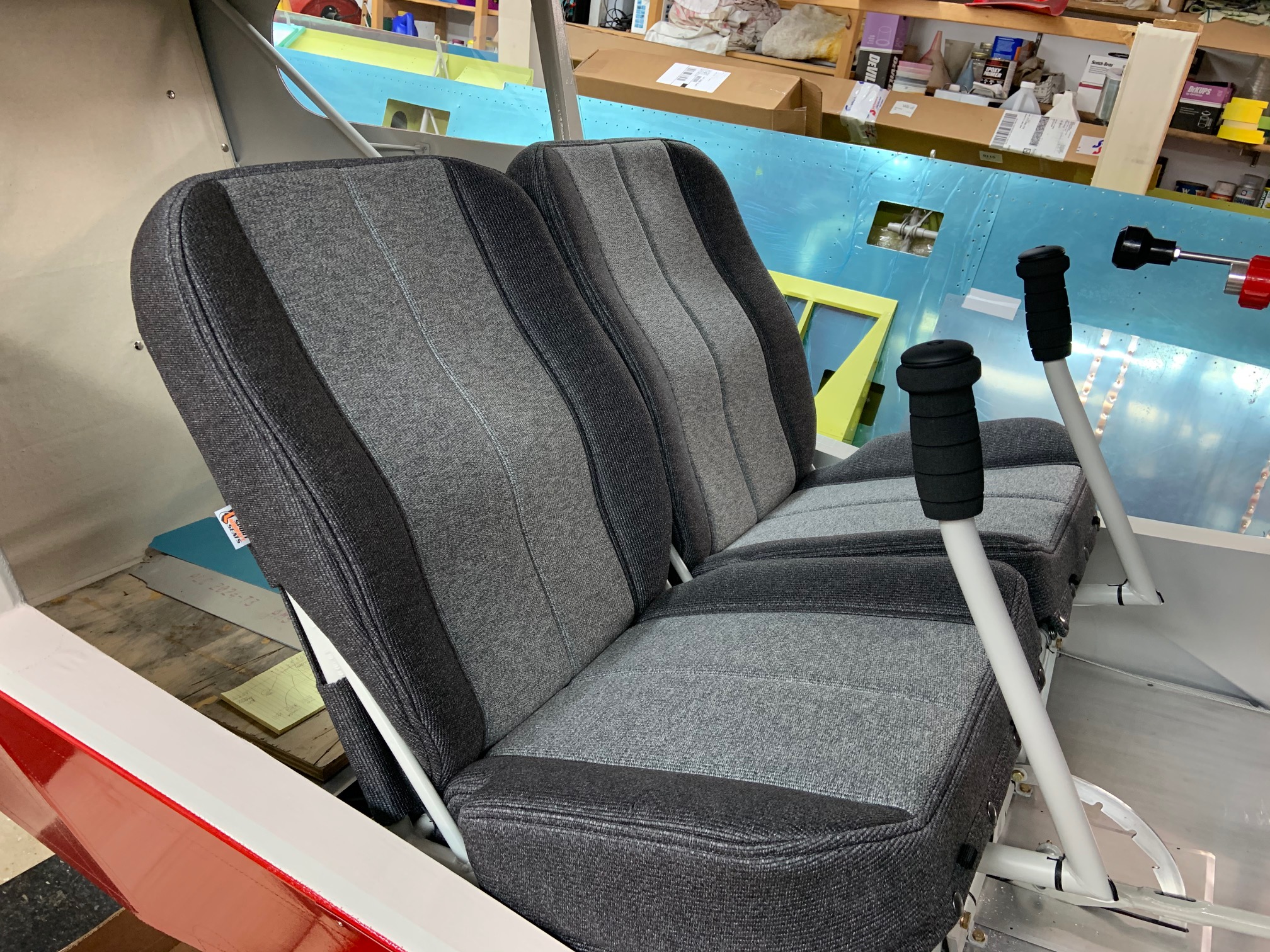
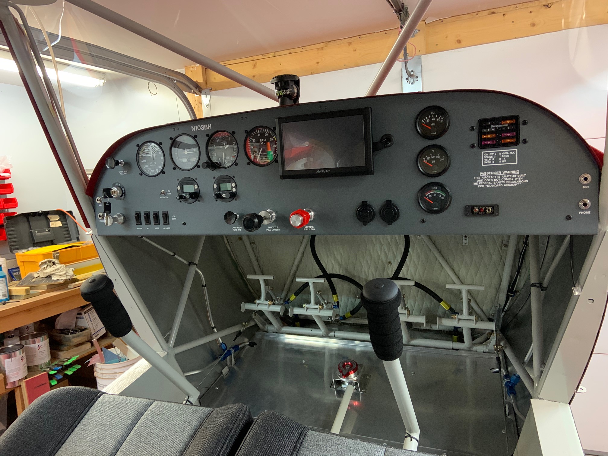
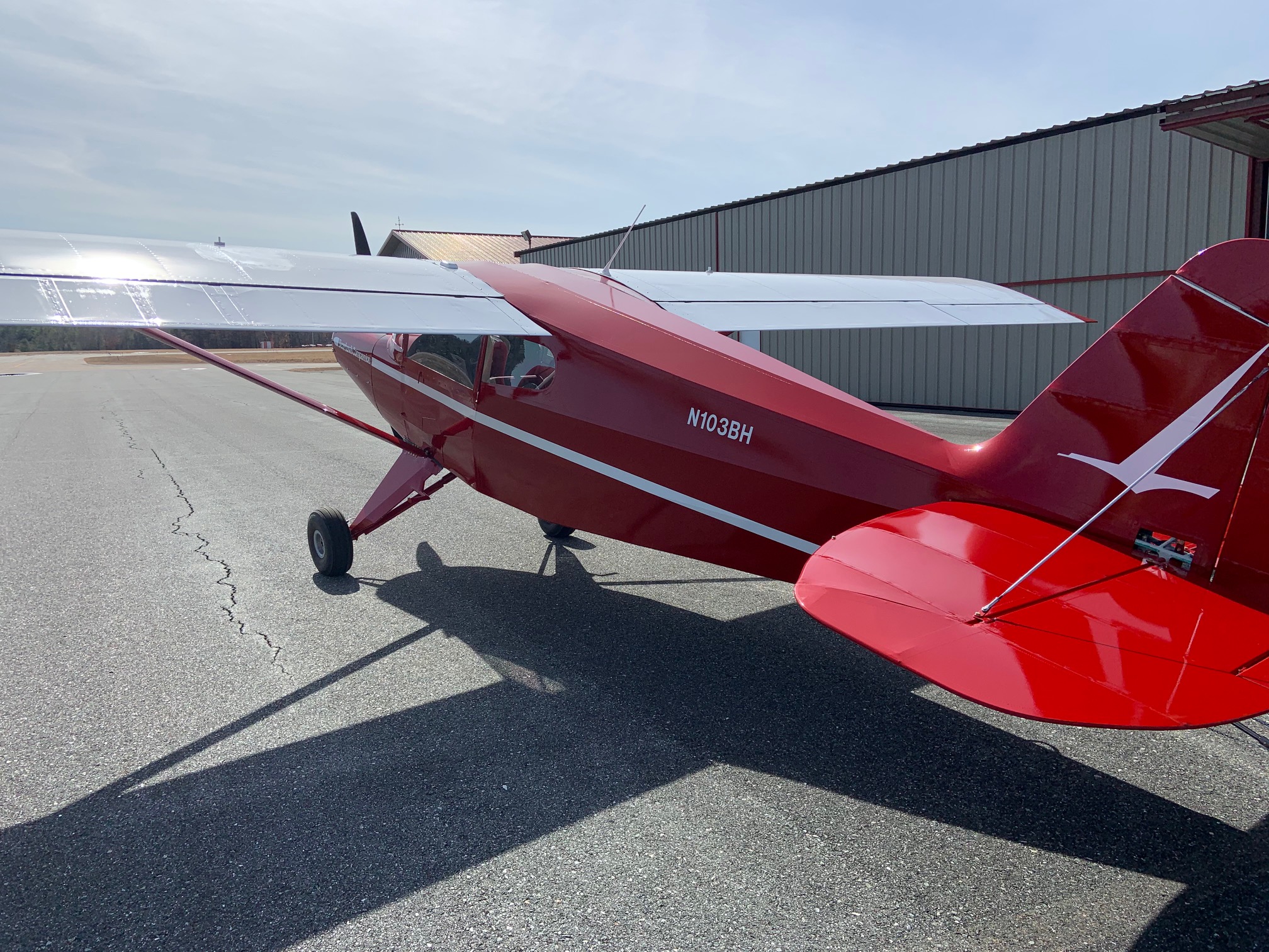
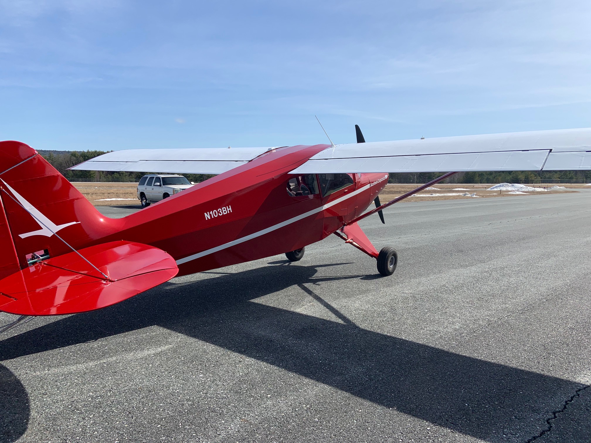
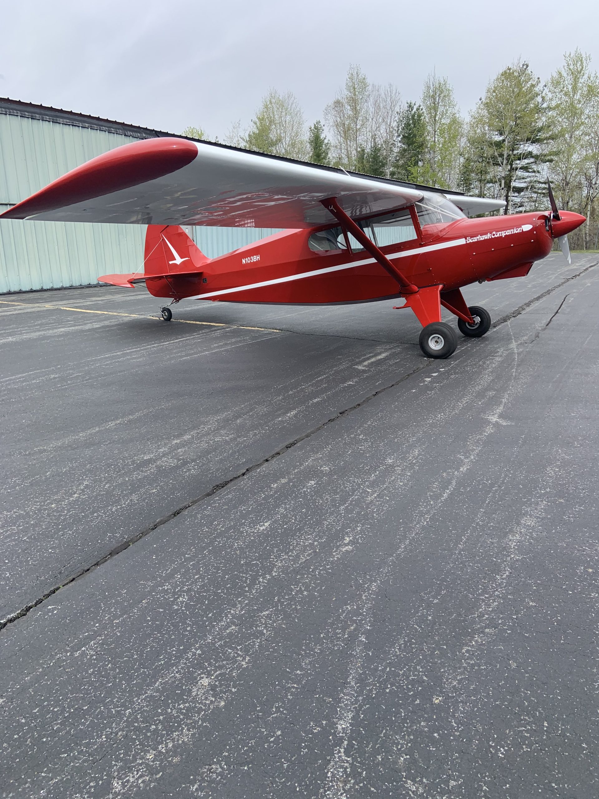
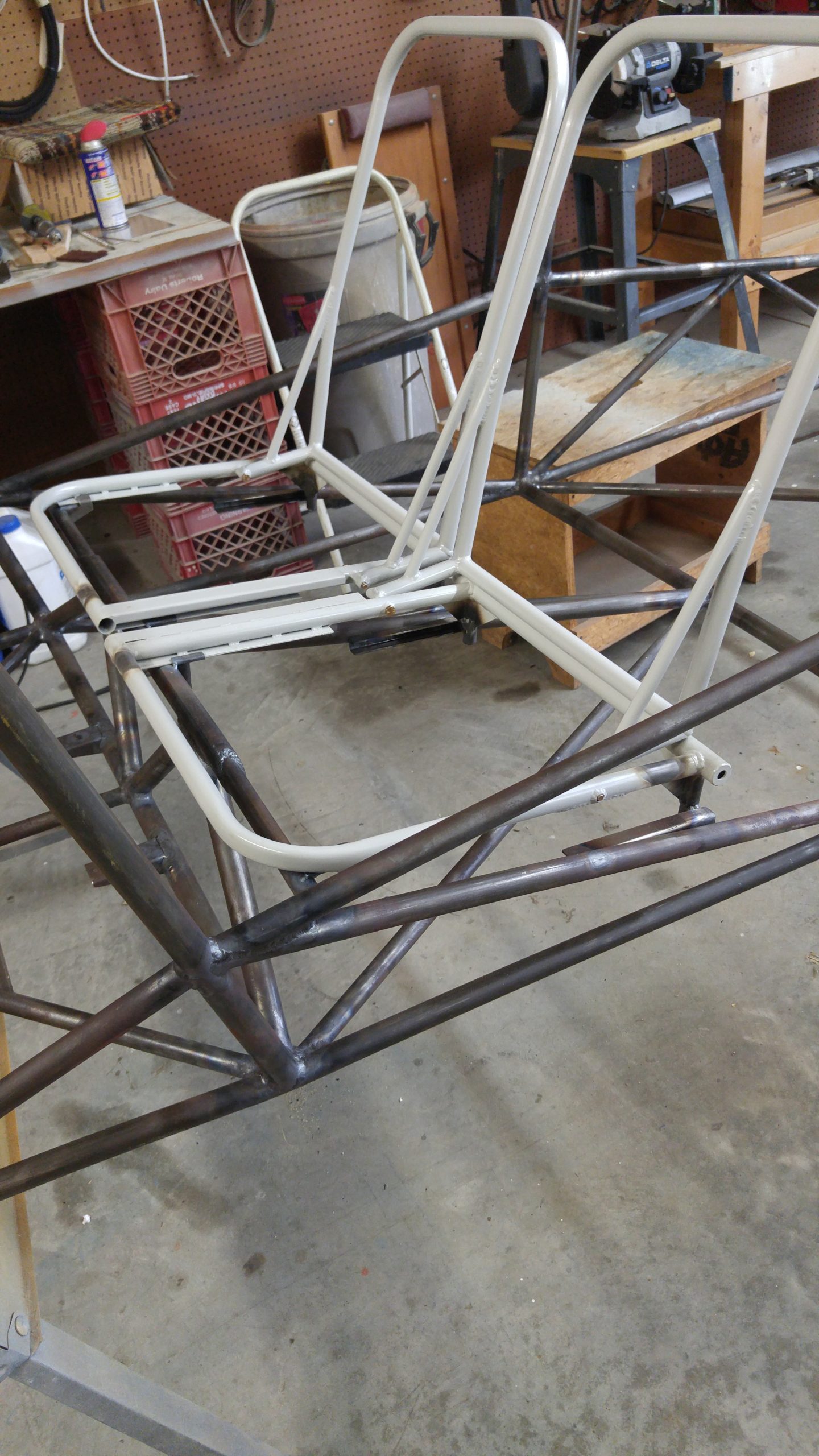
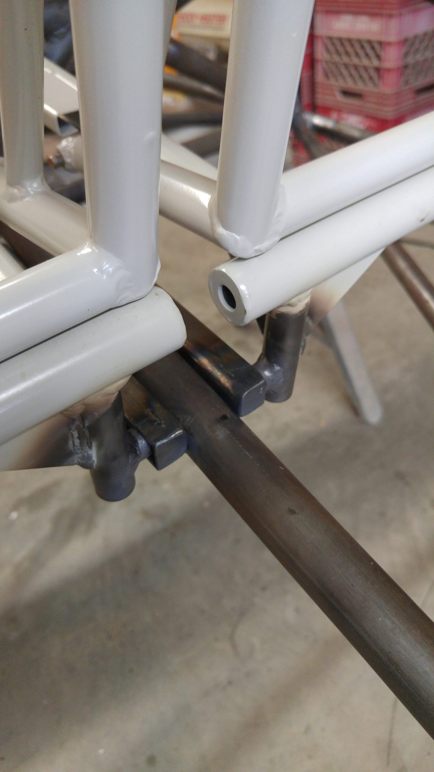
Dave Lenart reports completing the phase 1 testing of the first Bearhawk Companion in Vermont. Dave had previously built a Bearhawk 4-Place with an angle valve 360 and a constant speed prop. In many ways the Companion flies and performs much like he remembers the other one did, even though the Companion has 10-20 less horsepower with its parallel-valve engine and a fixed-pitch prop. The engine mount is 6 inches shorter, which makes for better visibility over the nose. He feels more favorable handling in pitch when compared to the 4-Place and more so when compared to the Patrol, because more of the weight is centered around the CG. Dave found it to be a little faster on the top end due to the design drag reductions (126 knots IAS), and a little slower on the low end due to the lighter wing loading. It stalls at 38 knots with full flaps and 42 knots clean. The operational number for baggage capacity is 250 pounds, and Dave thinks it will be a great candidate for floats, because of the huge useful load. Dave was also very pleased with the seats, which were covered by Daniel at Sport Aircraft Seats in Alaska. Now that Daniel has the patterns for the seat frames, he’ll be able to make seat covers and foam kits for other Bearhawks and expects to have pricing and ordering information available soon.
Bearhawk 4-Place Operational Numbers
Source: 2021 Q1 Beartracks, Jared Yates
As you hopefully know, I’m able to offer Bearhawk transition training to builders who are getting ready to fly their airplanes but would like to get some Bearhawk experience first. This is a very niche offering, with very few folks needing the training, but it can be especially beneficial when applicable. My main focus of the transition training has been on success in the first few flights, rather than the long-term operation of the airplane. When it comes to things like the best speed to fly on final, or the best power settings to use in cruise and what they yield, I know what works for me, but I find myself saying “be sure to ask a few other guys to see what they say.” To better equip myself to answer such questions, I asked a few operators and will summarize some of their answers. If you are flying a Bearhawk and can answer these questions, please reach out! These are all original Bearhawks, not the Model B. I have converted the answers into knots and gallons for easier comparison. The questions are, How long have you been flying your Bearhawk, and around how many hours do you have flying it? What type of mission do you use it for primarily? What speed(s) do you like to fly on final approach? What fuel burn and speed do you use for cruise settings? Personally, I’m at around 450 hours of Bearhawk time over 7 years. I primarily do short local flights with occasional longer trips, seldom at very heavy weights. I plan on 65 knots on downwind and base, with 60 crossing the fence, unless runway length is limited, in which case I use 50. I plan on 100-105 knots indicated at 8 GPH, which is usually around 112-117 knots true.
Pat Fagan has 1150+ hours over 18 years. His primary mission is sightseeing, to scope out areas to visit on the ground, but he also still likes going off the beaten path to see old airstrips and camp. For speeds on final, he says, “I’m not a numbers person and whenever someone asks me about speeds I never have an answer for them. I have thousands of hours in various aircraft towing gliders so my flying is almost totally attitude flying with eyes outside the cockpit. I do have an AOA indicator that I pay some attention to on final but I couldn’t tell you what speeds I’m indicating at various points in the pattern.” For cruise planning, Pat uses 20” and 2000 rpm at 10 gph.
Larry Sullivan has 625 hours in 6 years, primarily short cross-country legs (lunch and breakfast runs, travelling with bicycles) and occasional longer trips. He shoots for 65 mph (56 knots) on final and feels like he could go slower if he practiced first. He gets 116 knots at 8.5 gph, which is 65% power.
Mark Scott has 545 hours in 7 years, with a couple trips from Connecticut to Alaska, plus lots of local rides, and he’s currently training in his Bearhawk for his Instrument rating. Regarding final approach speed, Mark says, “Flap speeds (knots) are 85 1st notch, 75 2nd notch, 65 3rd notch, 55 4th notch. The even 10 kt spacing makes it easy to remember. I typically land with three notches and approach at 60 kt. If I’m doing short field work fly at 50-55 kts with full flaps, weight and wind depending. I would say 99% of my landings are three pointers. My best landings in terms of ground roll and bounce are where the tail wheel touches a split second before the mains. I have a T3 shock absorbing tail wheel unit and it is GREAT, nice and soft and I have not had shimmy since changed over.” For cruise settings, Mark uses 23” at 2150 rpm, and gets 125 knots true above 5000’.
Ray Strickland has 360 hours in 2.5 years and does lots of local flights under 2 hours, XCs less than 1 hour, and occasional longer trips. He flies 58-60mph (50-52 knots) on final at full flaps with the throttle idle. In cruise at 23.5” and 2400 rpm, he’s getting 108 knots true at 8 gph.
Jonathan Battson has 850 hours over 7.5 years, and flies lots of backcountry XC legs. He flies an AOA on final that yields 40-45 knots depending on weight. In cruise he gets 120 knots TAS at 10.9 gph.
Jon Wheeler has 70 hours of Bearhawk time, mostly family hauling trips. He shoots for 60 knots in the pattern but doesn’t focus too much on airspeed on short final, instead prioritizing outside visuals. If runway length is a concern, he aims for 56 knots on final. In cruise, he plans for 112 knots at 8 gph.
Zach Kelley has 120 hours in a little over two years. He flies an hour or so to backcountry destinations and for hunting and scouting game when the season is on, though he only likes to land at places where planes have been before, preferring not to rebuild his airplane every couple of years. On-airport he sets up for a 50 knot final with a bleed-off crossing the fence. Off airport, 45 knots unless he needs more visibility over the nose. He says, “Stall speed at gross is 41 and all but empty 39 so 45’s right there on the edge.” In cruise he sets 11gph at 2100 rpm and gets around 115 knots true. Next month he’ll be installing floats, which I hope we’ll hear more about.
Russ Erb has 747 hours in a dozen or so years of flying his Bearhawk. He’s an “on-road” flyer, airport to airport, with small tires and wheel pants, which he says yielded a 5-knot boost. Abeam the touchdown point, he’ll slow to 65 knots, and on final, 60-65 with flaps 3. If he’s wanting to keep it short, he’ll tend more towards 60, but he endeavors to touch the main wheels first. Local constraints keep him at high altitudes, and he sets the throttle .1” closed from wide open, and 2100 rpm. Then he sets fuel flow based on a chart, ranging from 11.4 to 9.2, at 5500’ to 12500’ respectively, yielding 122-125 knots TAS. Russ has much more data and says we might look forward to seeing that in a future issue.
These are just the first few answers, but I can see a few trends. First, several of us have found that there is a sweet spot in cruise in the 8-11 gph range. We have major variations in engine horsepower, but relating airspeed to fuel flow essentially eliminates that variable. While the airplane can go faster for more fuel burn, real-life missions seem to make that less desirable. Another trend is that these final approach speeds are more like three-point speeds in the 50-60 knot range, as opposed to wheel landing speeds in the 70-80 knot range. It’s not that the airplane can’t or shouldn’t do zero-pitch wheel landings, rather that it doesn’t need to, and seems to be happier at the slower, tail low speeds. I look forward to adding more data points and will share them in the next issue this summer.
Bearhawk Patrol Glider Tug Called “Lucy” Follow Up, Altitude Record
Source: 2020 Q3 Beartracks, Alan Arthur, Doug Harrington and Avon Furphy

Eighteen months have gone by down in Australia and Lucy has completed almost 100 hours and 85 glider tows.

Initially the Mazda 13B rotary engine was naturally aspirated and although the performance with around 180 – 200 HP was more than satisfactory for normal flying the performance towing a 600kg (1322 pounds) glider on a 40 degree Celsius day was not spectacular.
Early on we had a problem when the engine started to consume excessive amounts of oil, there were no leaks and the exhaust was not wet and oily, what was happening was that the engine runs so hot that the oil leaking into the combustion chamber was being burnt as additional fuel. At the same time the air fuel ratio indicator was showing an erratic mixture that could not be corrected by adjustments to the fuel map. Hindsight is a wonderful thing and now we know what causes erratic mixtures.
The engine had to be removed and the rotor oil seals replaced, on a Mazda rotary that means a complete strip down. The opportunity was taken while the engine was out to fit a standard Mazda turbo charger. That sounds simple but was anything but. The engine bay configuration and the engine mount necessitated a quite radical custom installation.

Starting with the fabrication of an exhaust manifold that placed the turbo charger behind the engine in a spot that was previously occupied by dual batteries and a few other accessories.
The batteries had to be moved to the rear fuselage to compensate for the anticipated additional weight forward of the C of G.
The exhaust system and mufflers had to be completely reworked.


The turbocharger needed to be restricted to a boost pressure of no more than 6 psi, the standard turbo engine had low compression rotors; ours had high compression rotors and the advice was that this combination of high compression rotors and high boost pressure would cause seal and pinging problems. The waste gate controller was modified so that it was producing a maximum of 5.6 psi.
The next area for rework was the intake manifold and throttle body. Space was a limiting factor, so the standard manifold was cut and welded to keep the intake system as low as possible and oriented in the easiest direction for the plumbing connections.


Space constraints dictated that an intercooler could not be fitted and was probably not necessary with the low boost pressure.

First engine runs proved to be very positive, boost pressure was spot on and manifold pressure was up to 42” at static rpm. Fuel flows had gone up considerably from around 35 liters per hour to 50 l/hr (9.2 gph to 13 gph).
One of our original problems before the turbo was having to run the ground adjustable prop in the full fine position to achieve acceptable RPM in climb. After the turbocharger was fitted, we had to increase the pitch to limit the RPM.
Glider towing times before the turbocharger were in the order to 9 minutes to 2000ft chock to chock towing a 600kg glider; after the turbo the times are in the order of 6 minutes. Lucy’s tow times now closely match the times that are produced by a Piper Pawnee. Our estimate is that Lucy is producing around 240HP
Thirty hours have been completed with the turbo with no problems of any kind. One of the most common problems with auto engines in aircraft is cooling and particularly during taxi and ground operations; our dual radiators and double sized oil cooler have proved to be up to the additional heat produced by the turbo.
Where to next? With the turbo charger the obvious question is how high will it go? When the ideal day came round, a clear blue sky and almost zero wind at any altitude it was time to borrow an oxygen system from the gliding club and see how high Lucy could climb.
A couple of practice climbs to 12500 ft and 15000 ft on previous days sorted out the radiator expansion tank problems and then a full throttle climb to 22000ft answered that question. Lucy’s operation ceiling is around 22000ft where the climb rate fell to around 100 ft/min. The Mazda rotary engine performed faultlessly and even picked up RPM as she climbed, no doubt due to reduced prop drag at higher altitudes. The real limiting factor is the pilot, not only do you need a good supply of oxygen the -38C outside air temperature means you need a good heater or very warm clothing.


What next, more glider towing and cross-country flights experimenting with prop pitch and cruising RPM with an aim to reach an economical cruise consumption.
First Flight of the new 3000-pound Bearhawk Five
Source: 2020 Q2 Beartracks, Jared Yates
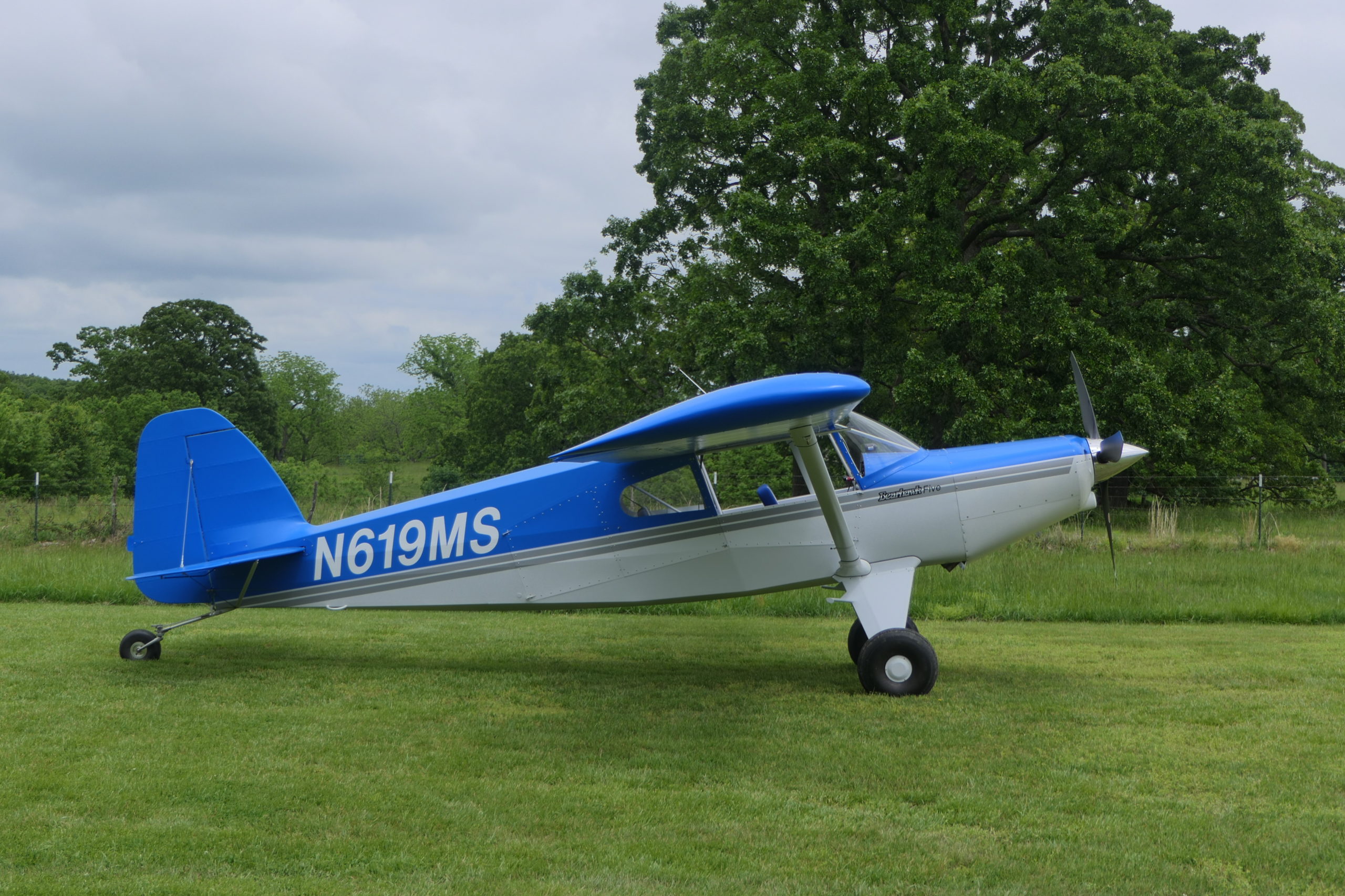
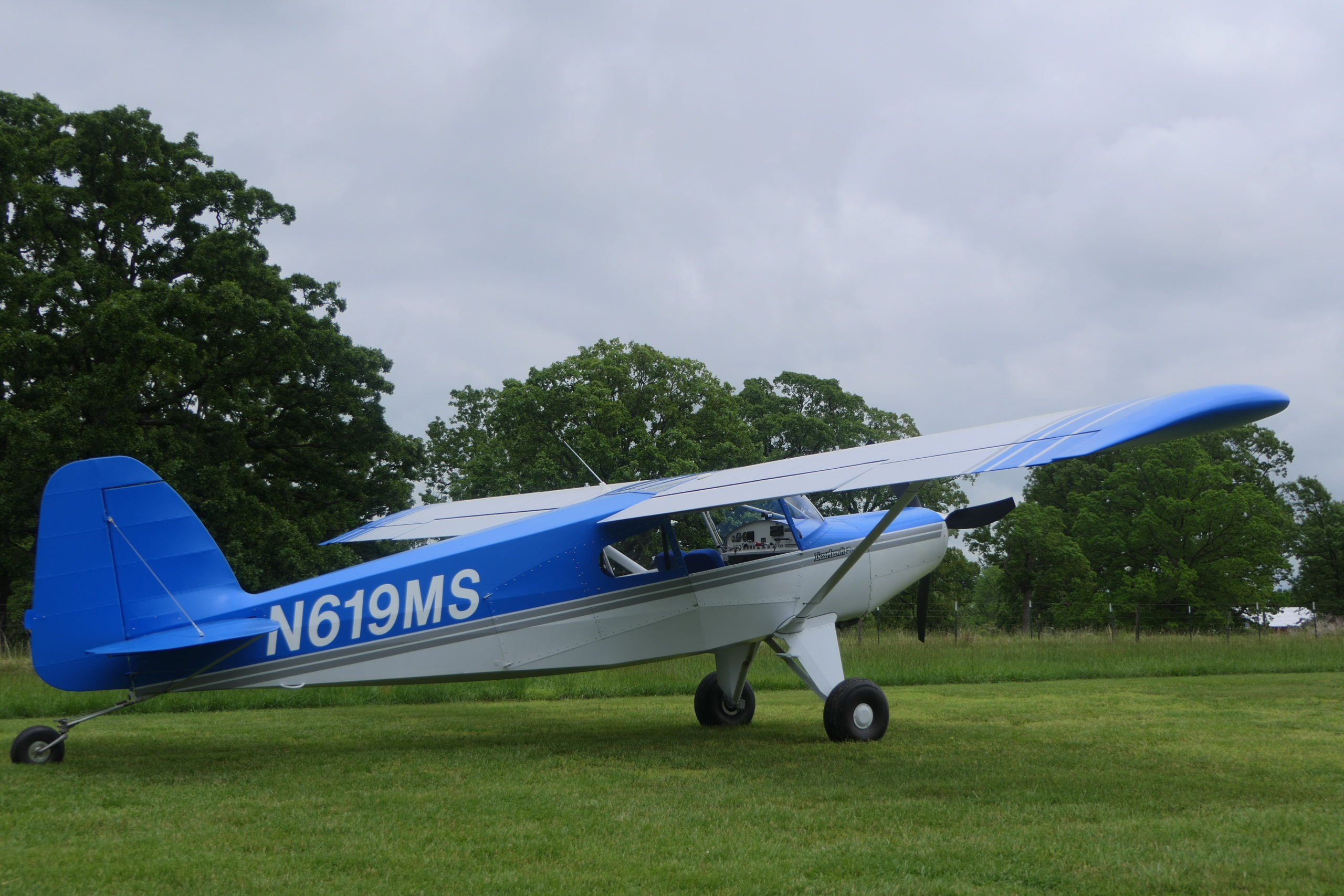
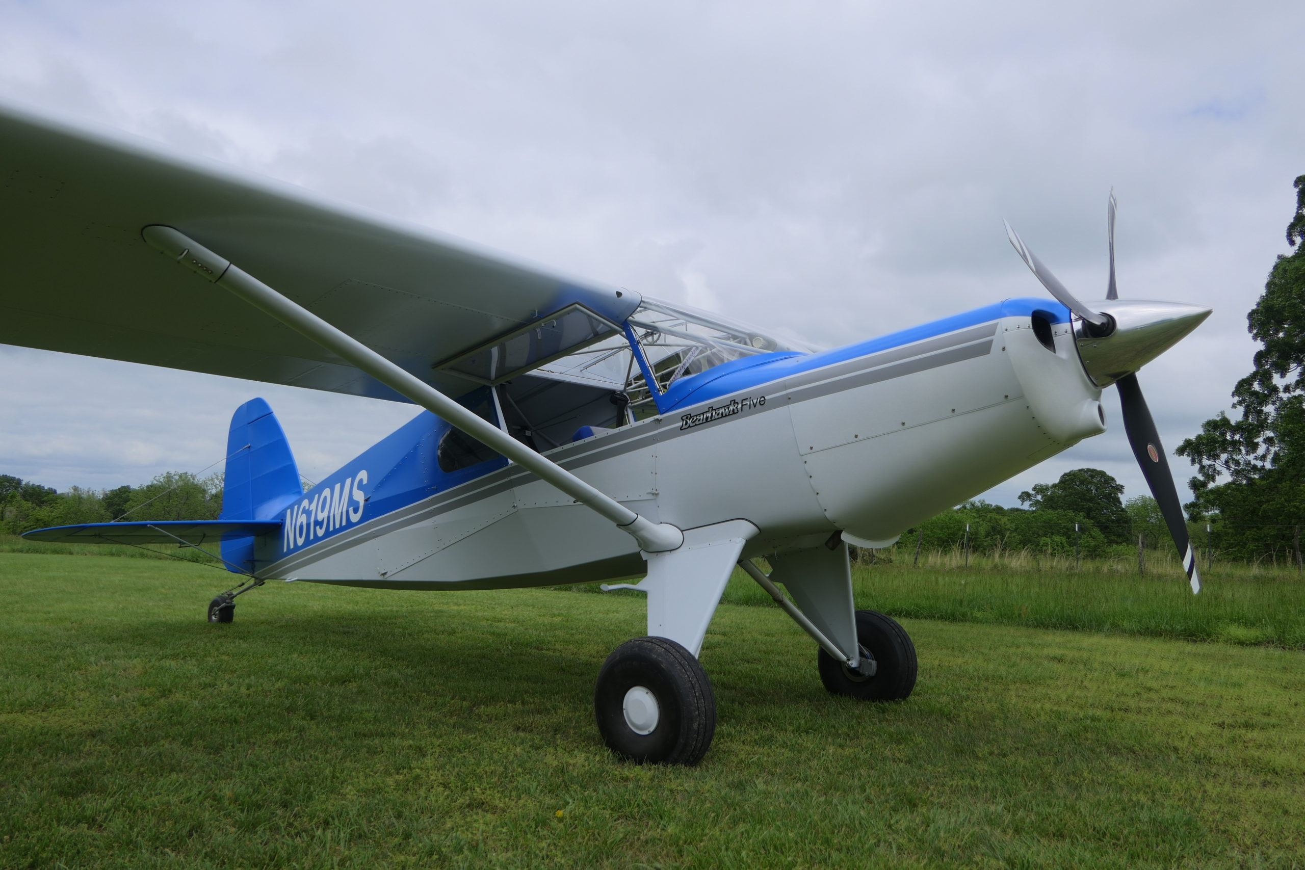
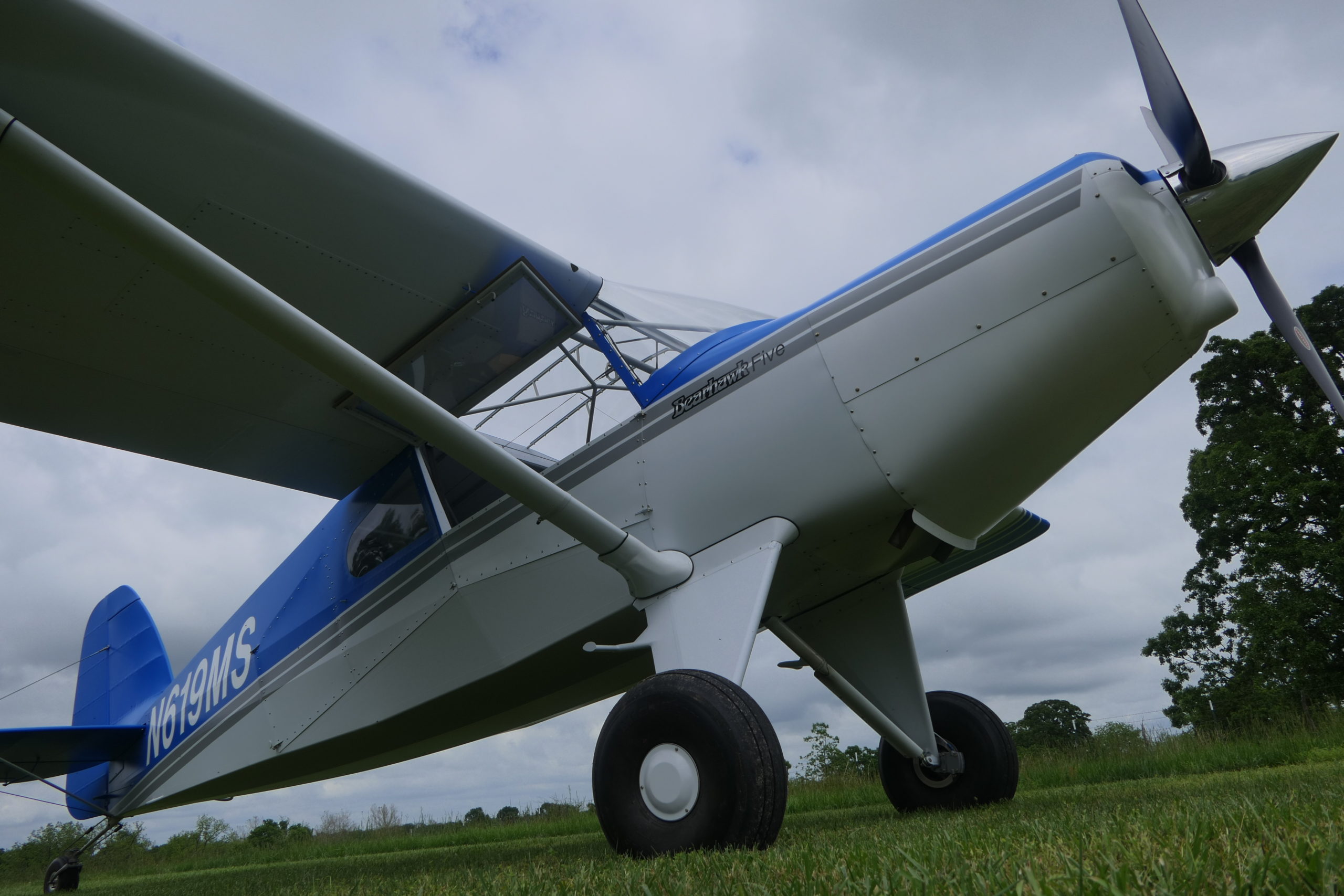
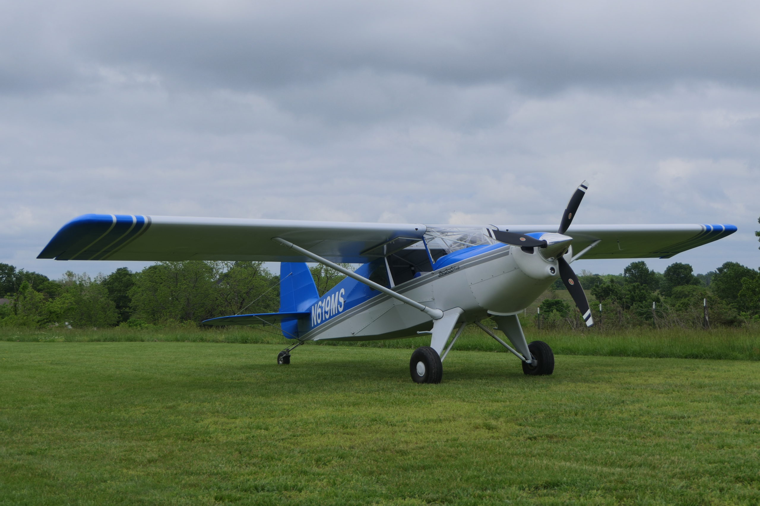
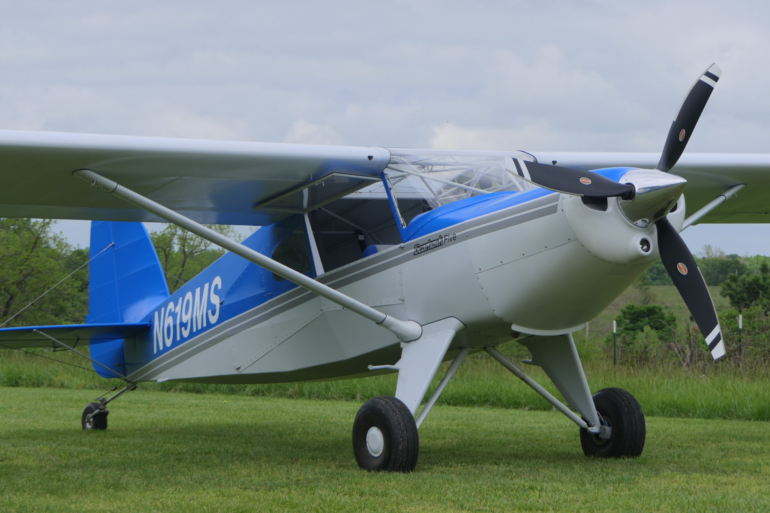
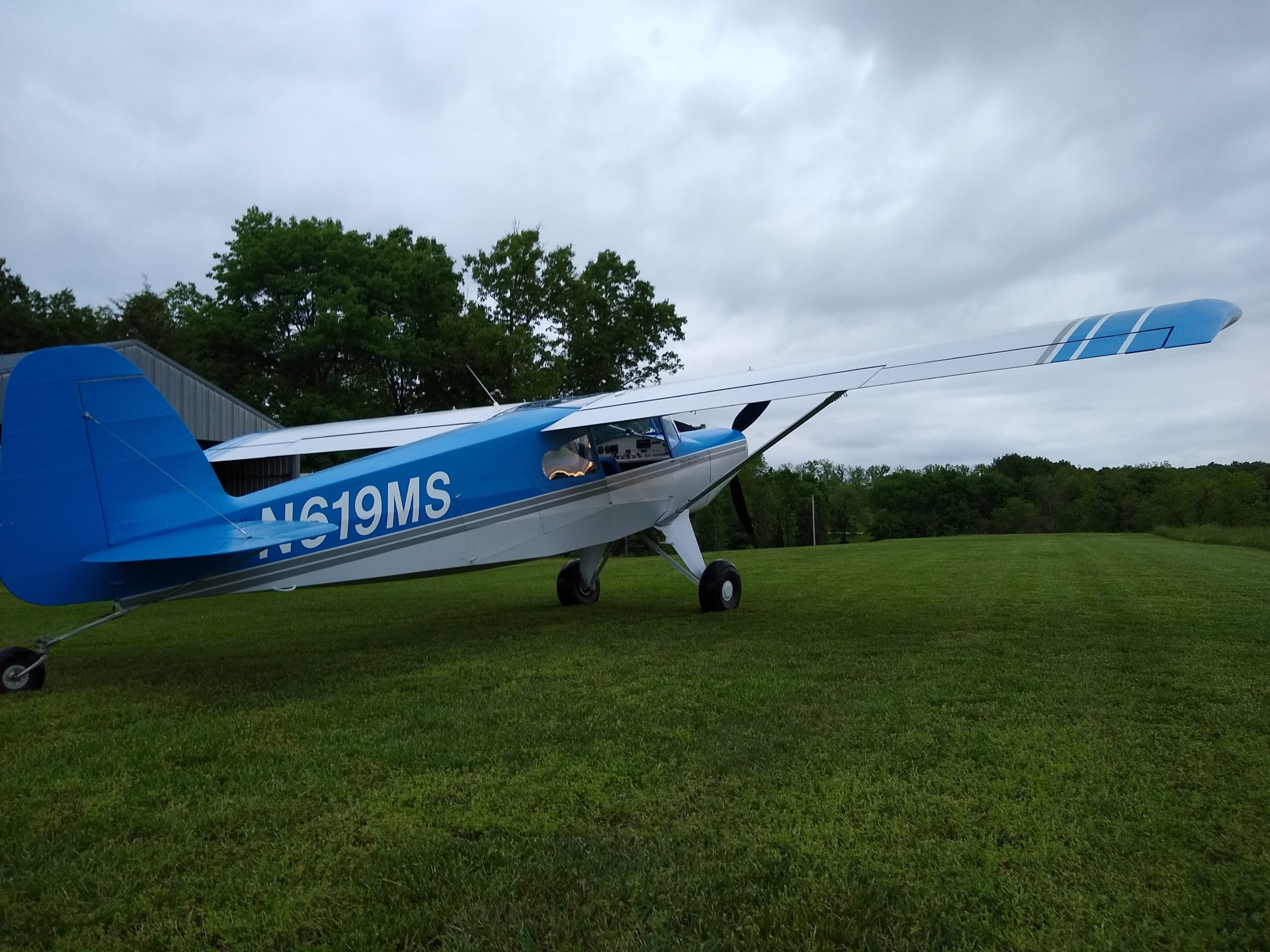
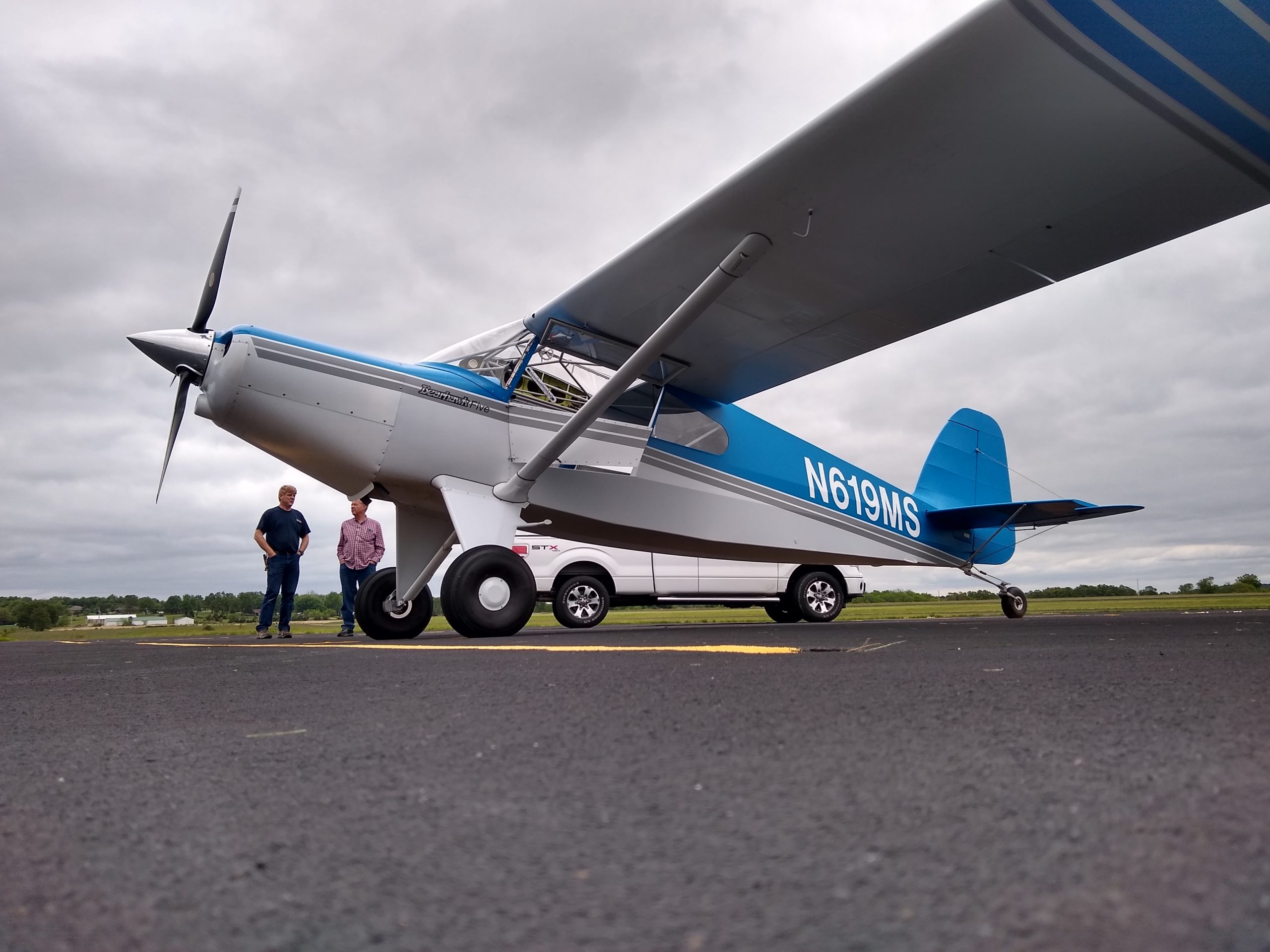
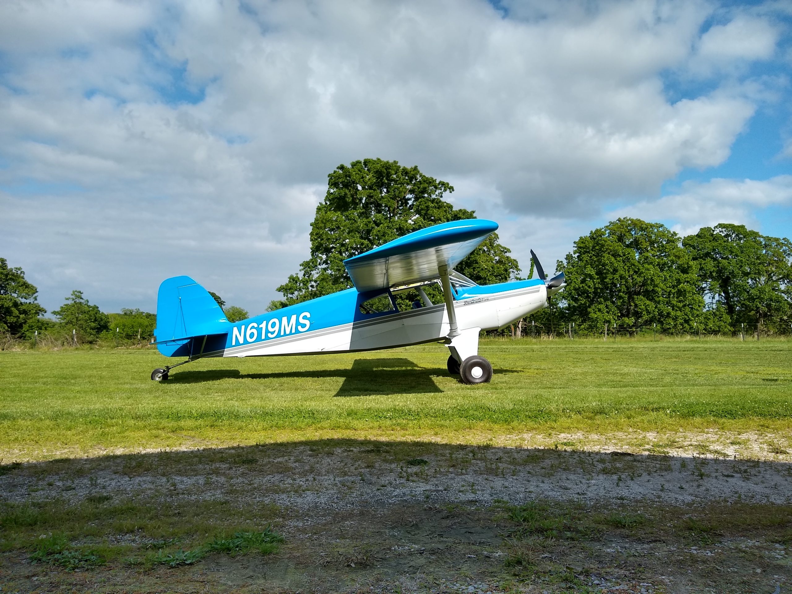
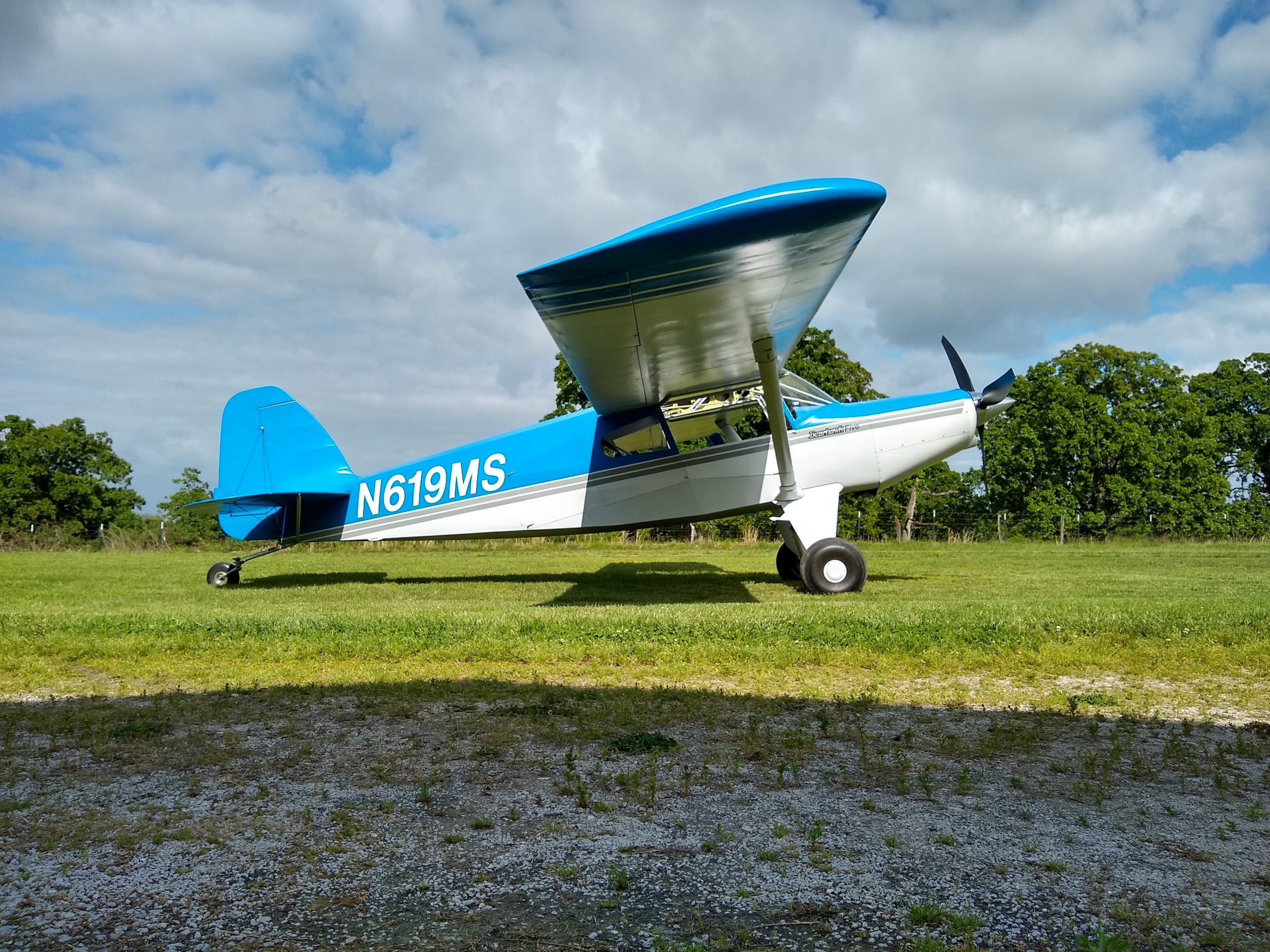
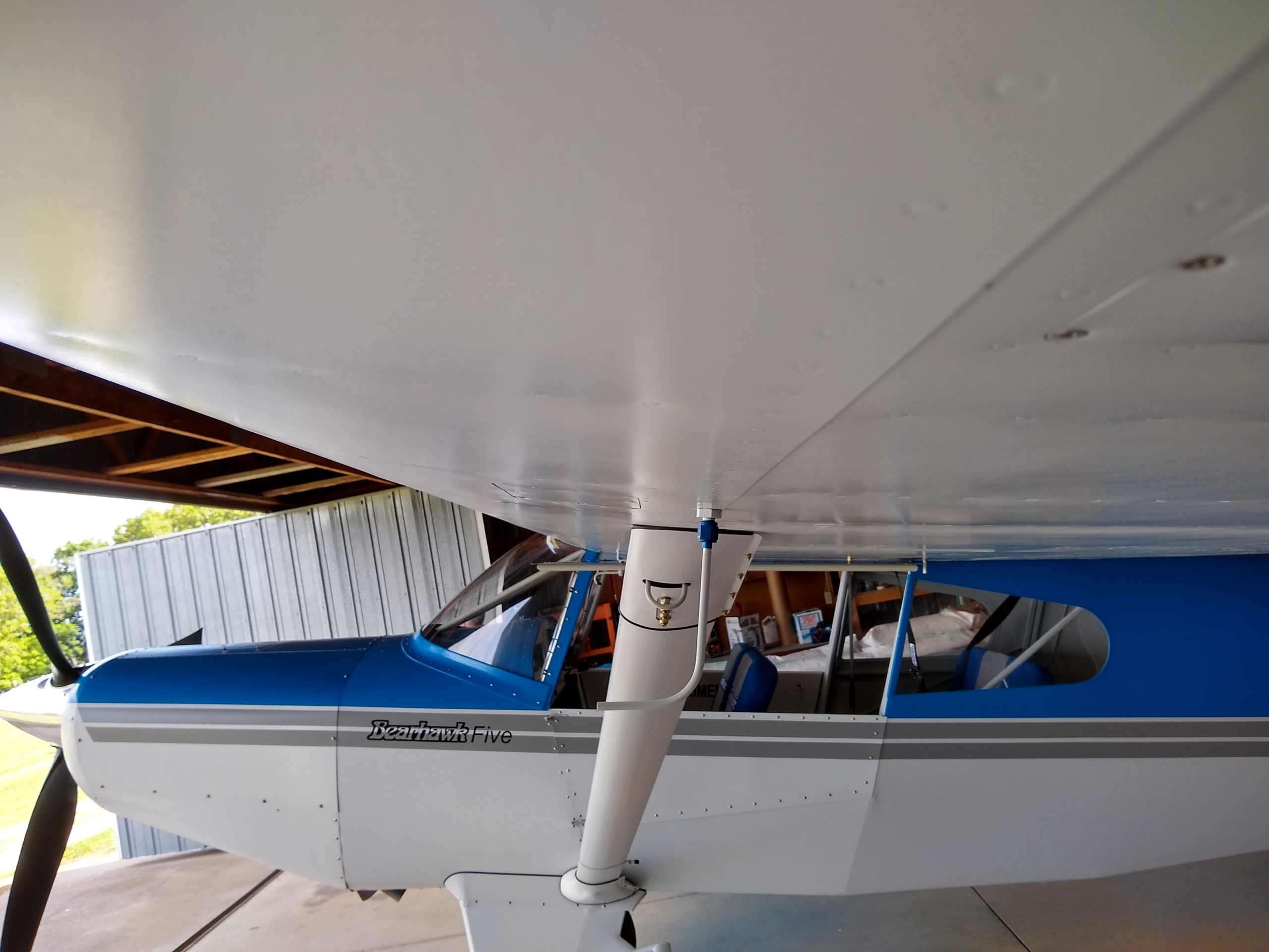
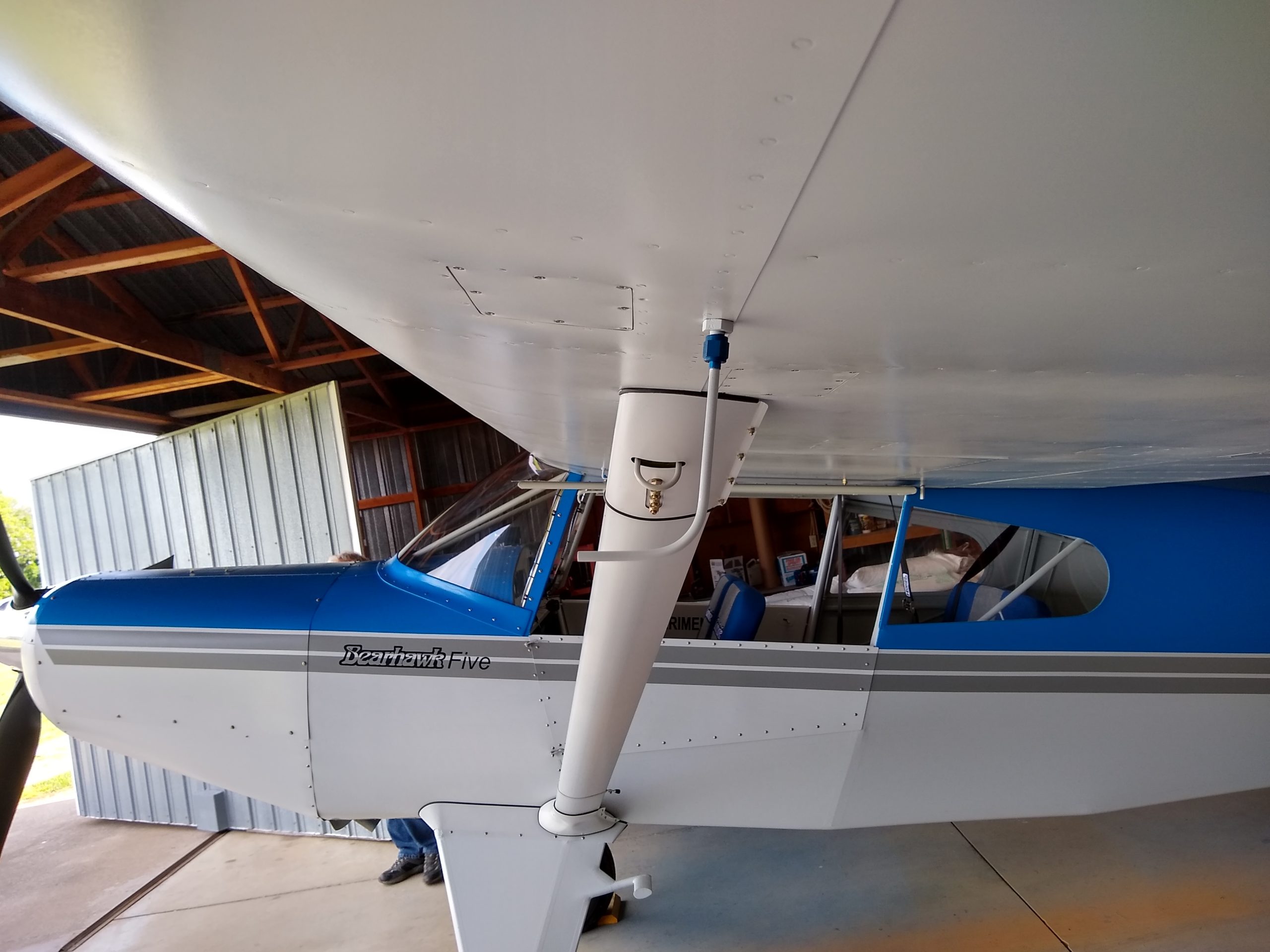
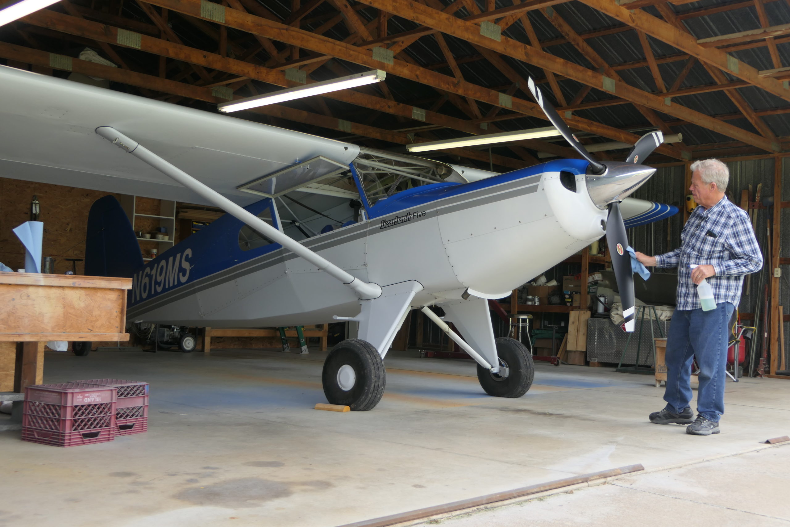
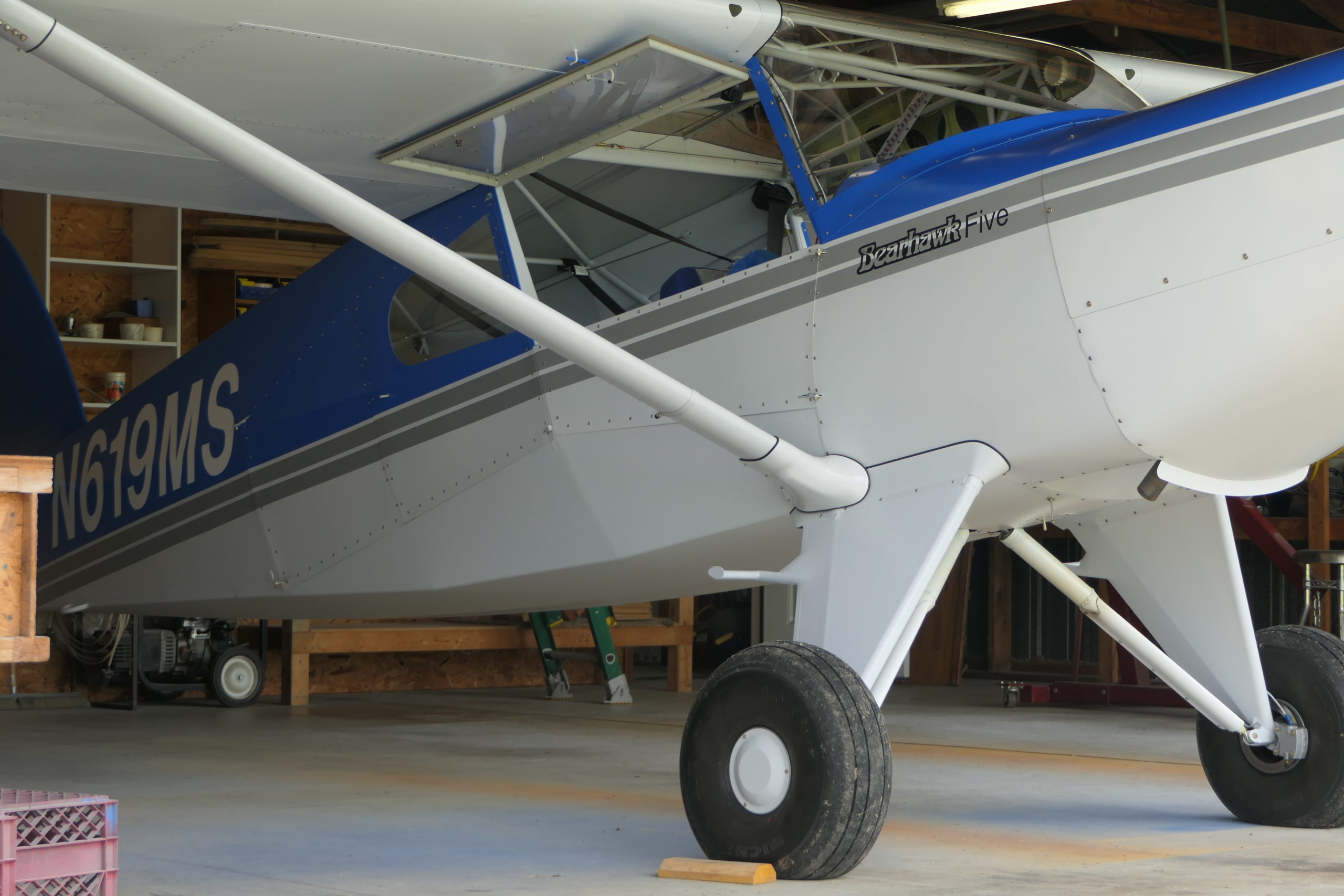
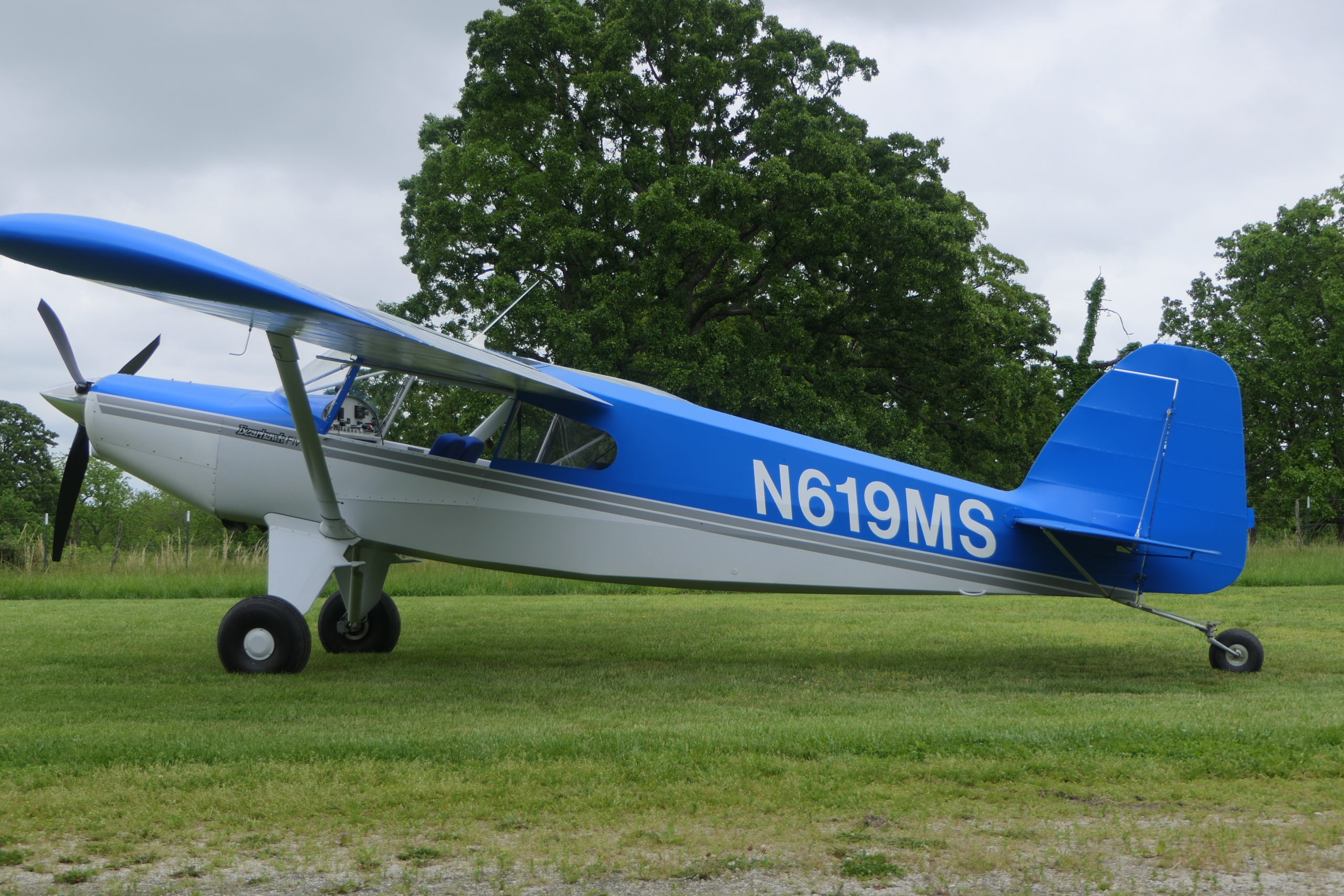
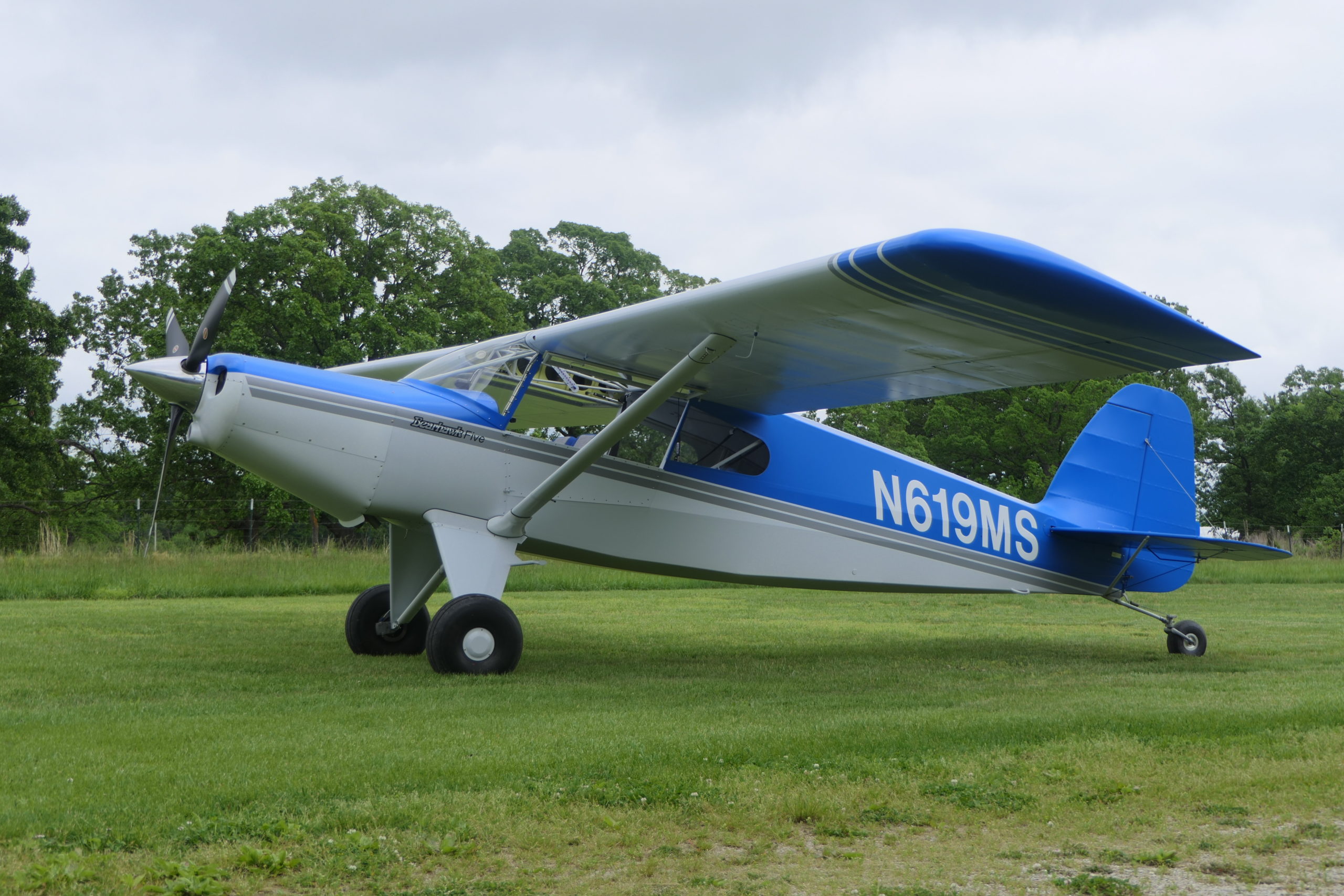
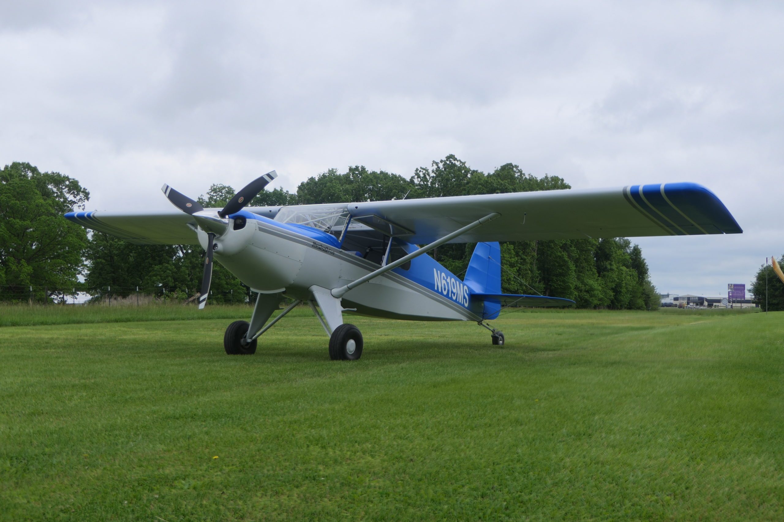
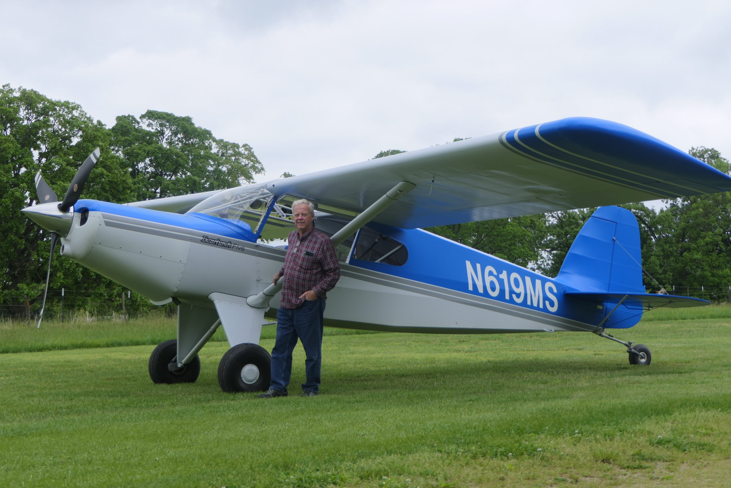
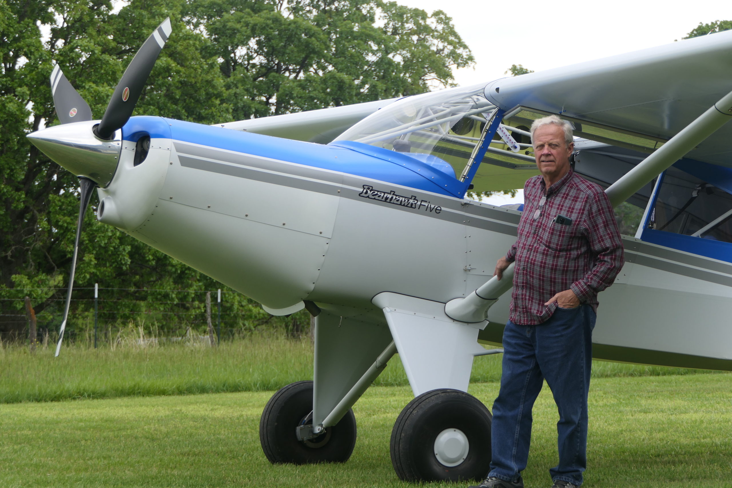
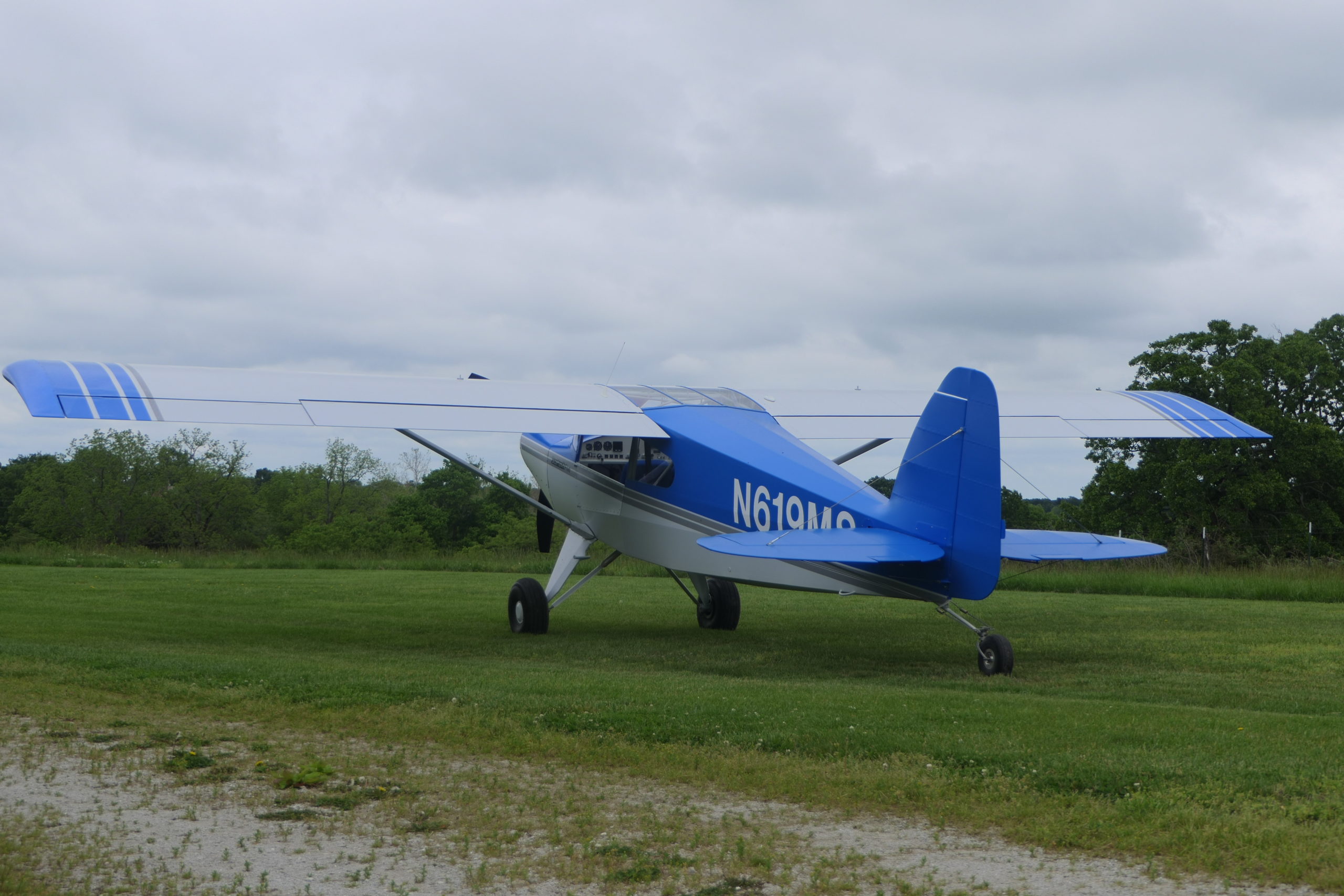
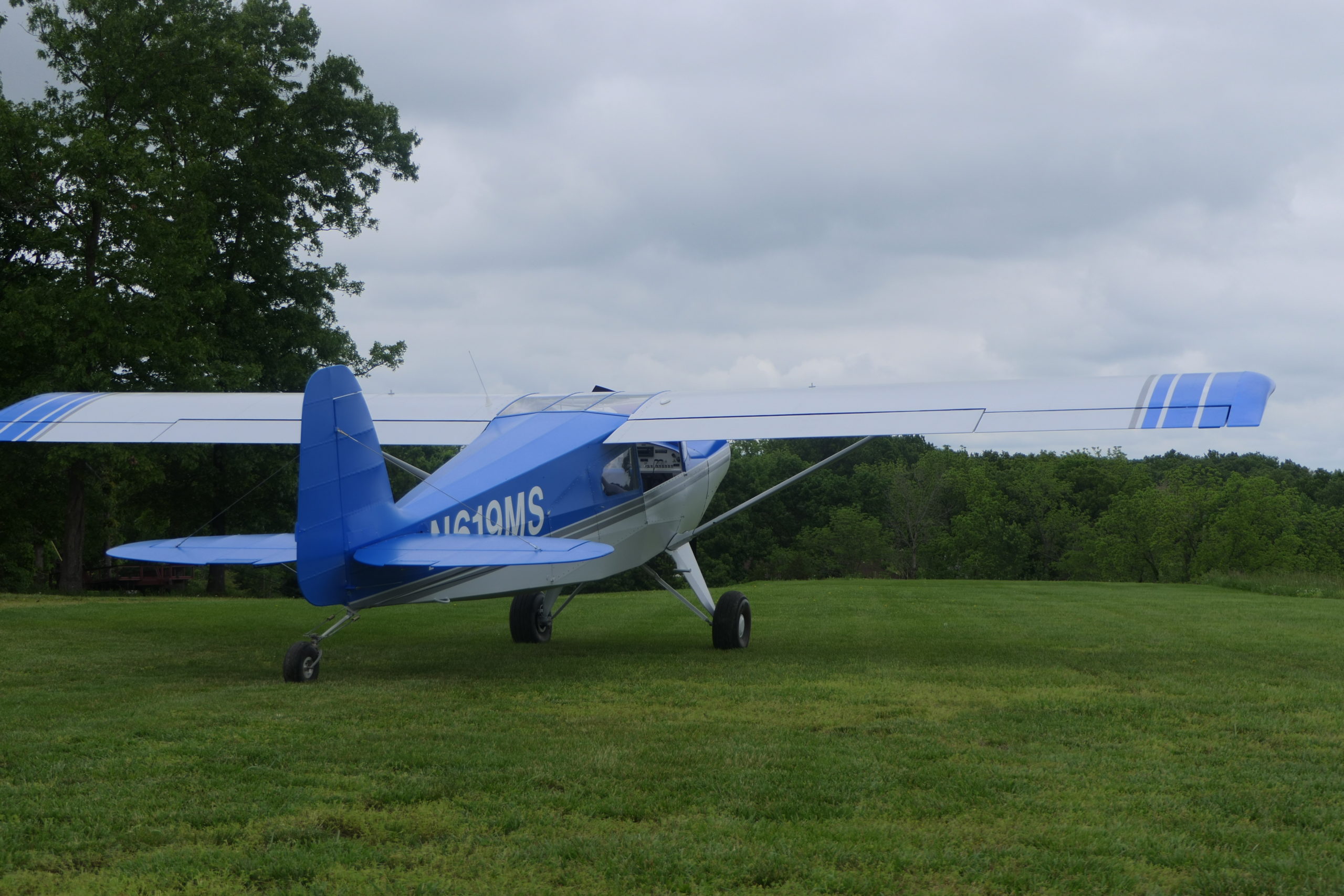
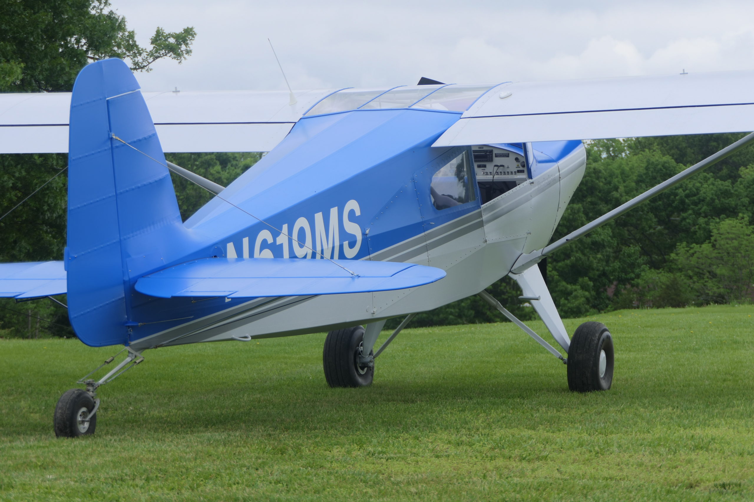
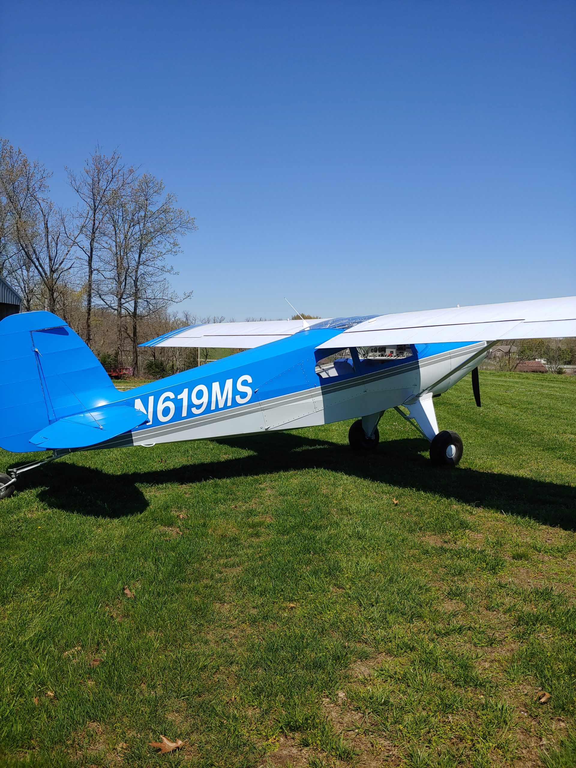
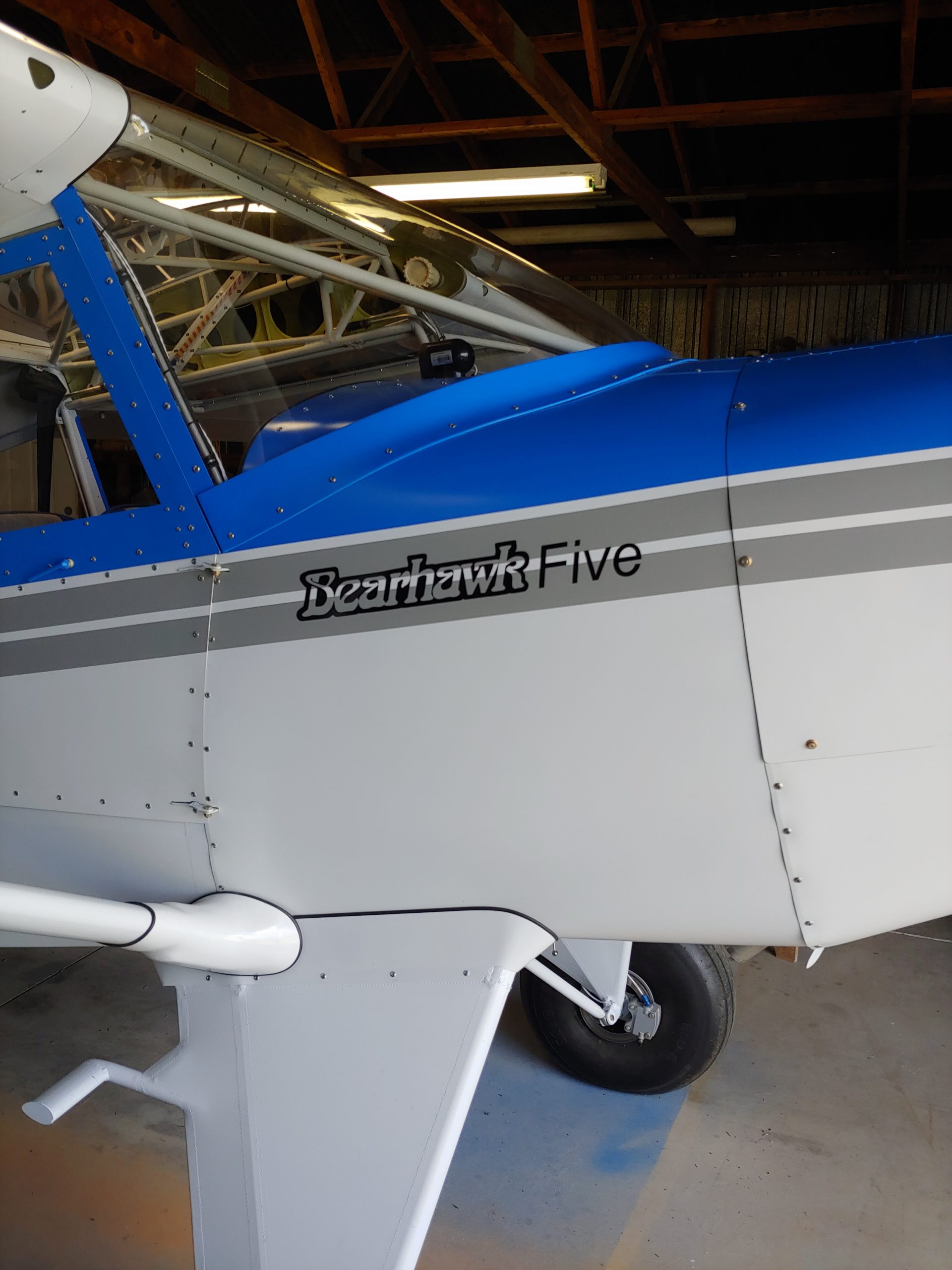
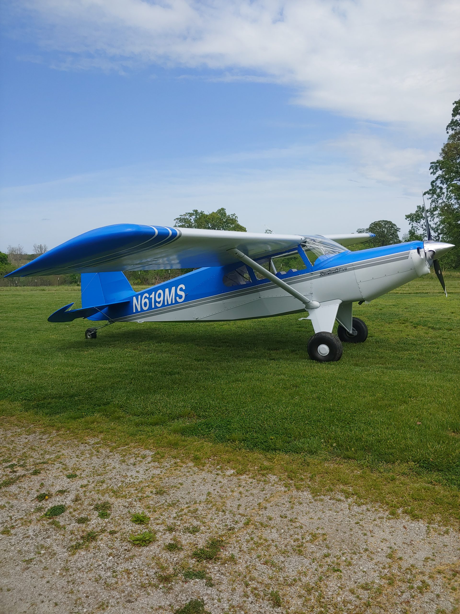
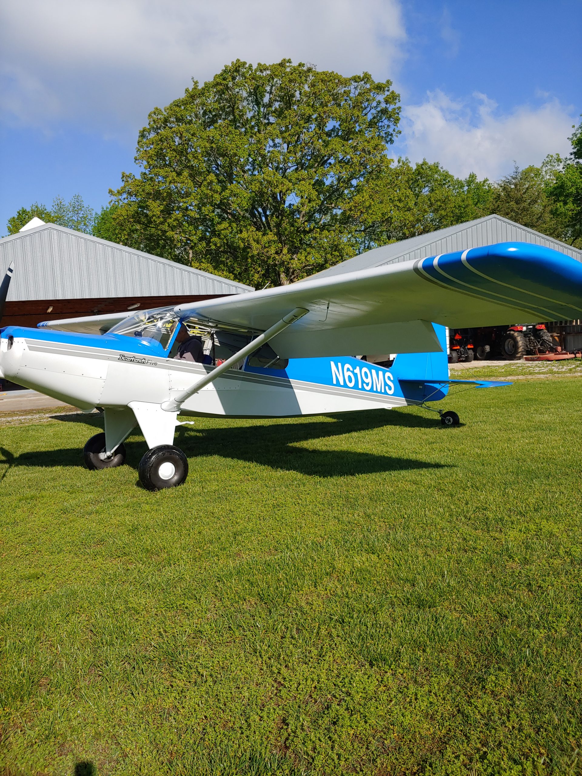
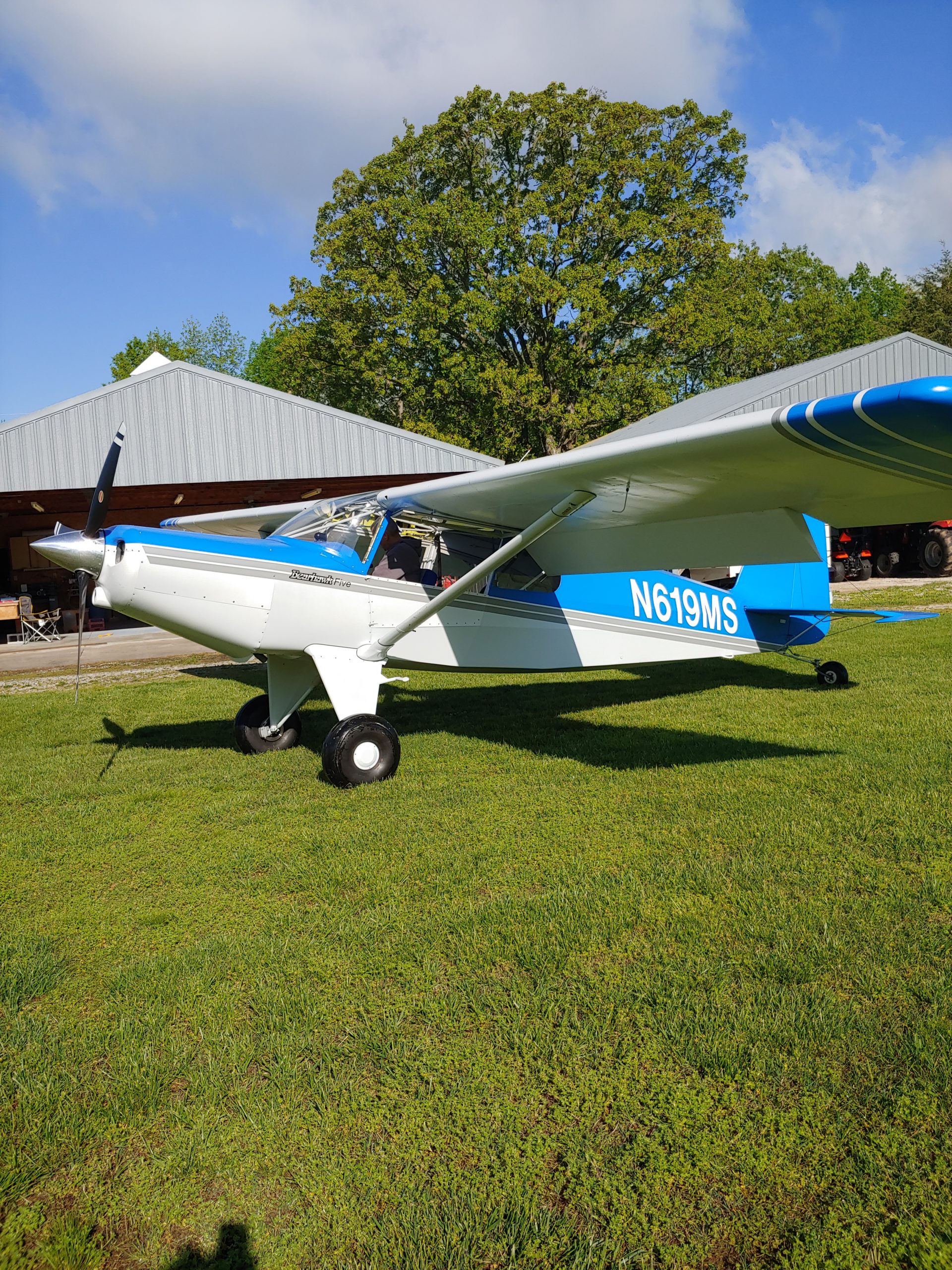
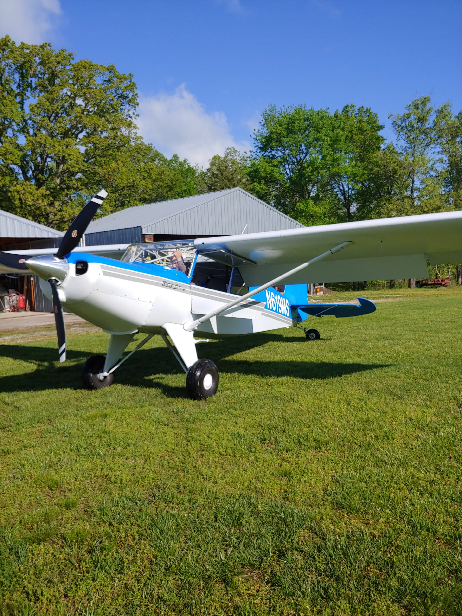
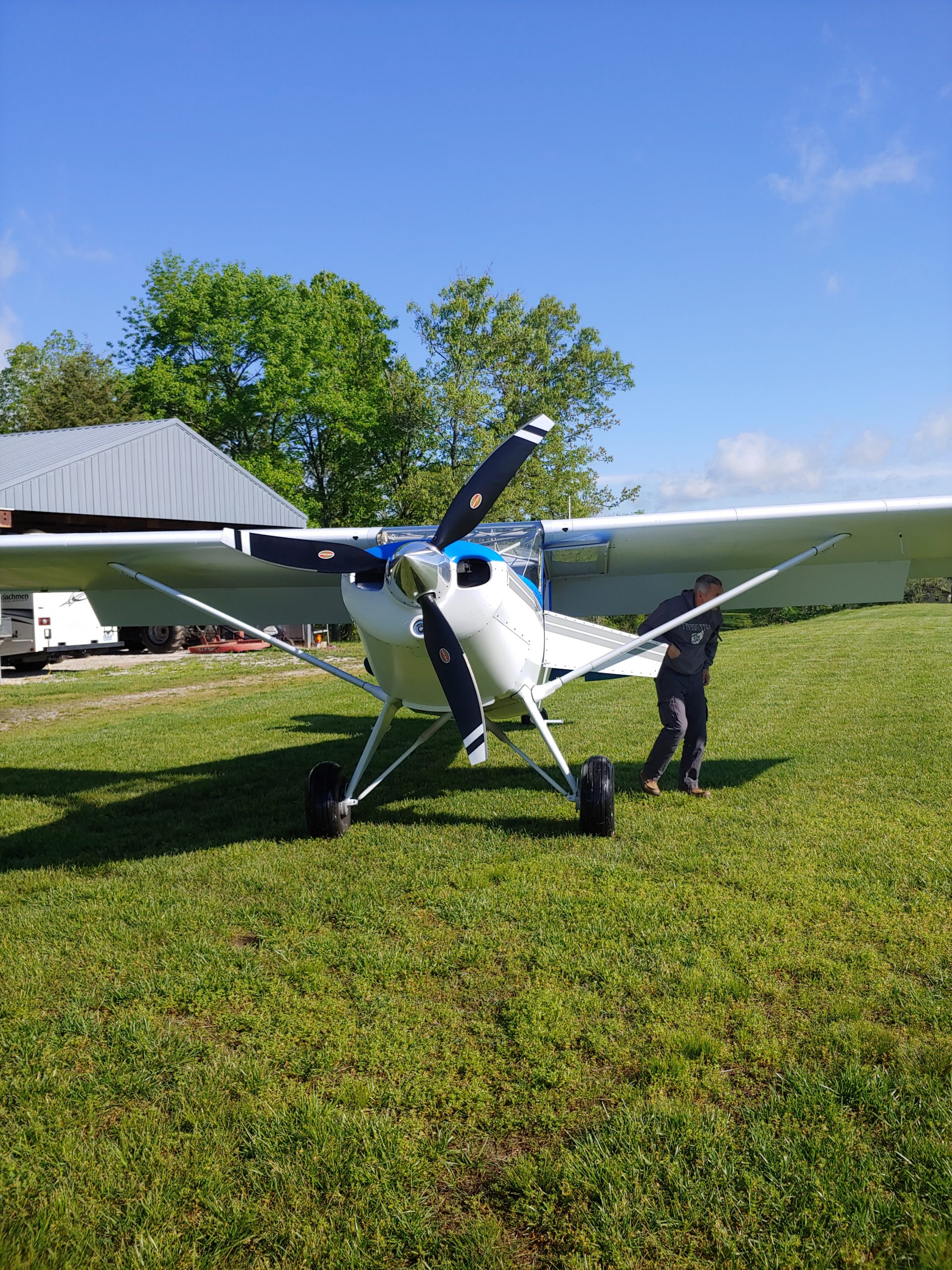
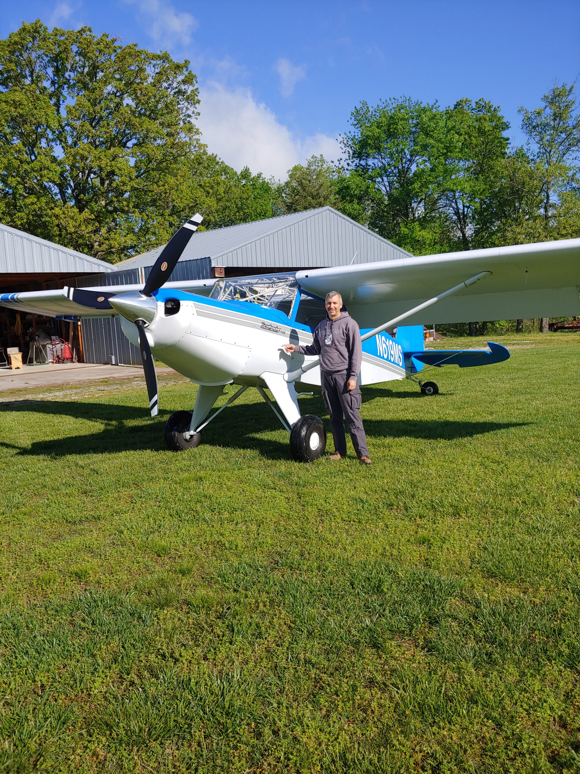
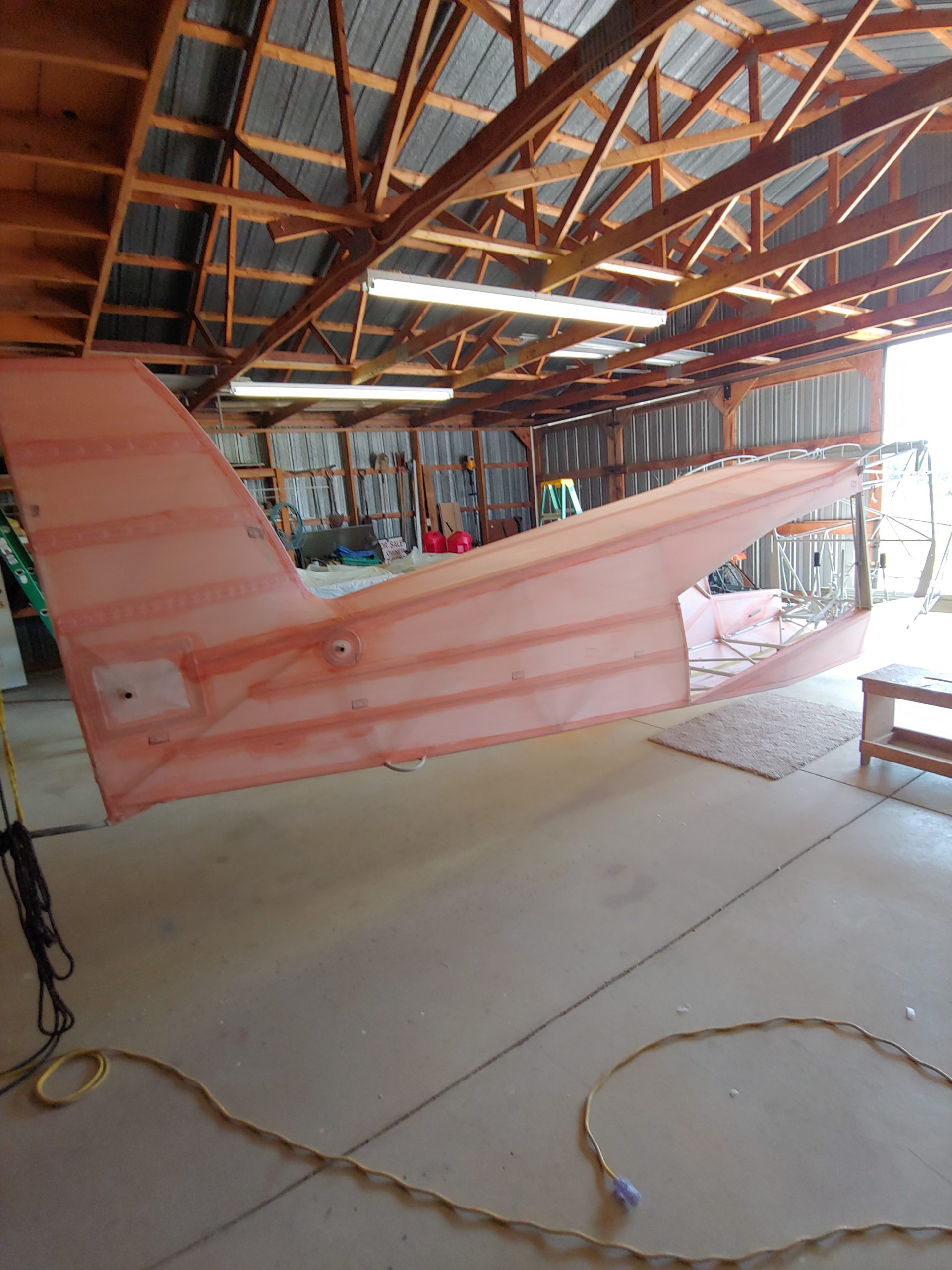
There is another new member of the Bearhawk family! This one is the fifth, and also the largest. This new and highly capable variant has been in the works for several years. It uses the same wings as the Bearhawk 4-Place Model B, but the fuselage, landing gear, and tail pieces are all new designs.
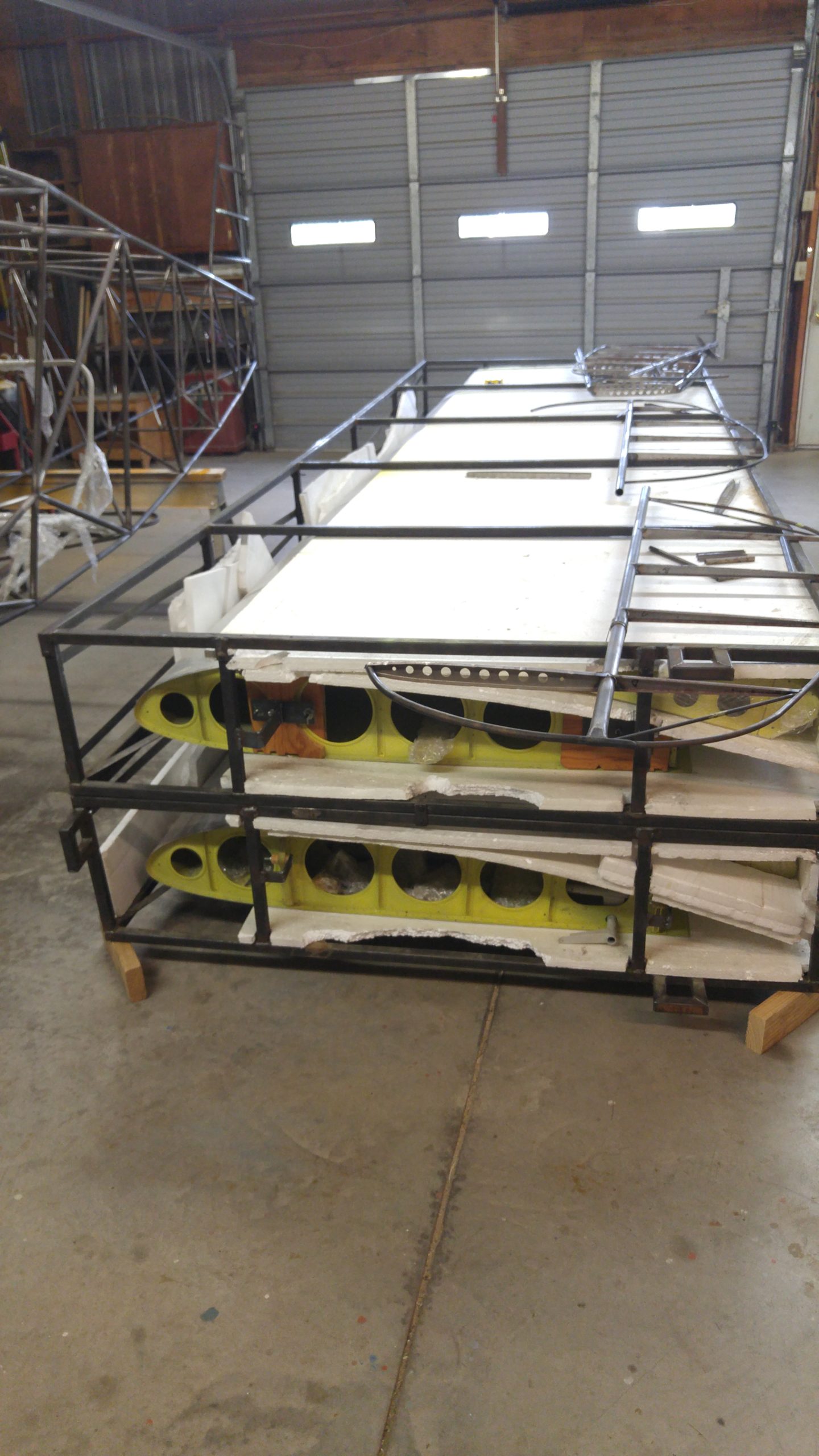
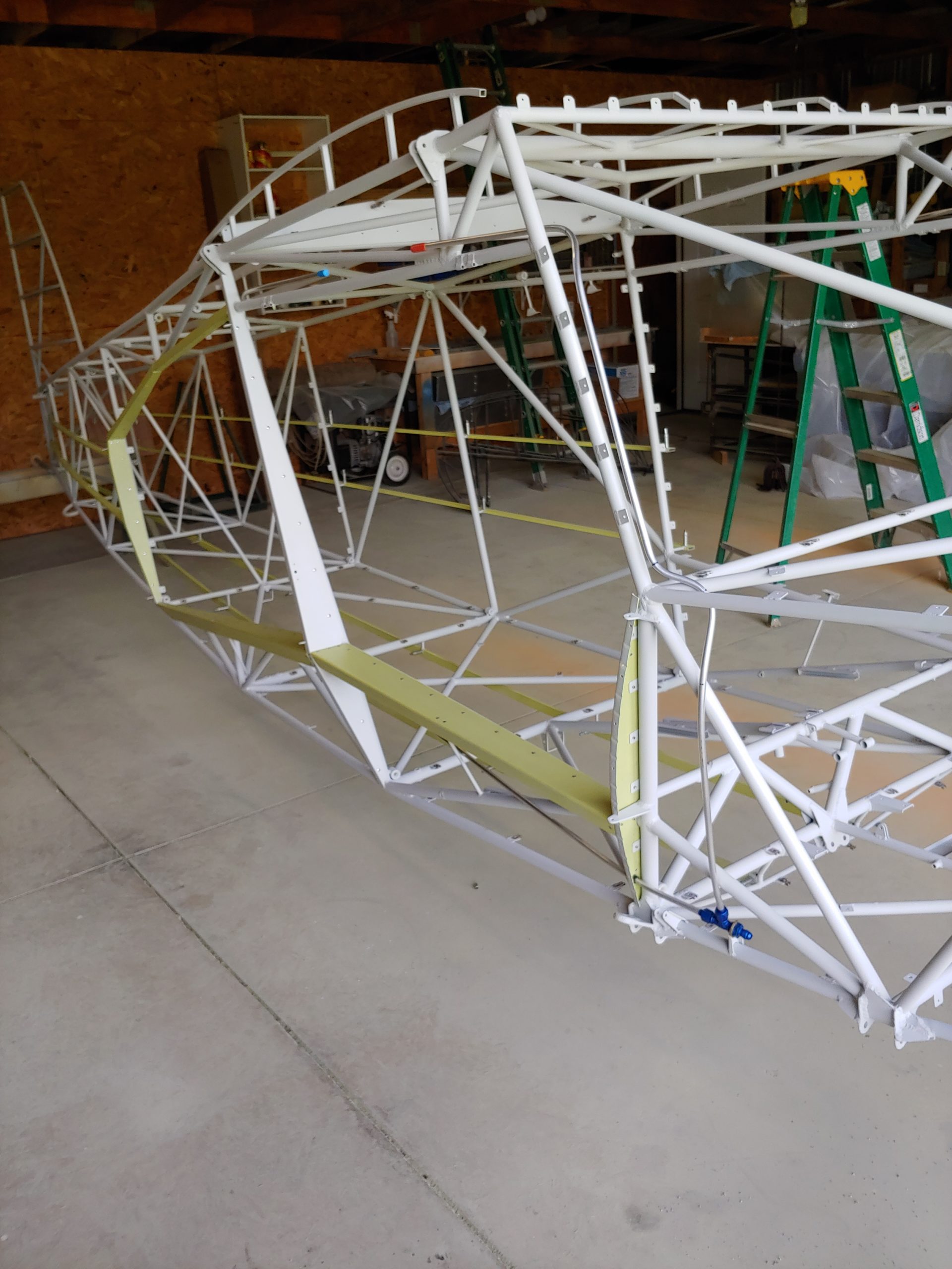
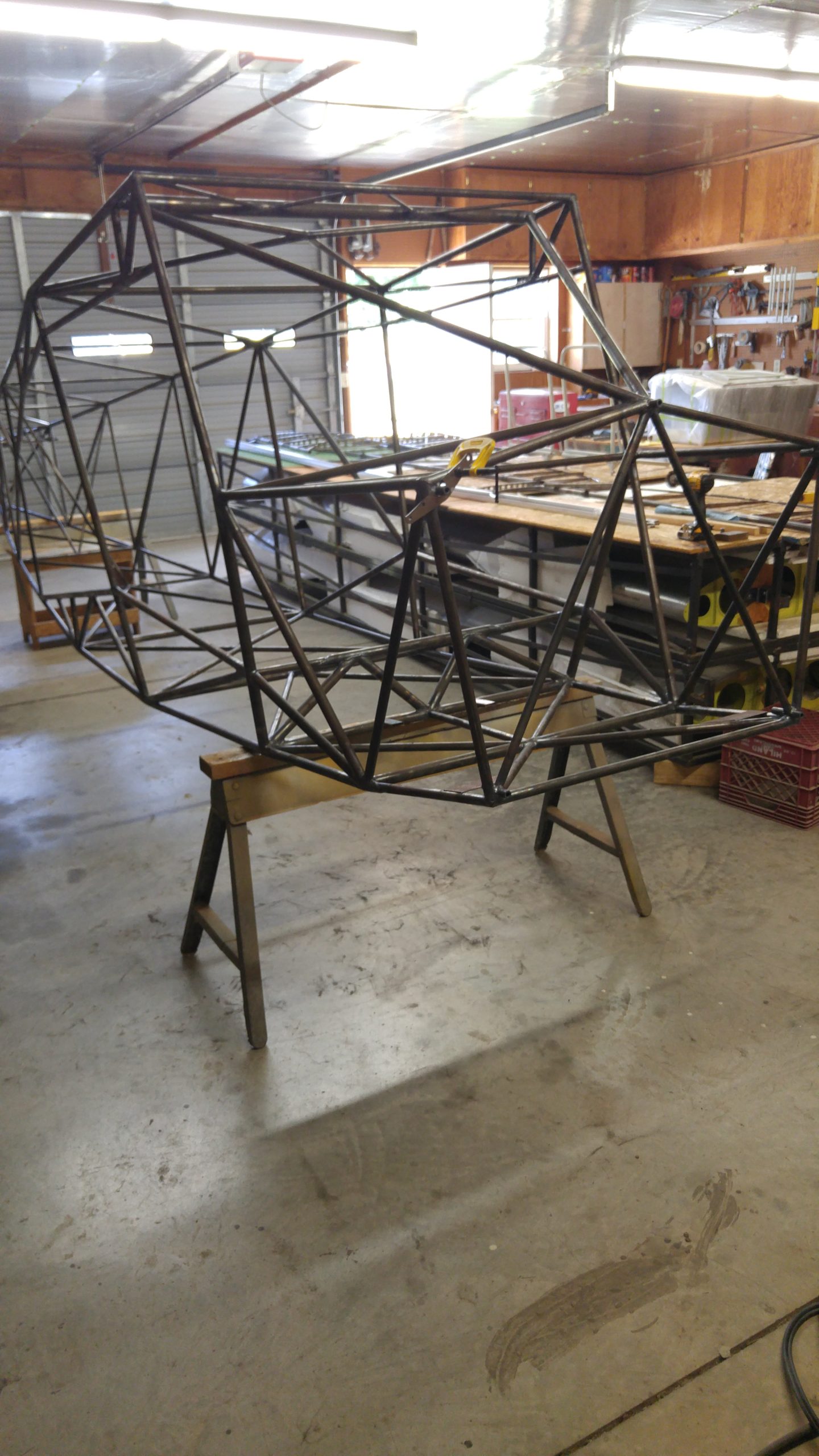
This particular prototype has wings that were built in the Mexico factory by Bearhawk Aircraft, back in the earliest days of the Model B tool-up. The fuselage was originally lofted by Bob’s local friend Jerry Mullins, though Jerry had lost some momentum as the years went by. Skipping ahead to early 2018, serial builder Collin Campbell had finished building his Bearhawk LSA and the vacancy in his shop had him itching for the next project. The Five made its way out to Bolivar, Missouri and just a little more than two years later, here it is.
Collin is perhaps the most experienced Bearhawk builder excluding the factory and Bob Barrows, and his experience shows in the fit and finish of this new prototype. This project required a different mindset and strategy. Collin had a set of plans, but they weren’t yet as tidy and customer-ready as we expect from finished plans. He made frequent contacts with Bob to clarify and adjust as necessary.
When it was finished, Bearhawk Patrol builder and owner Rollie VanDorn from Zanesville, Ohio, came for a visit. Rollie conducted the first flight and the first several hours of flight testing, validating the handling characteristics and initial CG envelope tests. Weather and “day job” constraints conspired to keep Rollie from testing for a little while, so Mark asked if I might be able to go fly a few hours as directed by Bob.
Under normal circumstances, Bob Barrows would be flying these first few hours. In that stage, he wants to be sure that he likes the way the airplane flies. But since he is still recovering from his ankle injuries, he wasn’t up for travelling this time. Instead, Rollie and I were his remote eyes and ears, making multiple phone calls per day to report data and establish the next steps.
When I got there, Bob wanted to validate his positioning of the CG limits, so that he could finalize the first version of the plans. Word had gotten out about the new plane, and Mark had already taken the first two kit orders. Factory tooling was held up waiting for plans, and plans were held up waiting on some test flights.
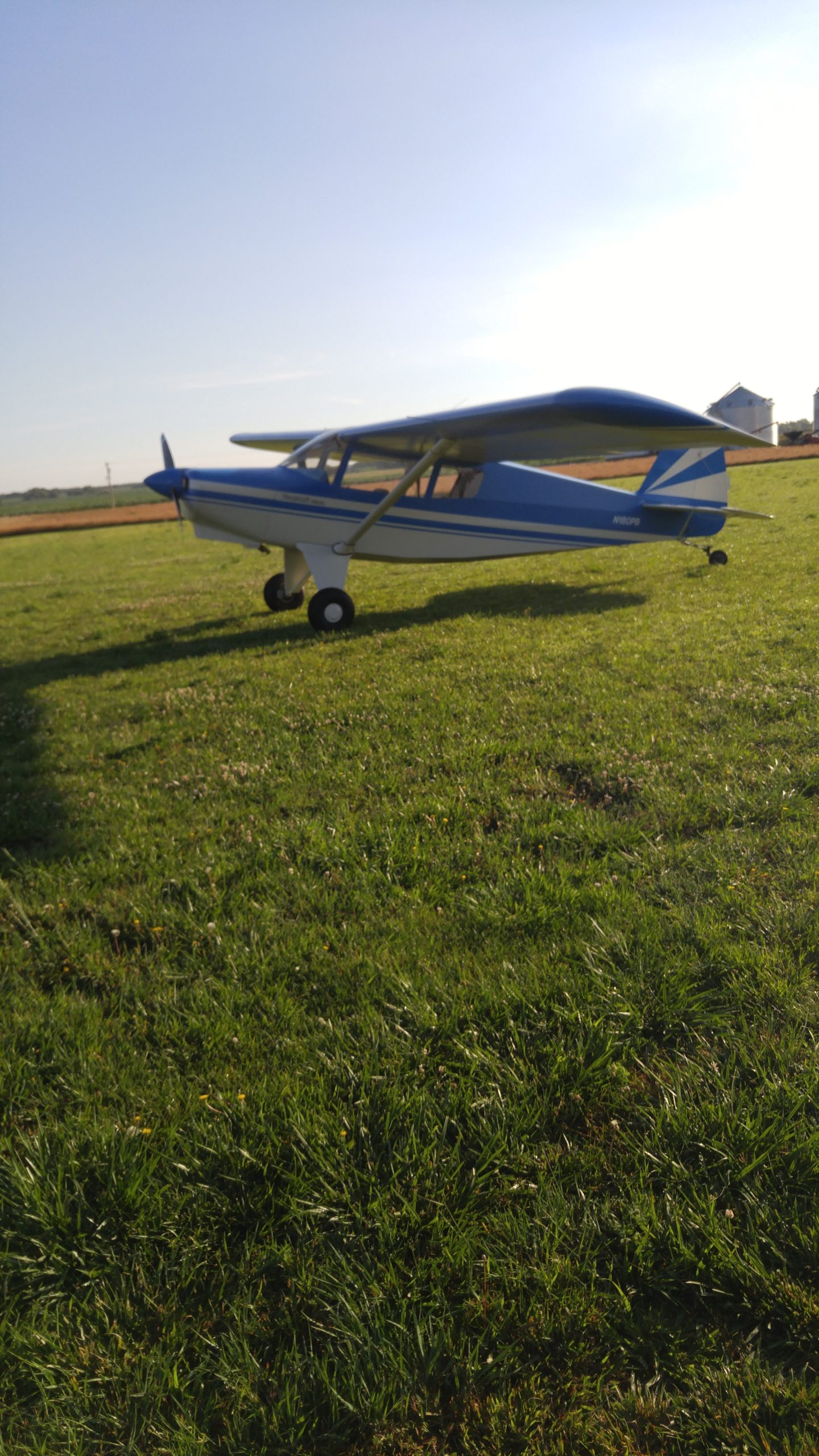
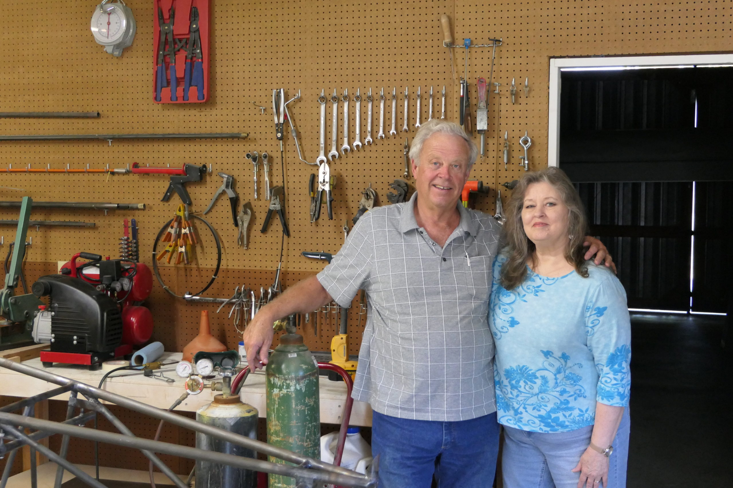 The airplane slept in the hangar at Collin’s house, where he has a short grass runway. Collin and his wife Sarah let me stay at their house in the guest room, which made life quite luxurious. I arrived via airline flight and rental car late on a Sunday night, just around dark. I hadn’t been to Collin’s since June 2018, when I stopped by to interview Collin and get photos for the Kitplanes article about his three Bearhawks. In the photo to the right from that visit, you can see the tail section of the Five, which we snuck unannounced into the magazine.
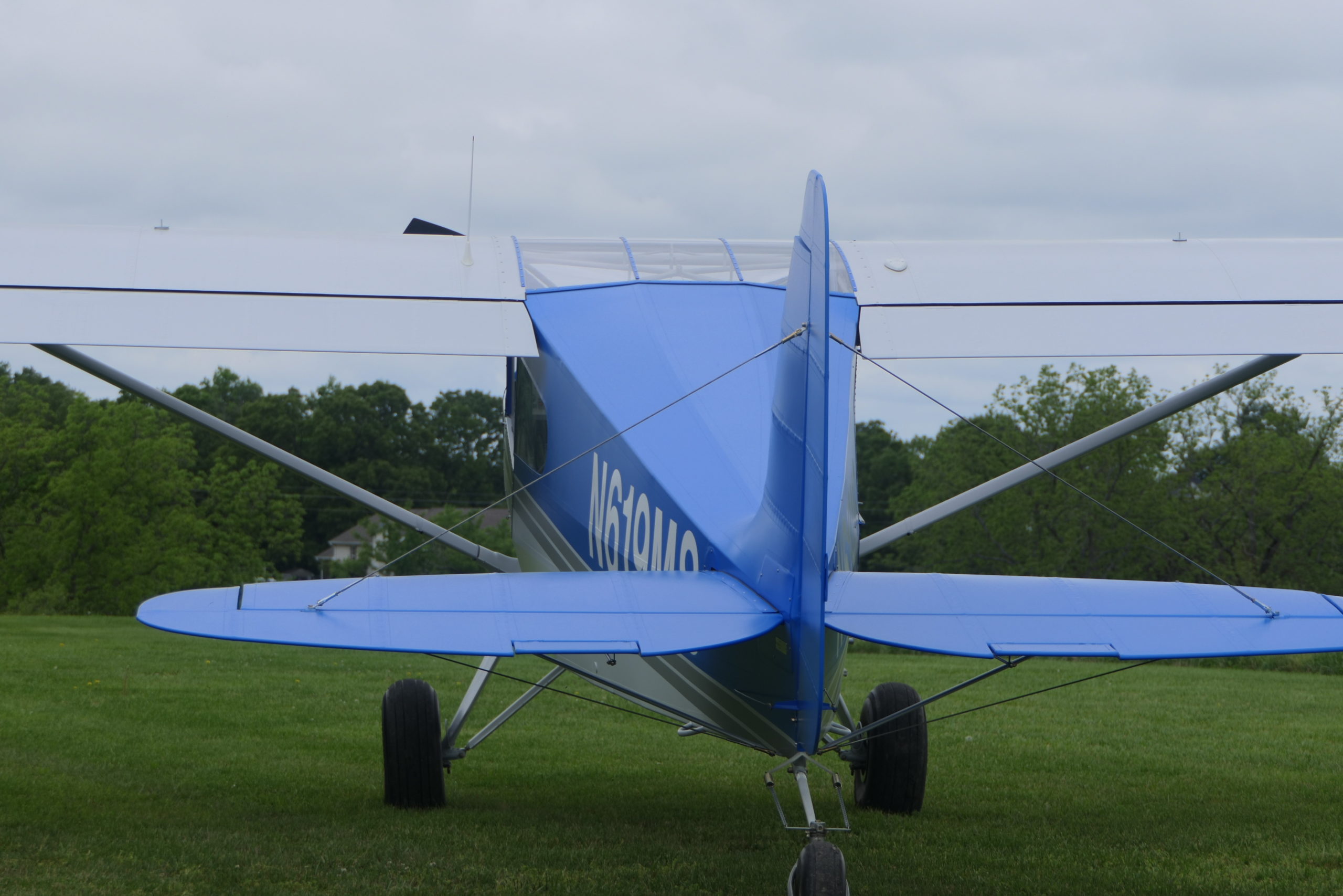
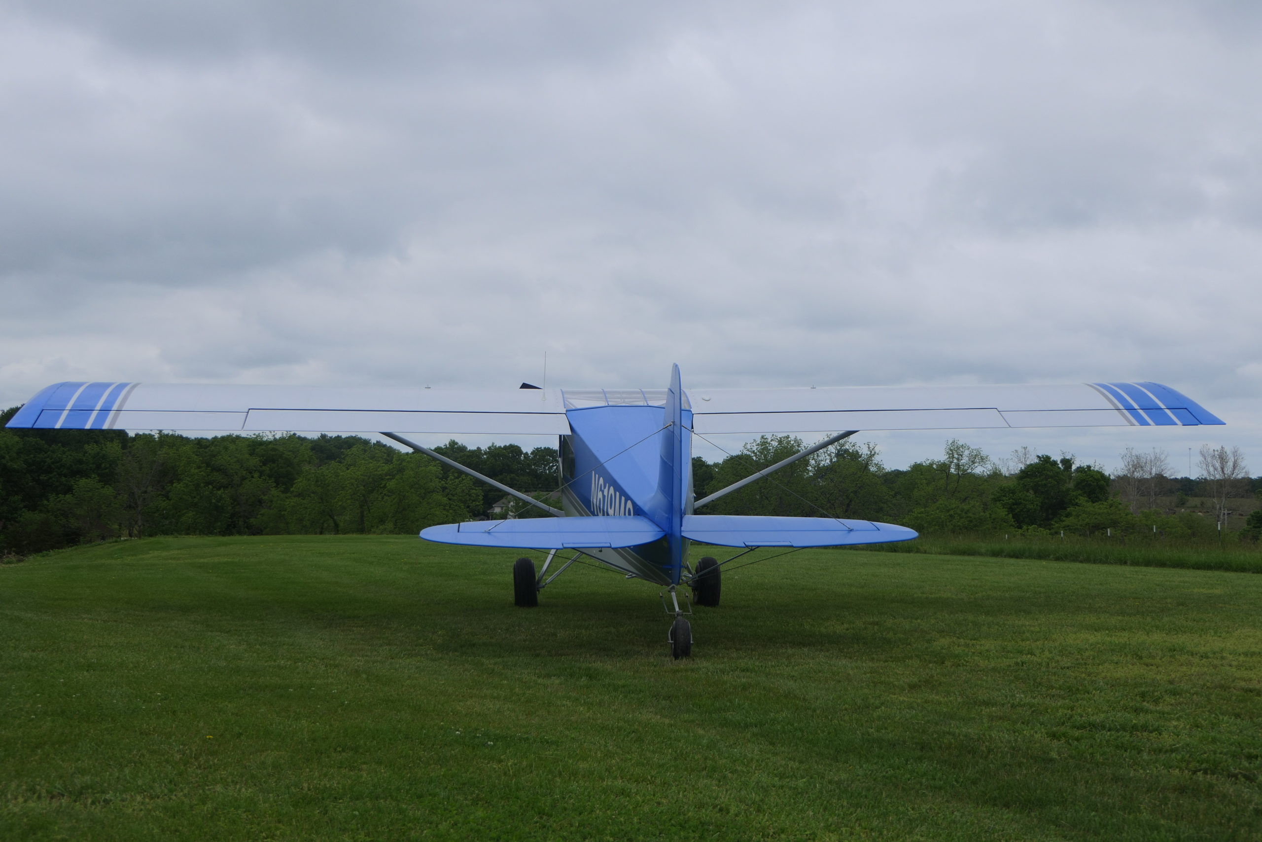
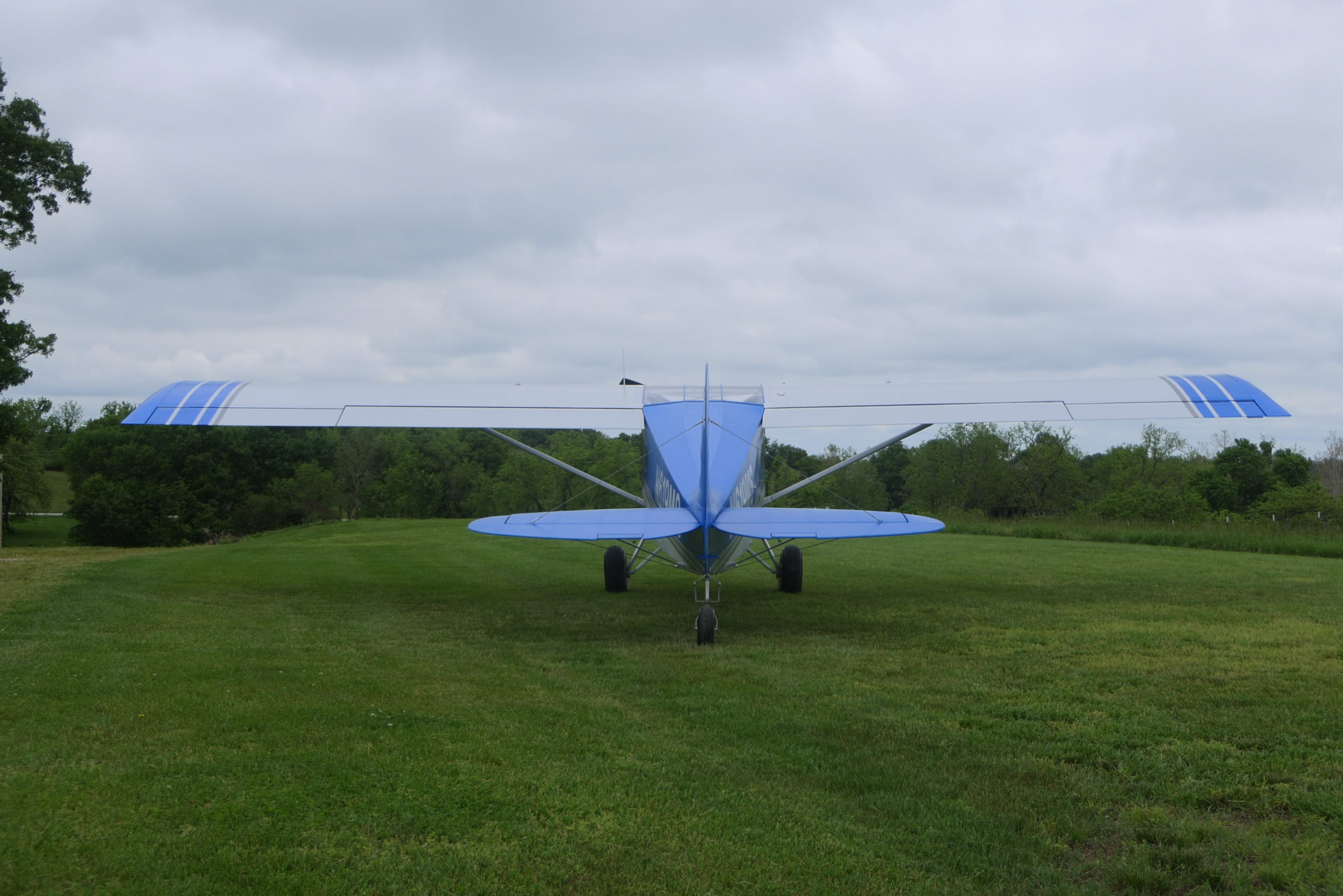
That evening, Collin brought me up to speed on where he and Rollie had left off, and we took a look at the airplane. The most enduring impressions were the build quality and the size. Having crawled around Collin’s three other airplanes to take pictures two years ago, I’ve come to appreciate the “Collin Style”. This includes light colors, clean simplicity, and a soft inviting paint texture that comes from the “Polytone-over EP420” finishing process on all of the metal parts. Something about that is just a little less harsh than the mirror-gloss of Aerothane, or the “orange-peel gloss” of Aerothane that I’ve become accustomed to on the airplane at home. As for size, the cabin is a foot longer, and the fuselage is two feet longer overall. The cabin door is quite obviously wider when looking at the side of the fuselage, and there is an extra few inches of cabin width. The wider fuselage makes the wingspan ever so slightly longer, but that’s not something that shows up in a walkaround. On the other hand, the taller vertical stabilizer, and the thicker and longer span of the horizontal stabilizer and elevator do certainly catch my eye. I’m a little extra-aware of the 4-Place tail span, having executed a wee-hours operation to tow the fuselage to an airport before the first flight, without removing the elevators. There’s no hope of getting away with that on the Five. To someone who hasn’t walked around a few Bearhawks, it might pass as a 4-Place, but I think any builder or observant Bearhawk fan would be able to sense the size difference right away.
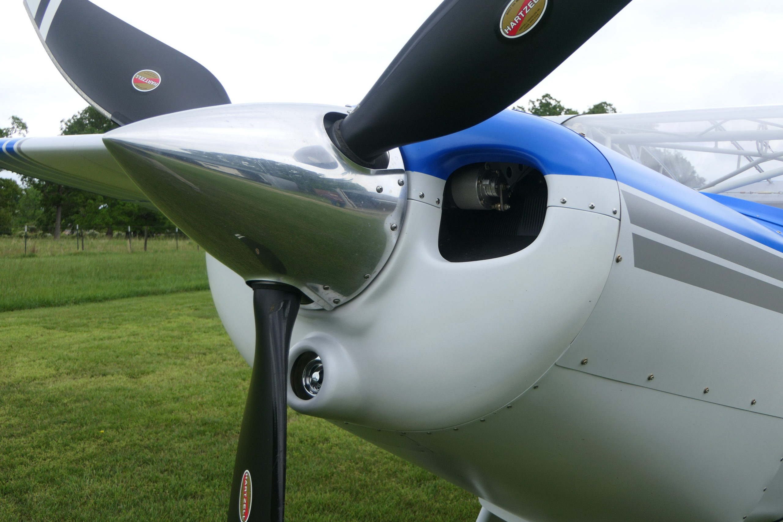
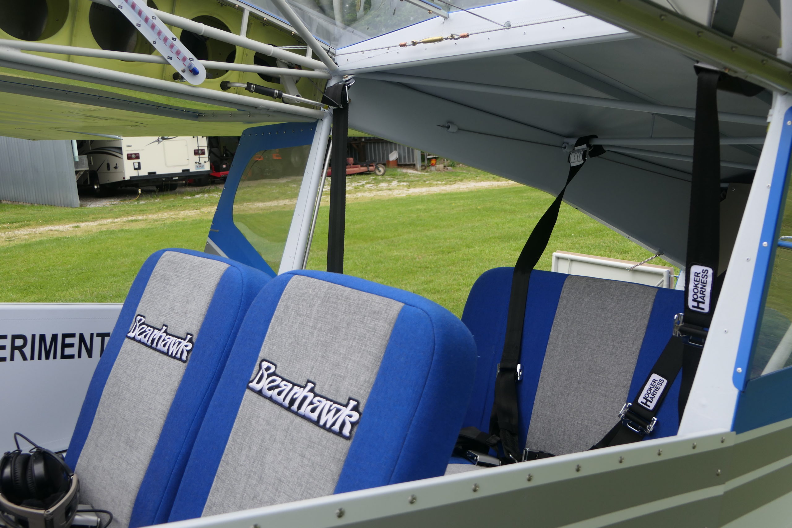
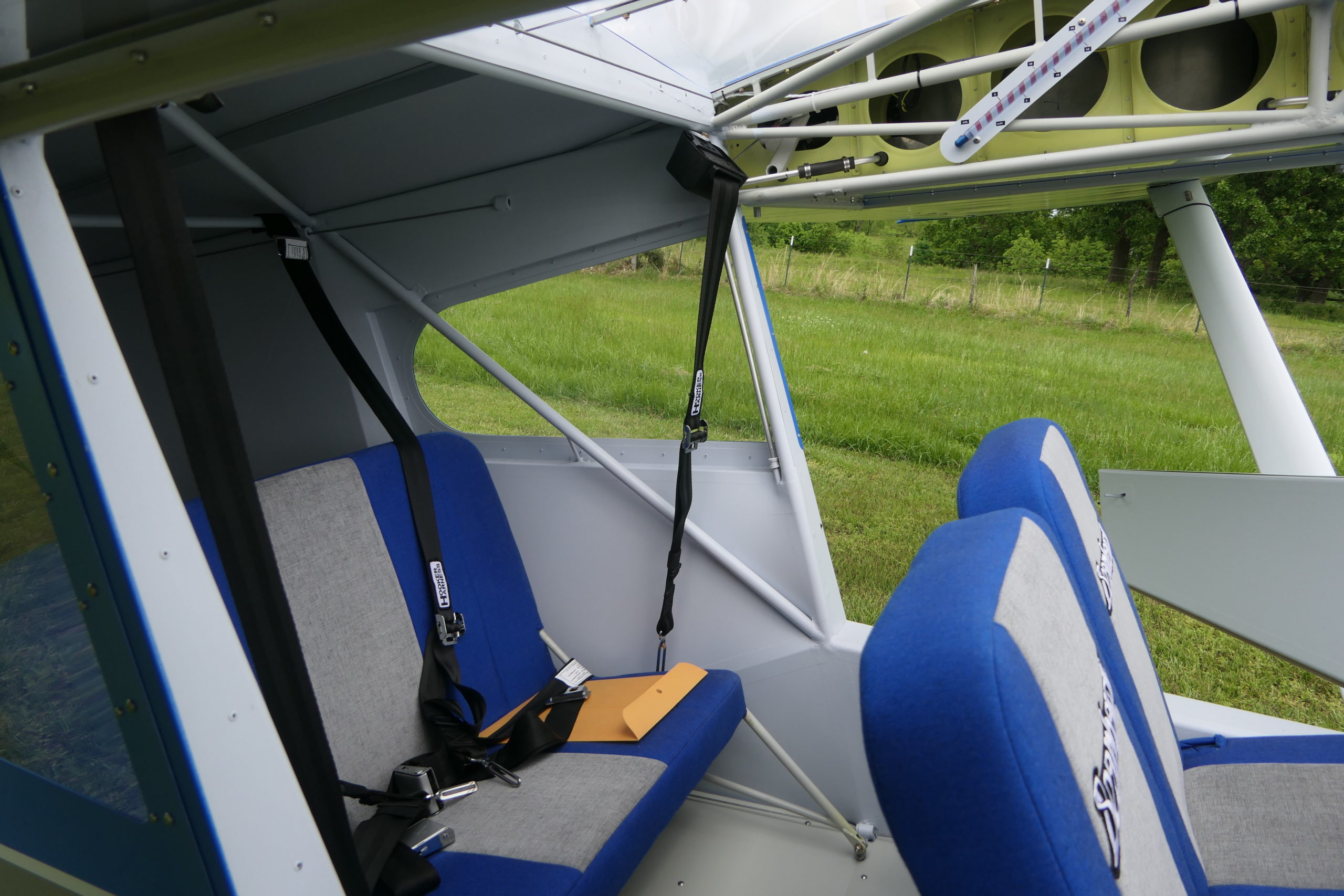
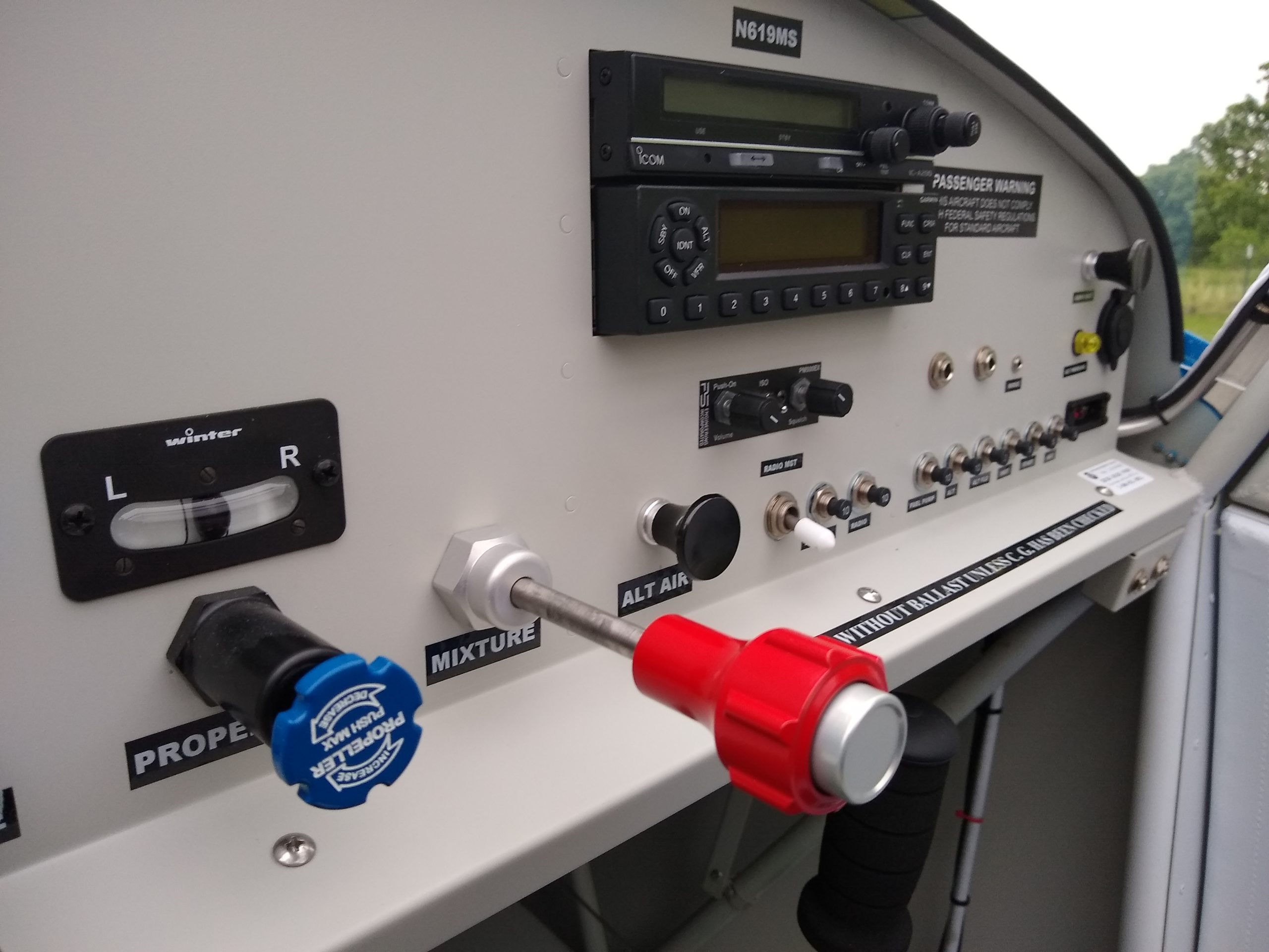
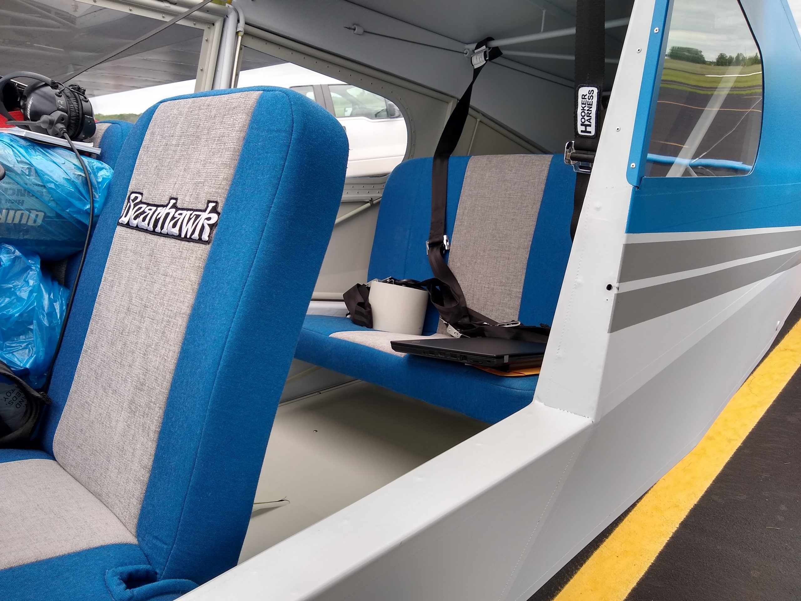
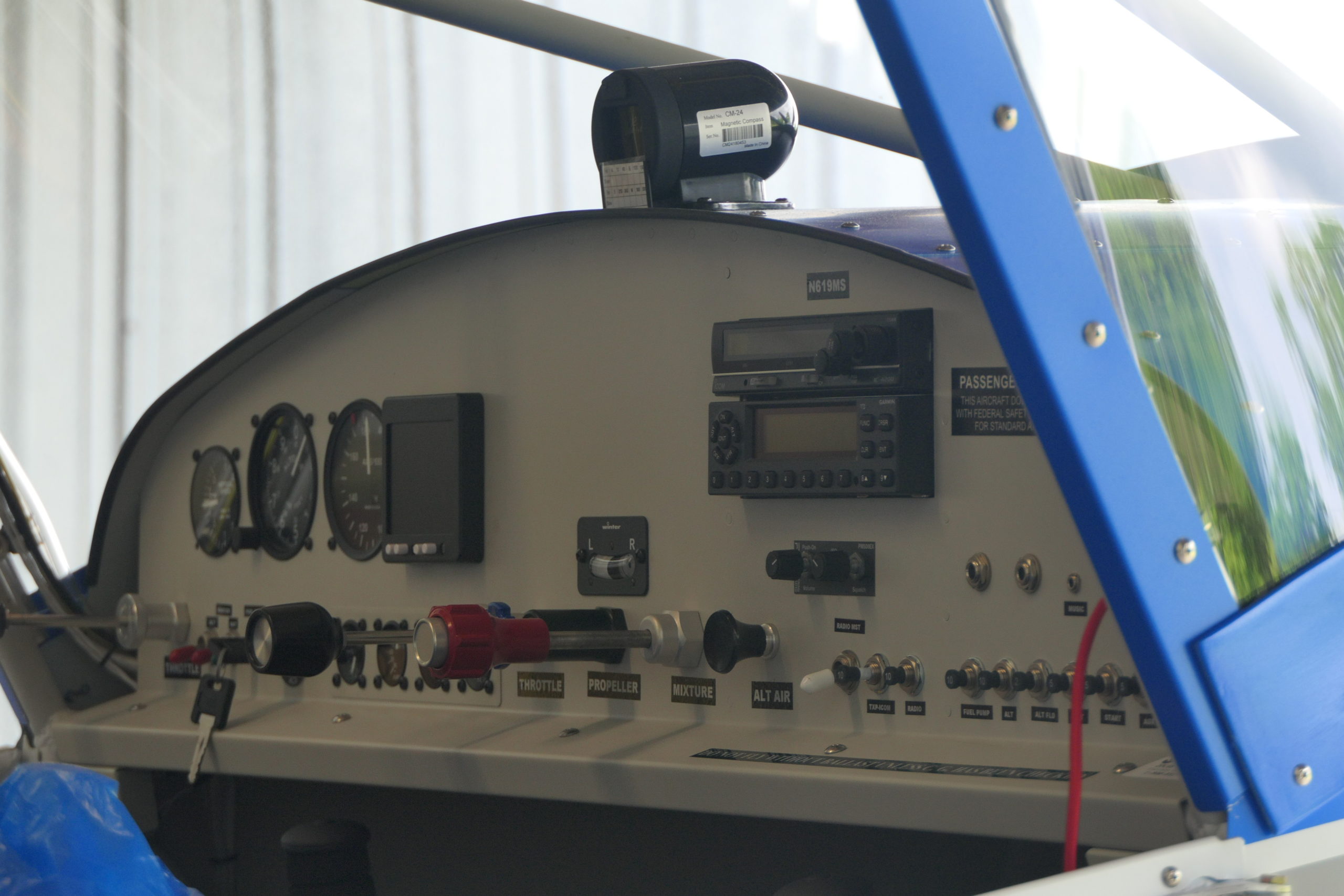
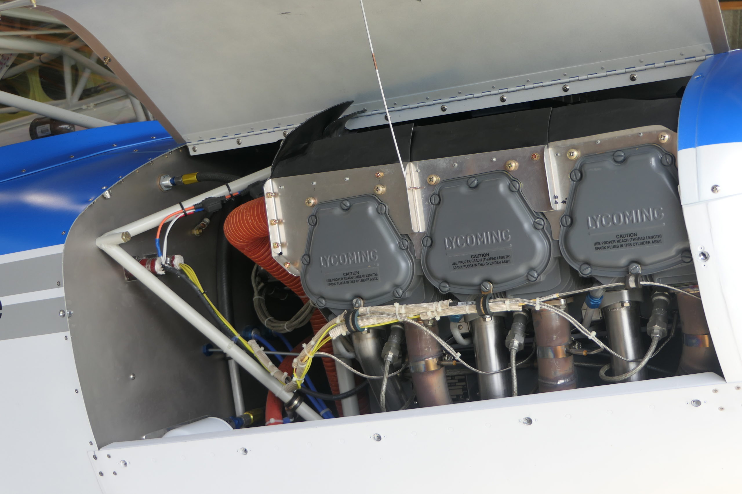
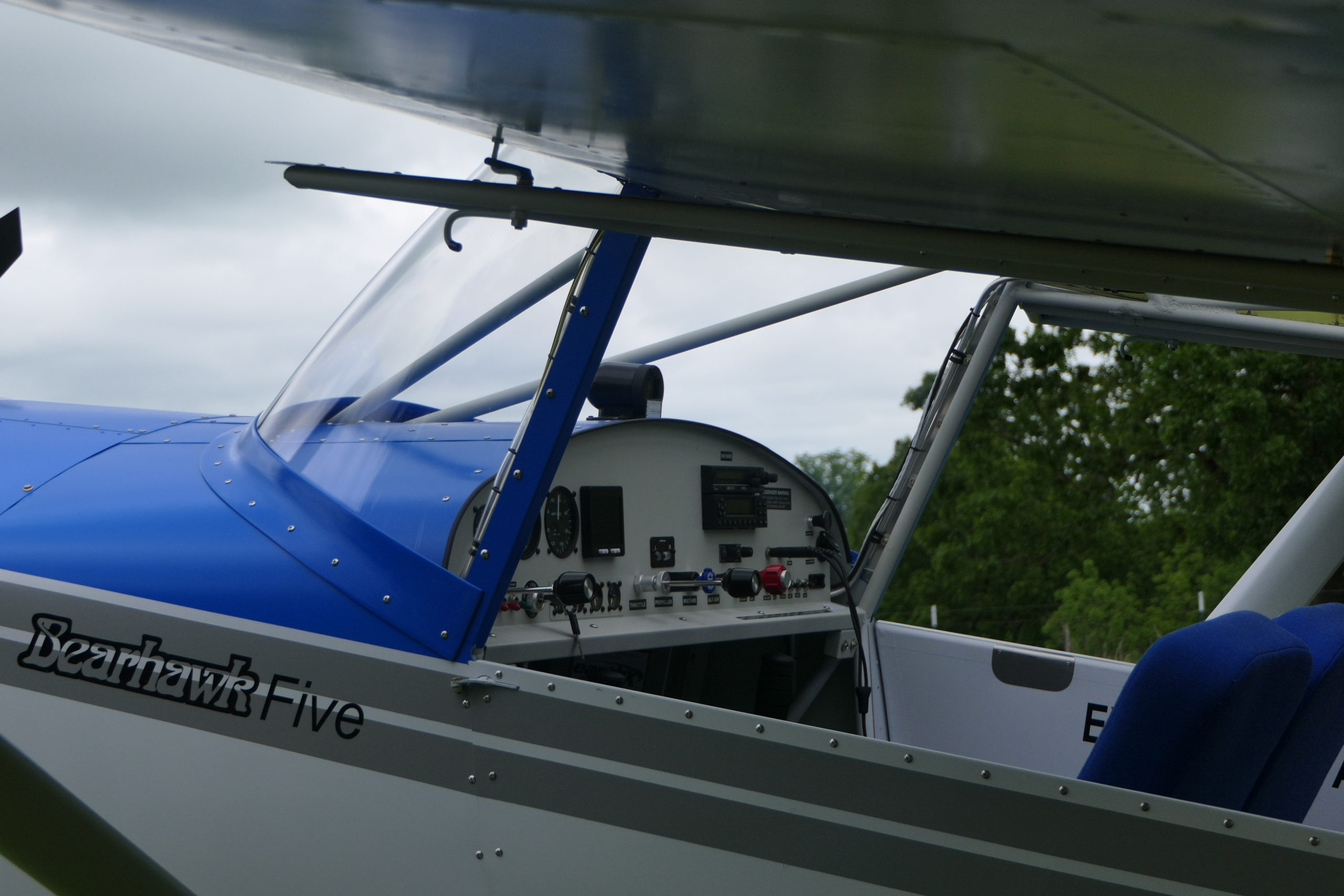
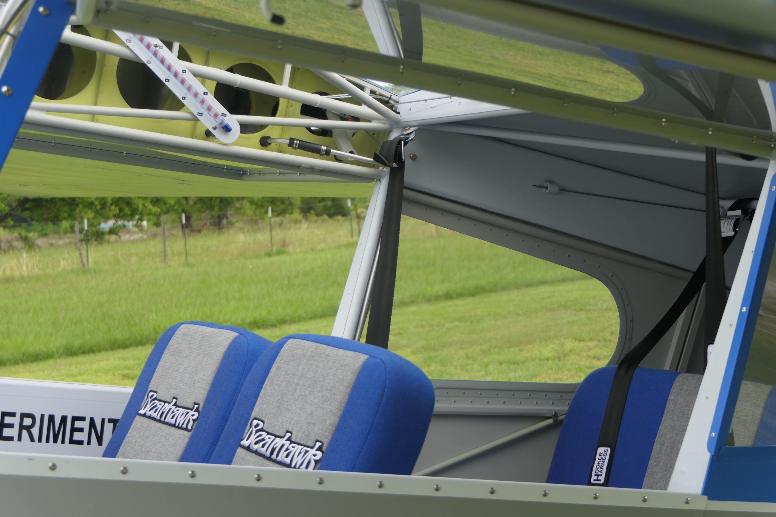
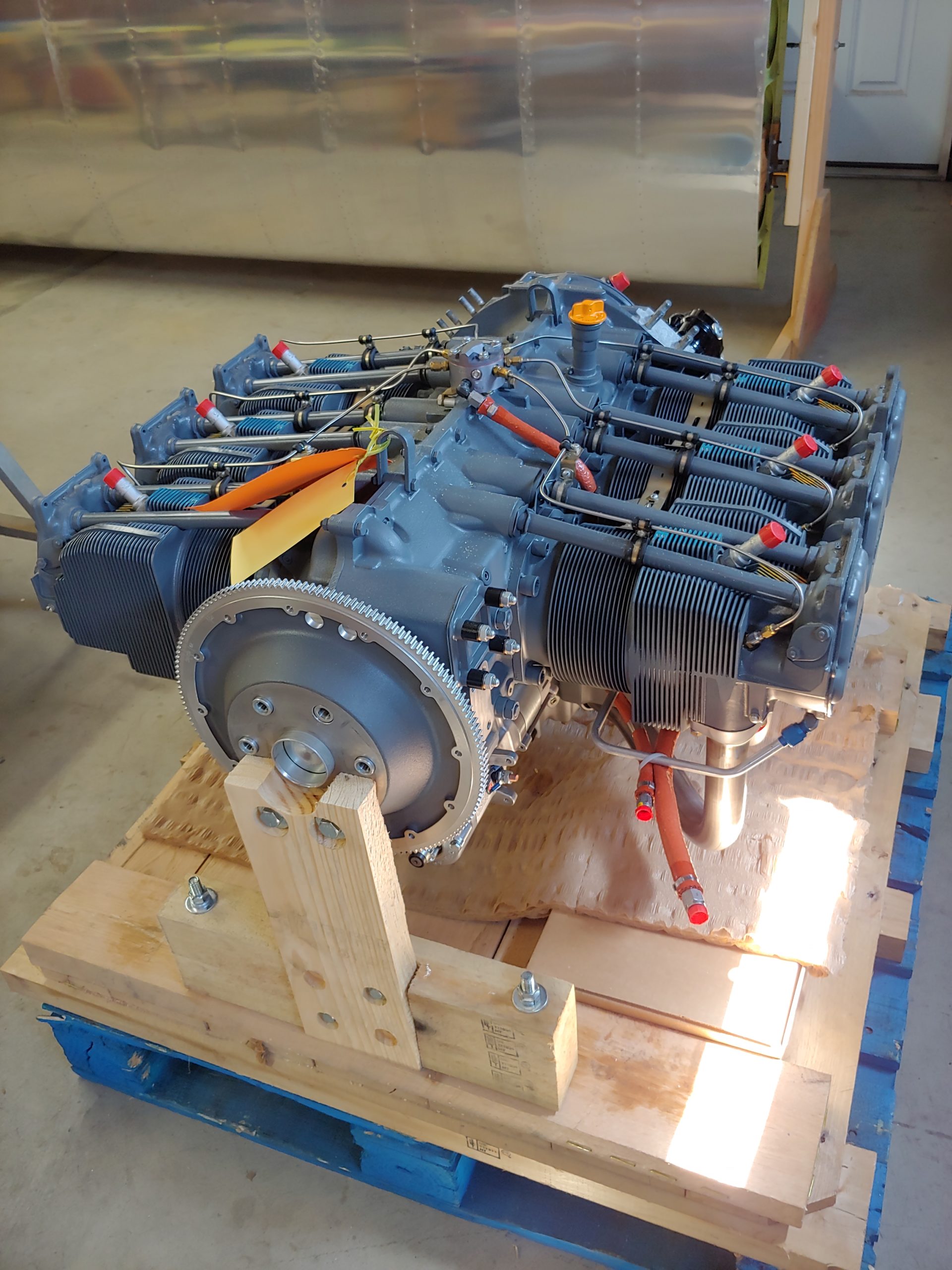
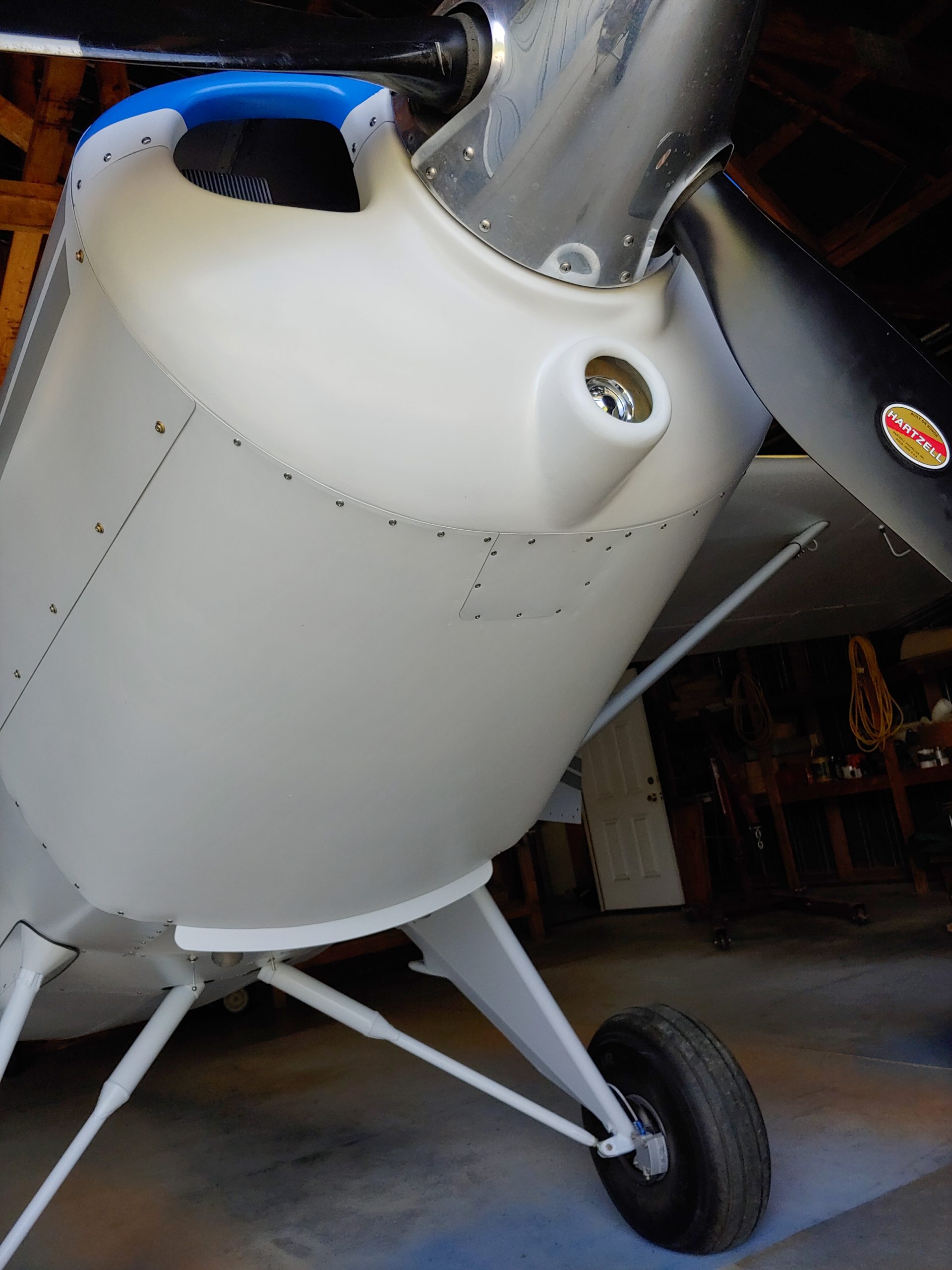
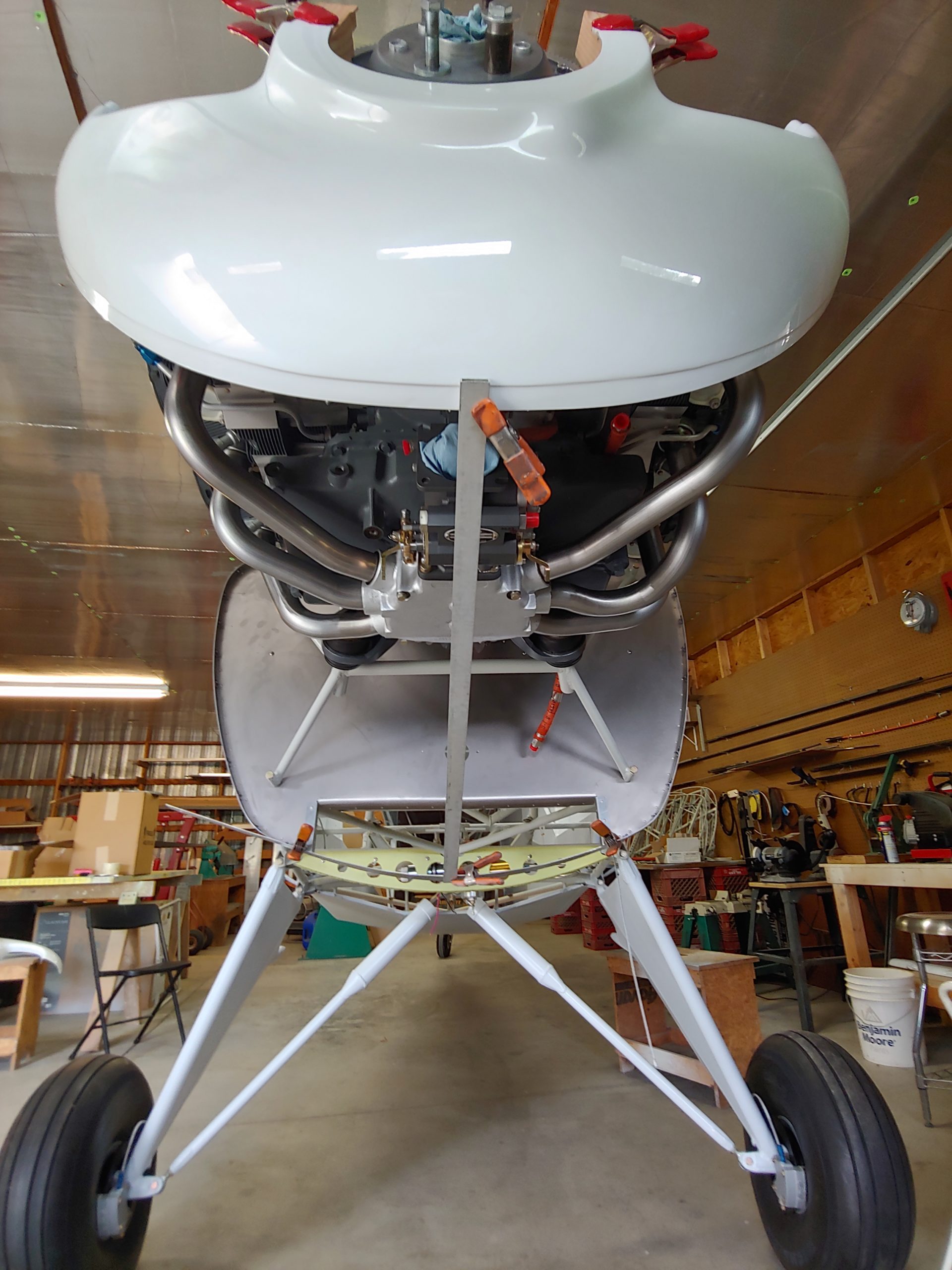
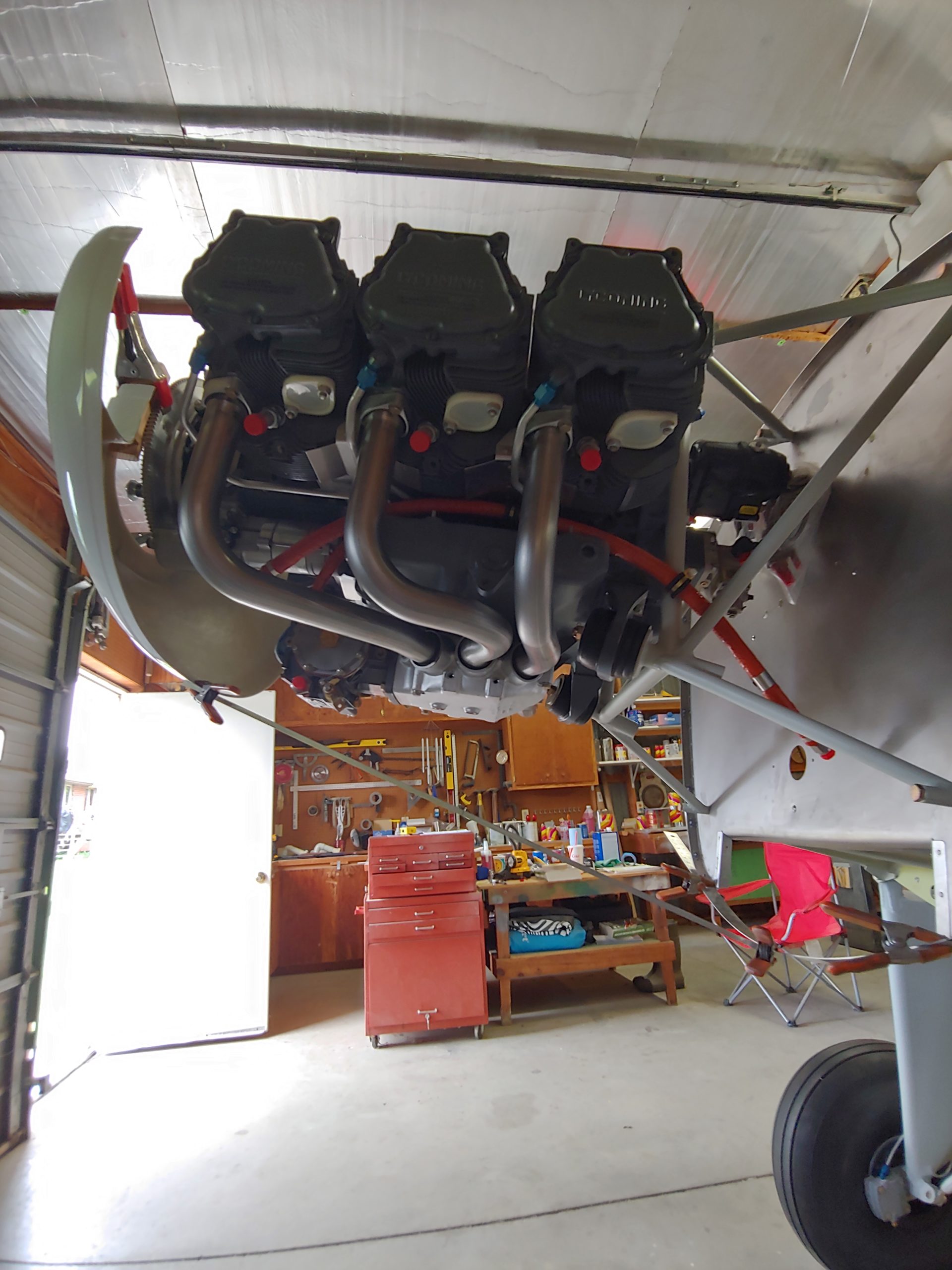
Collin built and configured this airplane with the expectation that it would eventually become part of Mark Goldberg’s company demo fleet, so it incorporates several of Mark’s equipment preferences. The panel is minimal VFR to keep down the weight and the distractions. The interior is configured with four seats, though of course there is enough room in the cabin for a third row. If building it to be a 6-seater, the second row seat could come forward a little to sacrifice some of its cavernous legroom, which would be nice for the third row occupants. As it is currently configured, this plane is a very spacious 4-seater. Mark also selected the engine, which is a beastly Lycoming IO-580 rated at 315 horsepower. The three-blade Hartzell Trailblazer prop is the same one that I’ve flown on Mark’s Bearhawk 4-Place, and the thrust is fantastic. The parallel-valve O-540 is another less thirsty option that should still produce a nice flying Bearhawk Five, with its mere 240hp.
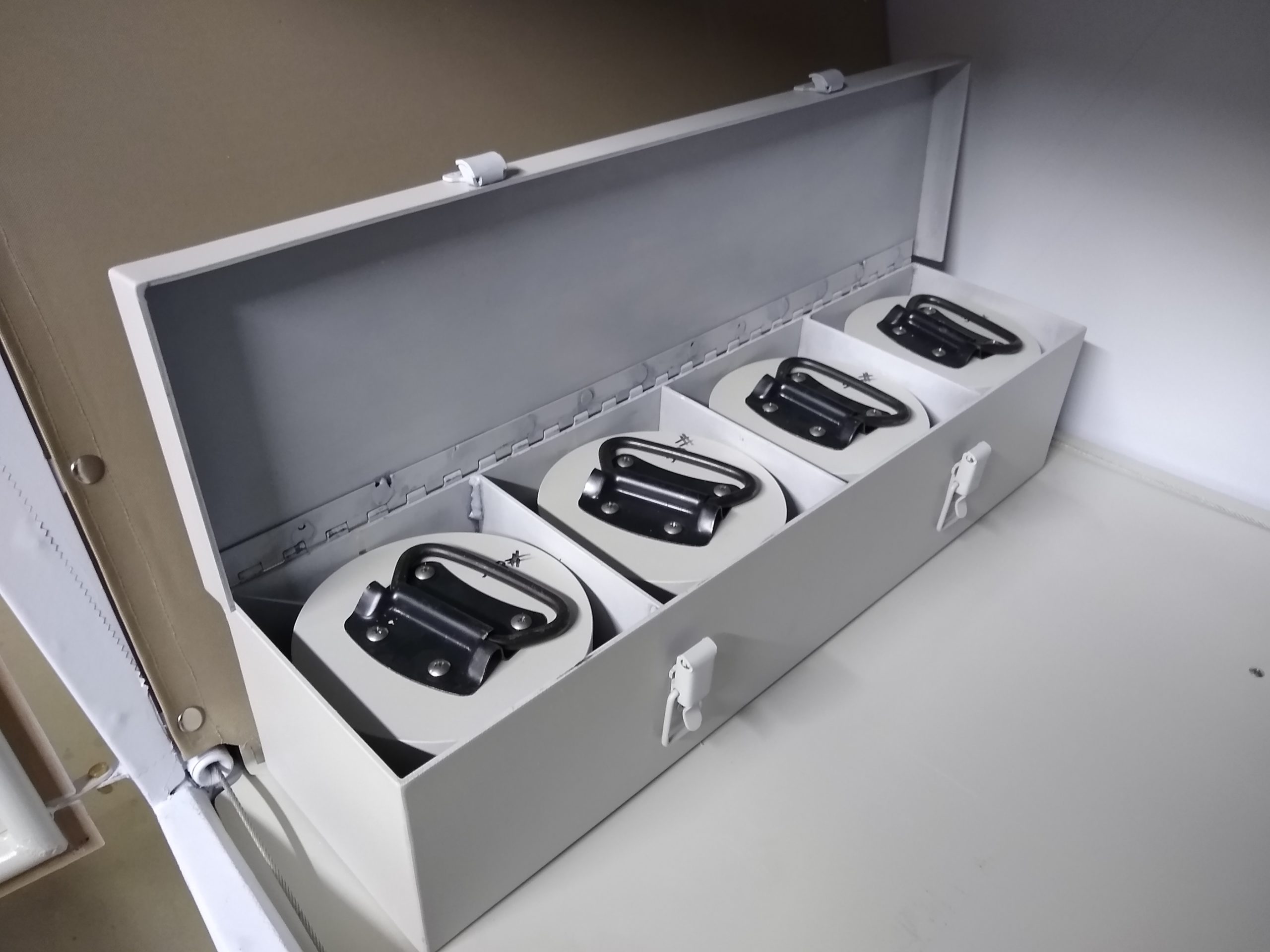
On the first day of flying, we were able to complete Bob’s tasks for verifying the forward CG limit. This involved incrementally moving the CG forward, with a flight after each change to verify that there was still adequate flare authority in the landing. Even at our forward-most configuration, there was plenty of elevator authority left for the flare, without needing to add power. As we moved the CG forward, the neutral elevator position became increasingly nose-up, until it reached around 4 inches at the counterbalance. The Five, along with newer Four-Place kits have 35 degrees of nose-up elevator travel. The increased travel, increased tail size, and airfoil-shaped profile all helped us reach a more favorable forward limit. Since this the first prototype, there will be some differences in the serial kits. The prototype has a ballast box in the back of the baggage area, and it isn’t yet clear whether a similar box will be required in production kits. Bob designed the heavy-duty steel box so that four separate 38-pound weights can be added or removed. Each weight is a piece of round steel bar, which you would definitely not want to drop on your toe, or anything else. Thankfully there is a sturdy handle on top of each one. Bob is always good at designing lightweight structures, but in the case of a ballast box, the design goal changes since adding weight is the goal. I’m happy to attest that he’s quite capable of designing heavy things also.
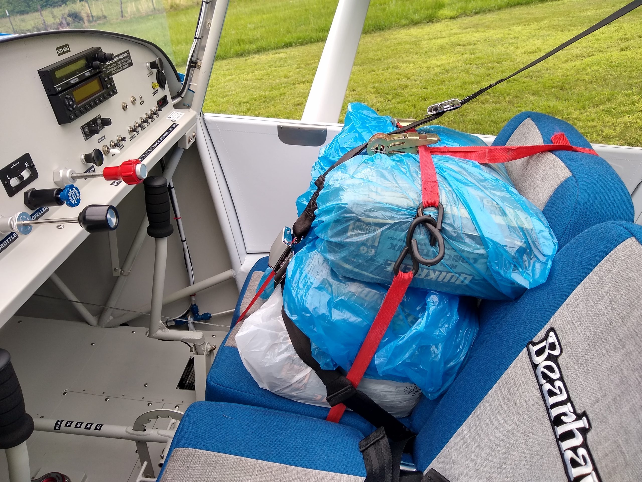
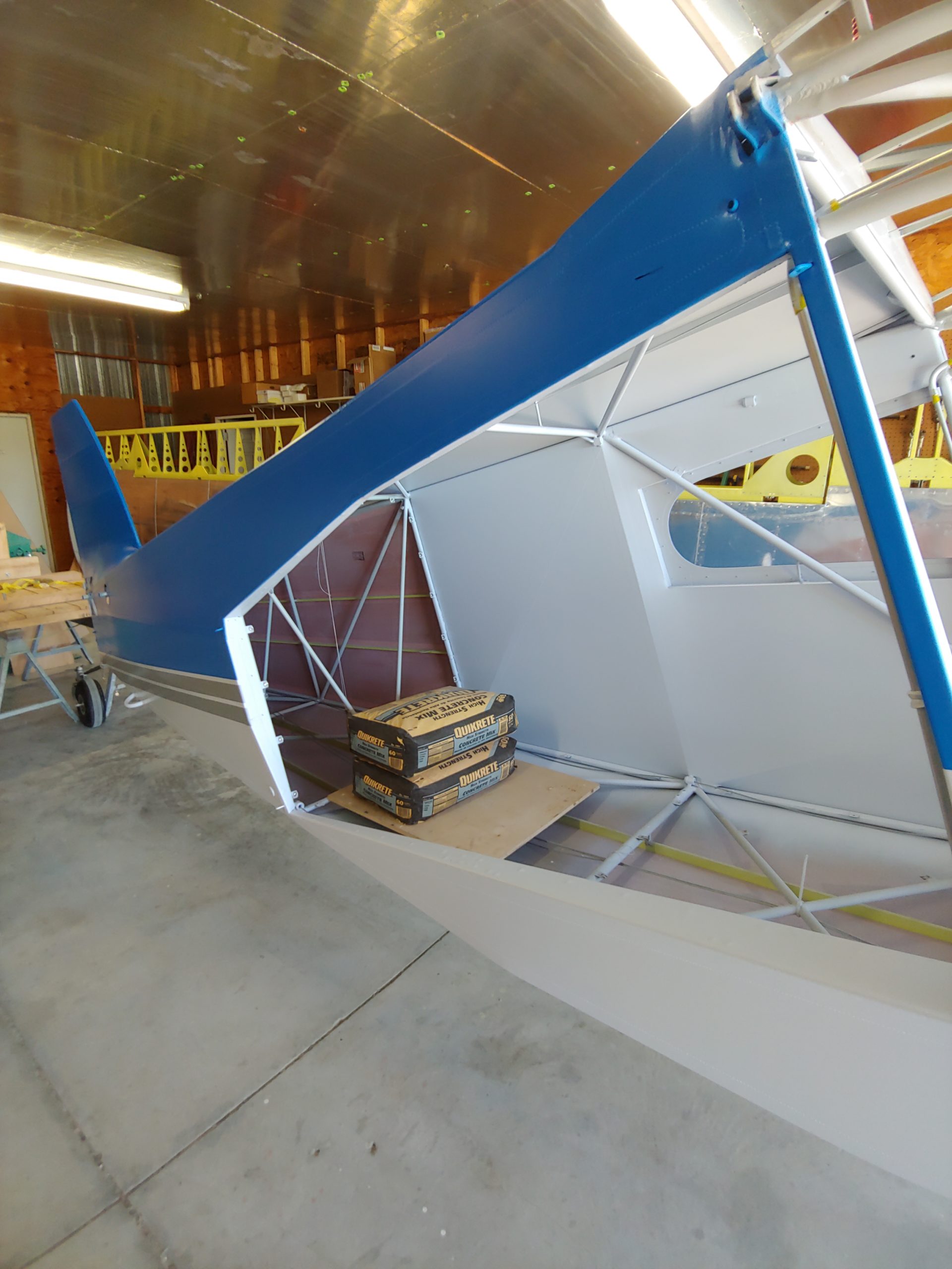
On the second day of flying we tested both the maximum gross weight, and the aft CG. This required ballast, so I started by ballasting myself with a hardy breakfast. I needed it, because with an empty weight of 1512 and a target flight test weight of 3000 pounds, there was a serious gap to fill. We used concrete mix bags, sand and gravel bags, and fuel to gradually work our way up to 3000 pounds and the
rear-most CG. While we didn’t get very scientific with the takeoff and landing roll measurements, just watching the runway lights and markings showed a takeoff roll of around 500 feet at the heaviest weight, with a climb rate of 1000 feet per minute and a fuel burn of 30 gallons per hour.
The cruise performance was very good, even at much more favorable engine settings. When I configured the engine for the same 8 GPH fuel burn that I would expect to use on my O-360-powered 4-Place, the Five yielded the same 115 mph cruise speed. This tells me that any performance penalties of the heavier weight are overshadowed by the drag improvements absent from my Model A. We find that most of Bob’s airplanes don’t suffer much of a cruise speed reduction at higher weights. At an economy power setting more fitting for this engine of 12.3 GPH, the IAS was 141 mph, CAS was 131, and TAS was 150 mph. The calculated engine output was 56% power, at 2400 RPM and full throttle, lean of peak. This is how I would have set up the engine if I was going to go somewhere with it. But just for giggles, advancing the mixture level upped the fuel flow to 17 GPH, which the little JPI calculated to be 70% power. This got an extra 13 mph on the true airspeed, but my wallet was trembling even though I wasn’t paying for the fuel. Some sort of pocket solidarity going on there. This particular plane has 50 gallons of fuel, which means there are real range implications to flying like that for long. Collin placarded these tanks at 25 gallons each, leaving a small air gap at the top to limit overboard venting. Totally filling them up to the tippy-top, they might hold a little more than 50, but might not hold it for long if flying even slightly uncoordinated.
There are much more detailed accounts of the test flights at https://bearhawkforums.com in the new channel that we created just for the Bearhawk Five. The biggest takeaway for me is that Bob has created a fantastic new addition to the lineup. I was first attracted to the Bearhawk because it had four seats, and so few homebuilts do. The payload and cabin size of the Five will open up a broader market and make available an airplane with very few peers. It was quite a privilege to get some time in the airplane, and I hope many more of you will get to experience it once it’s out of the Phase 1 period and out and about. There is much more testing and proving to do, taking the airplane out to its natural habitat and really showing what it is capable of.
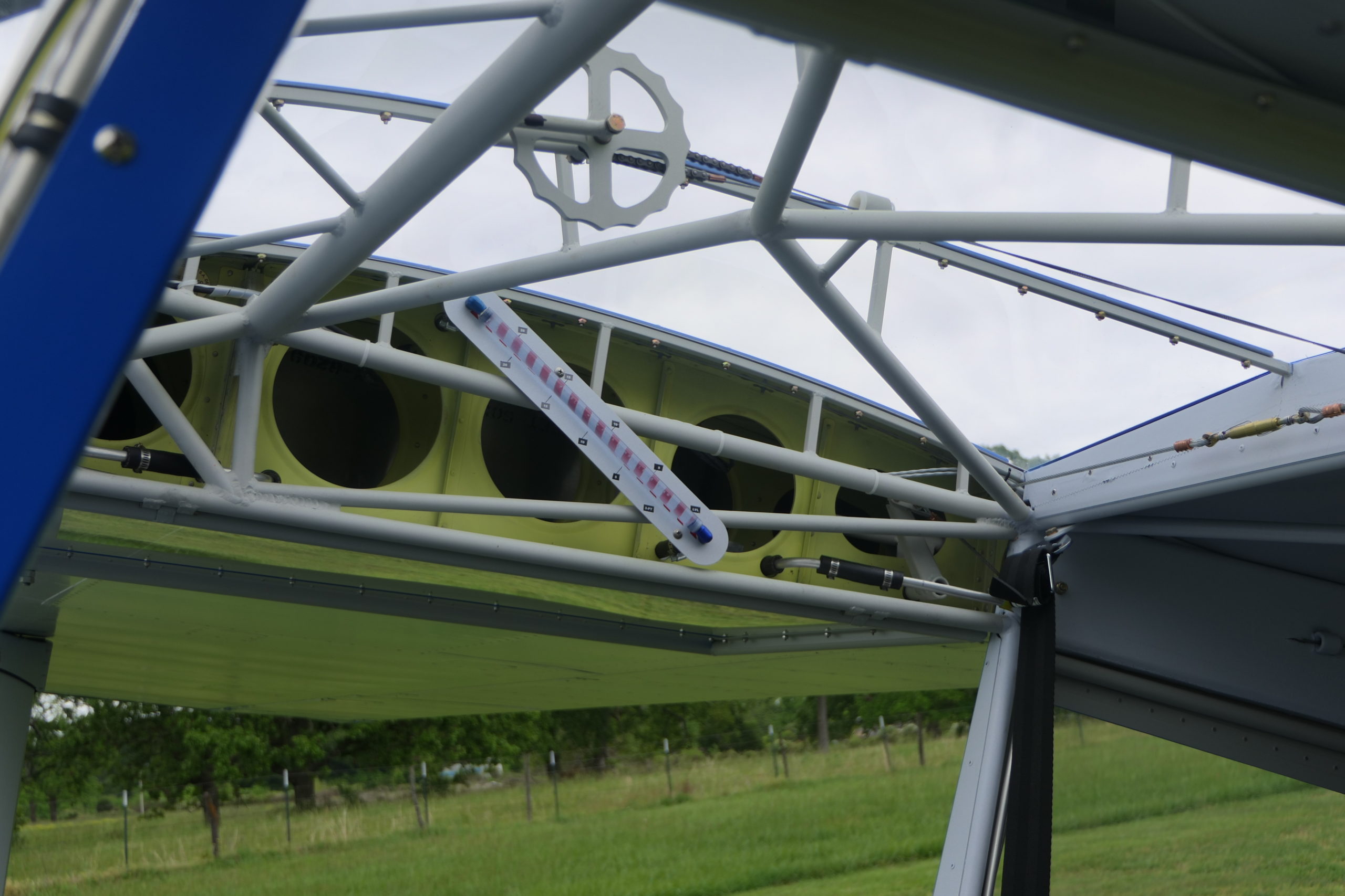
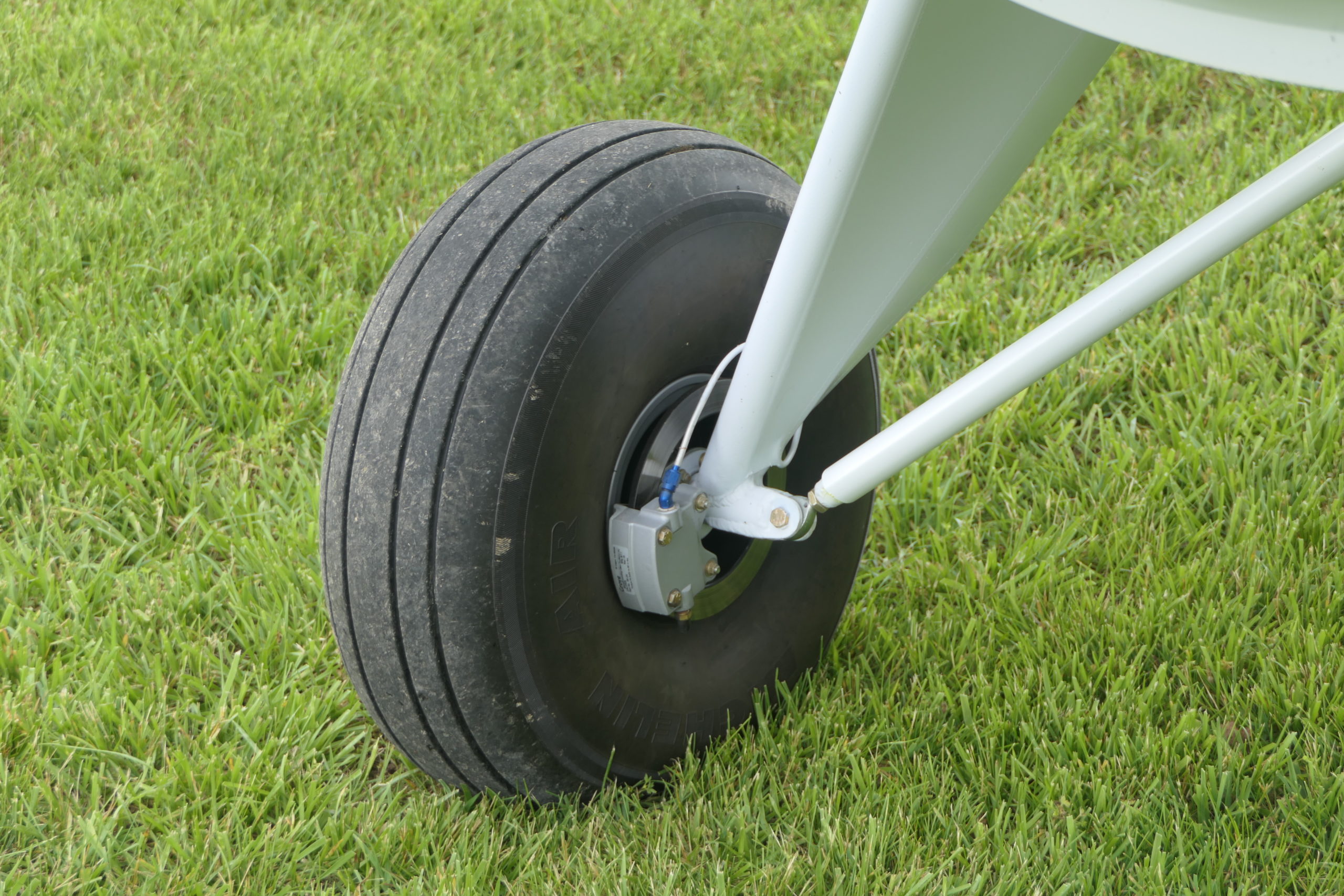
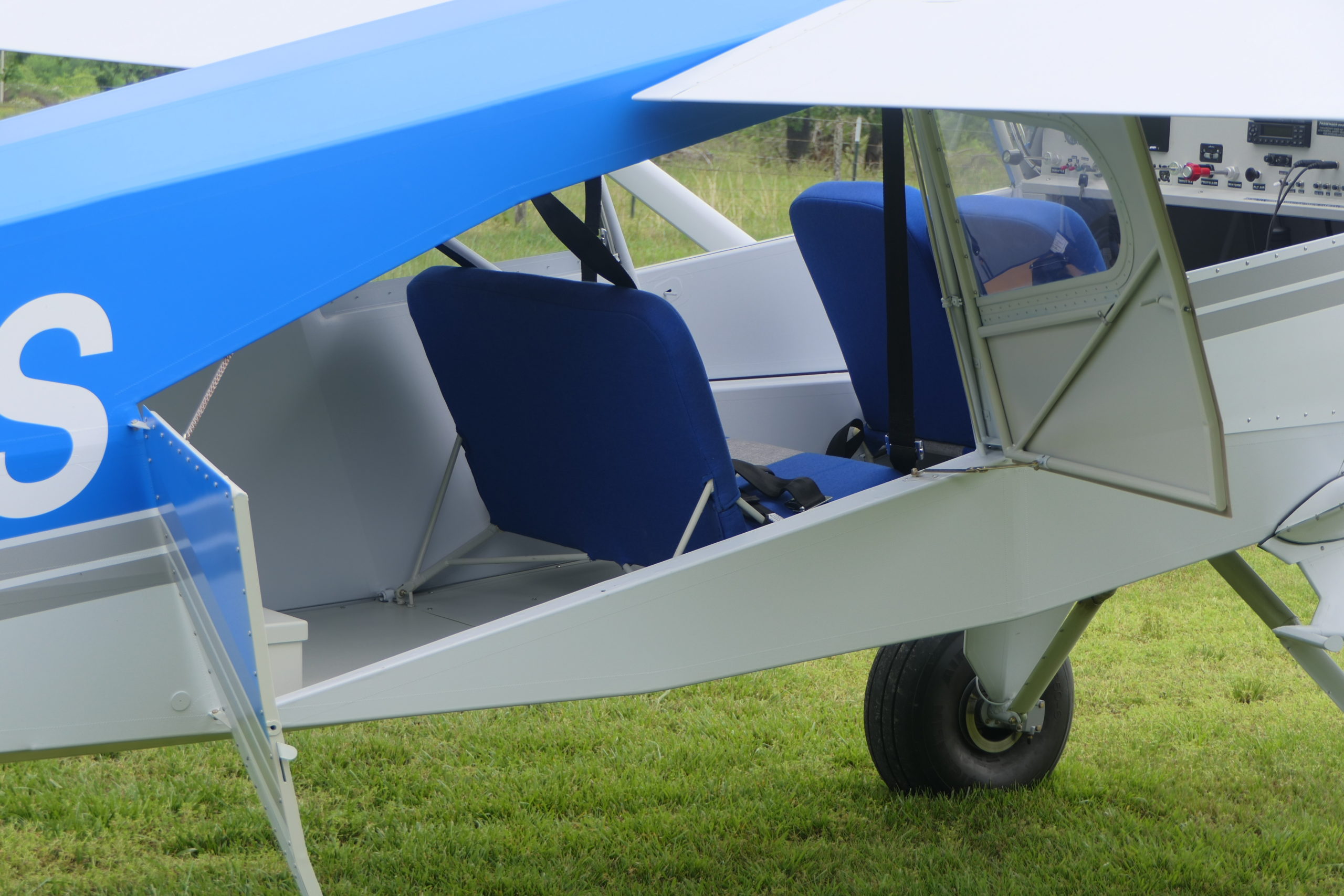
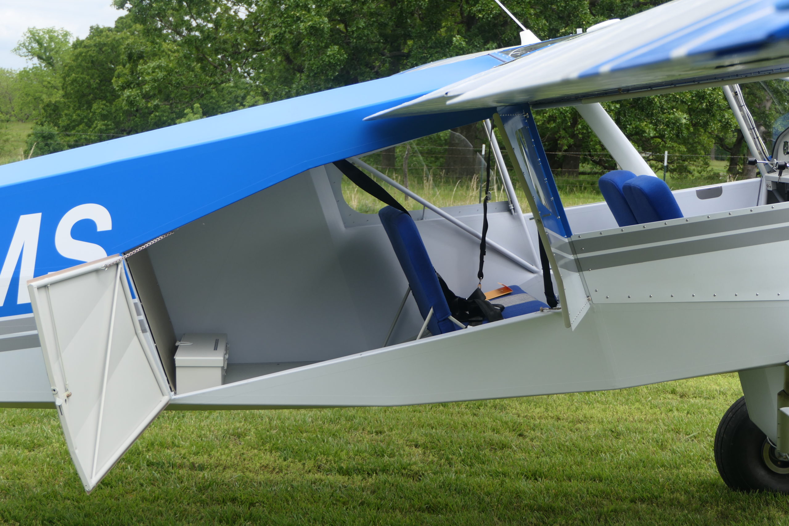
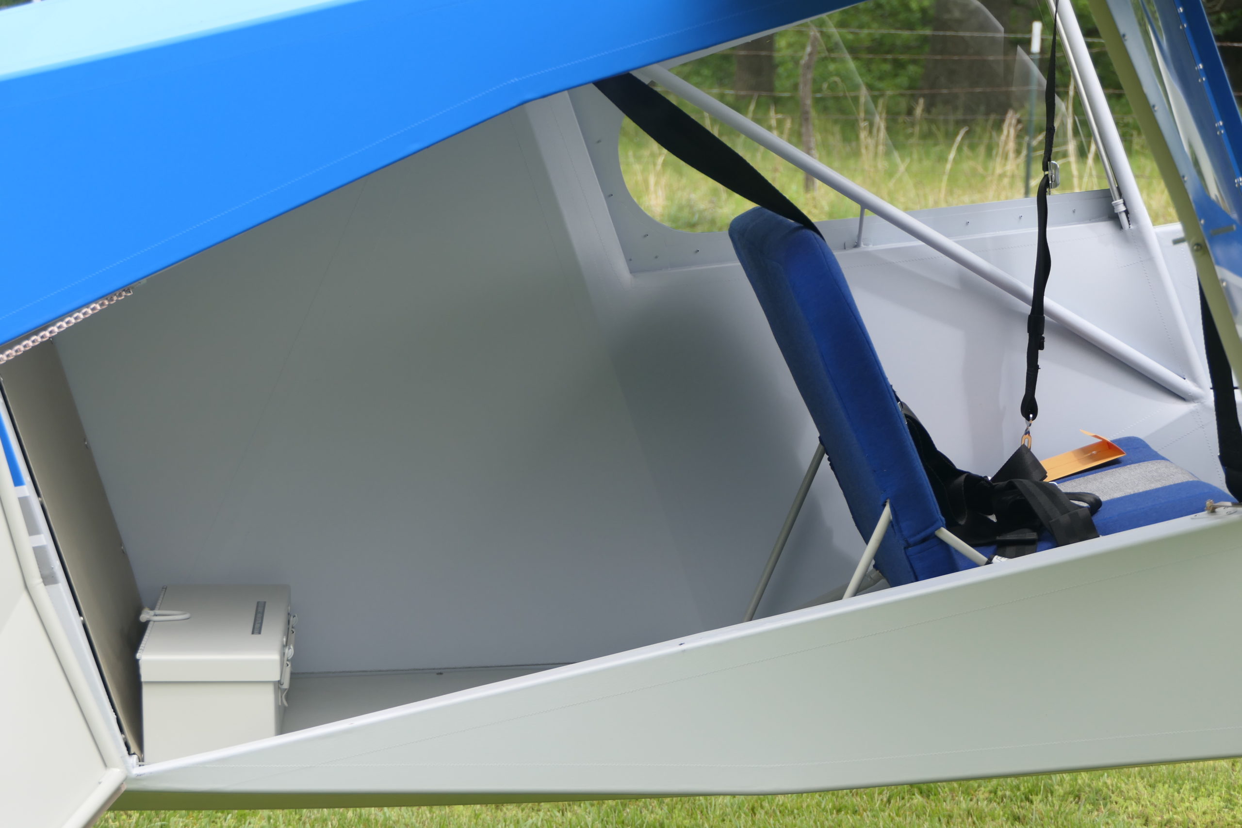
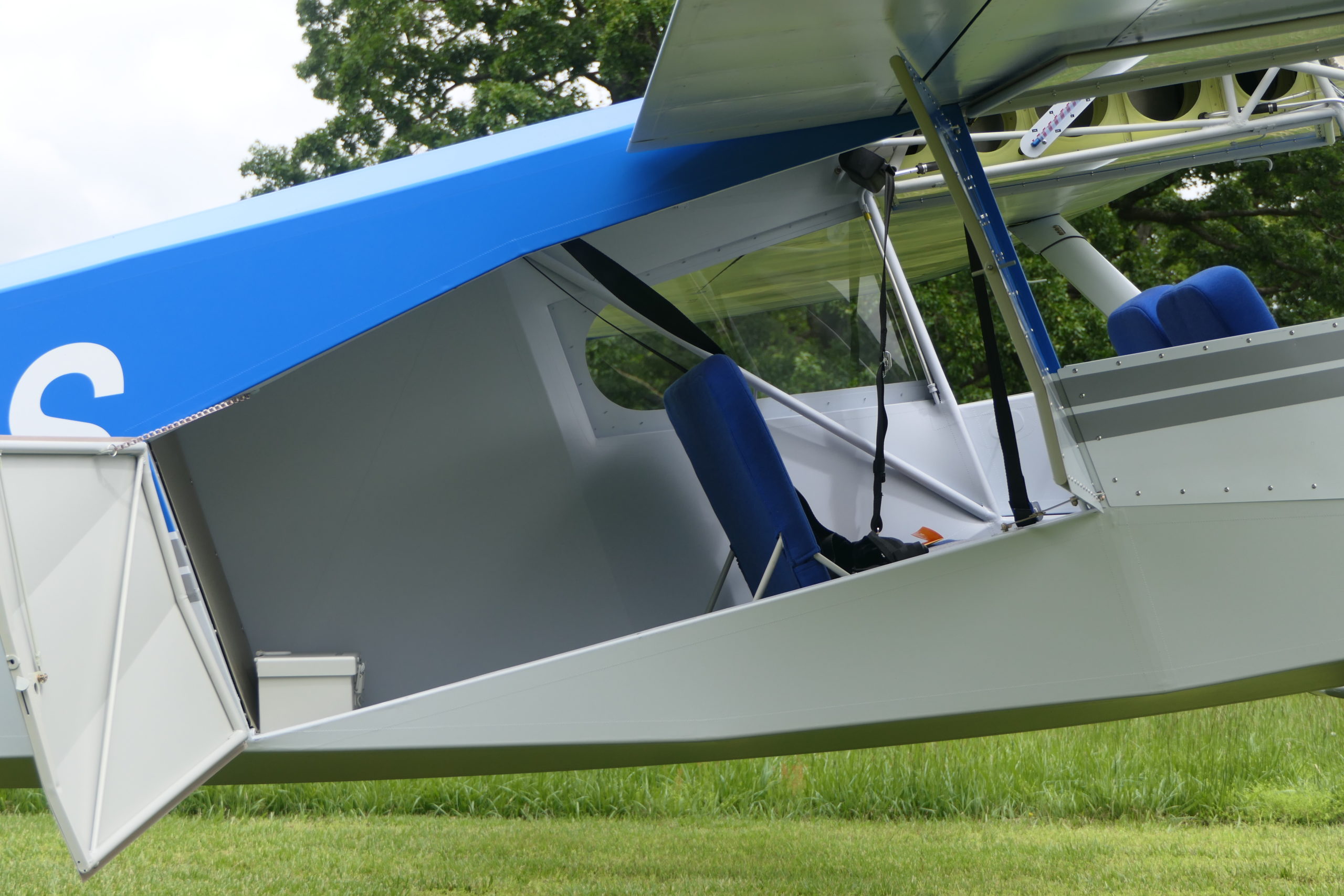
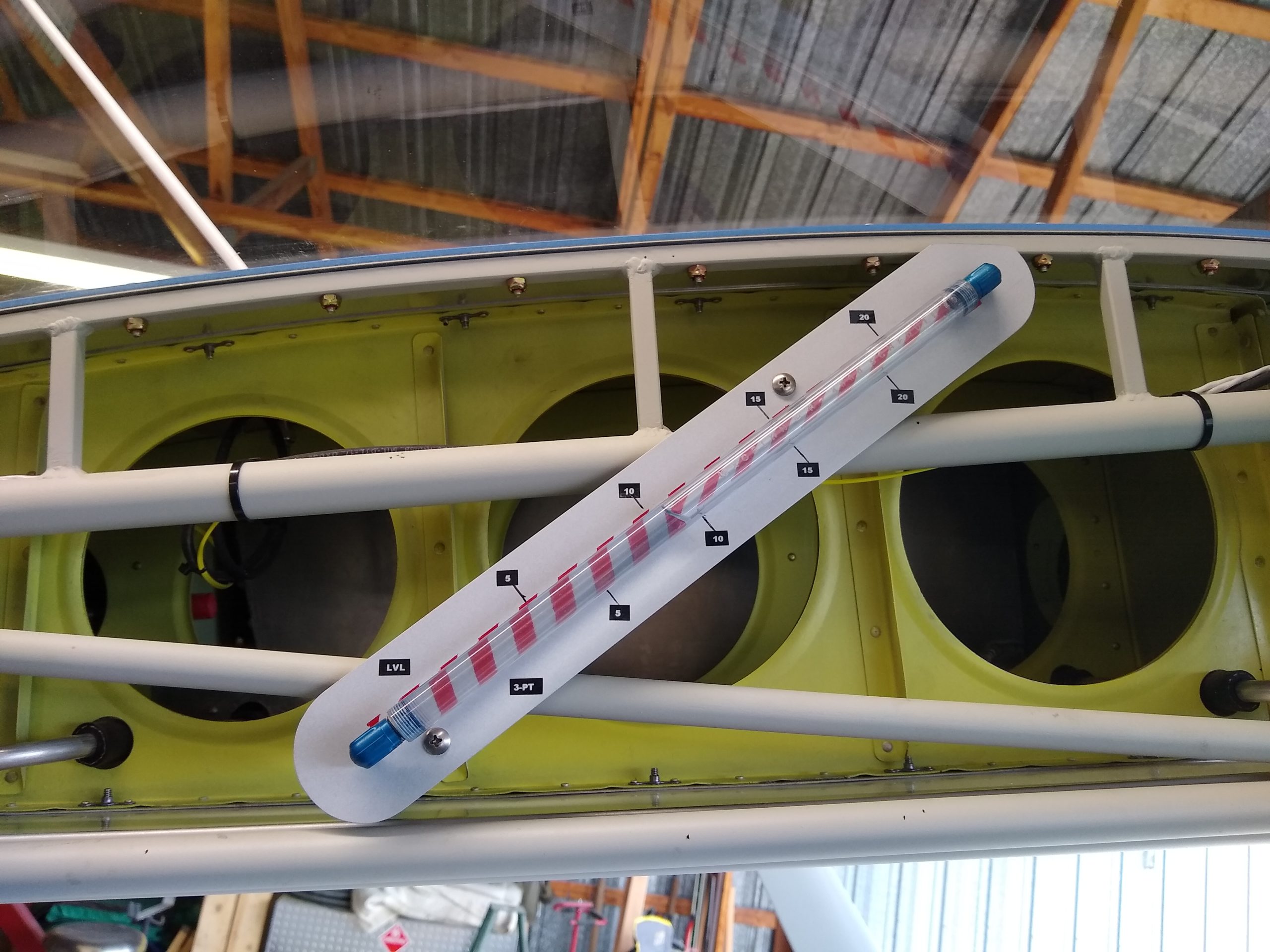
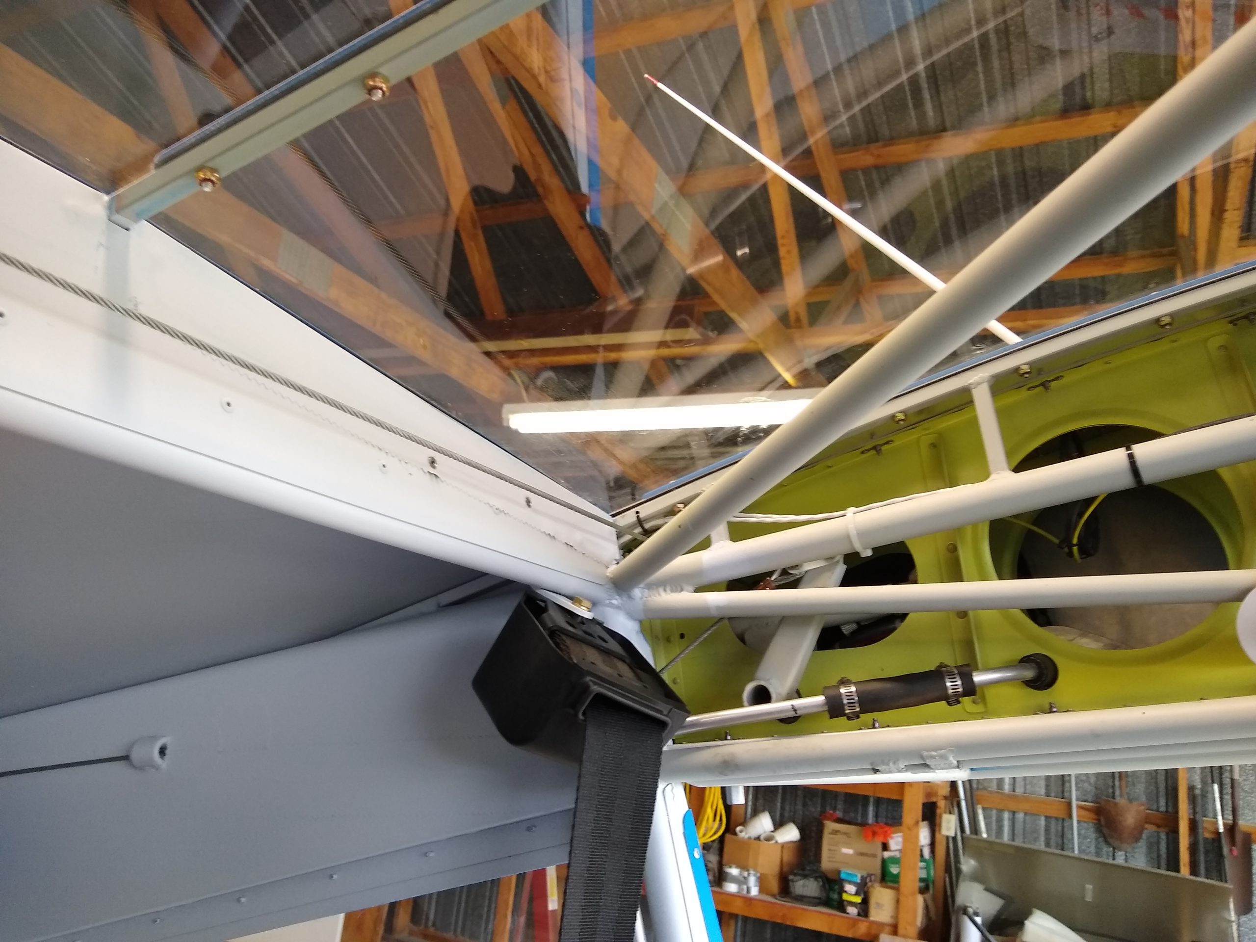
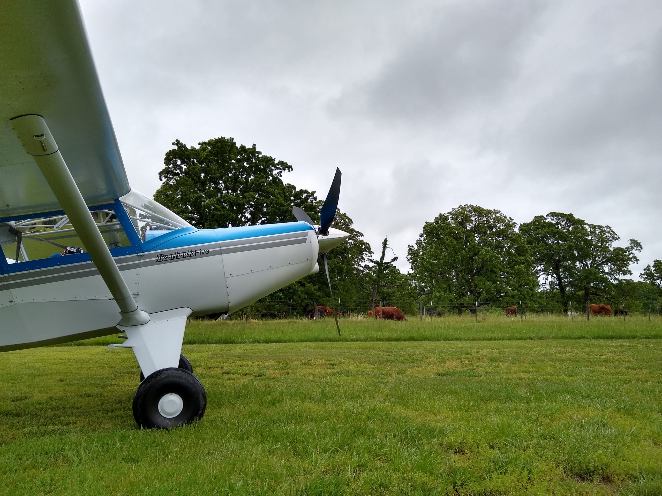
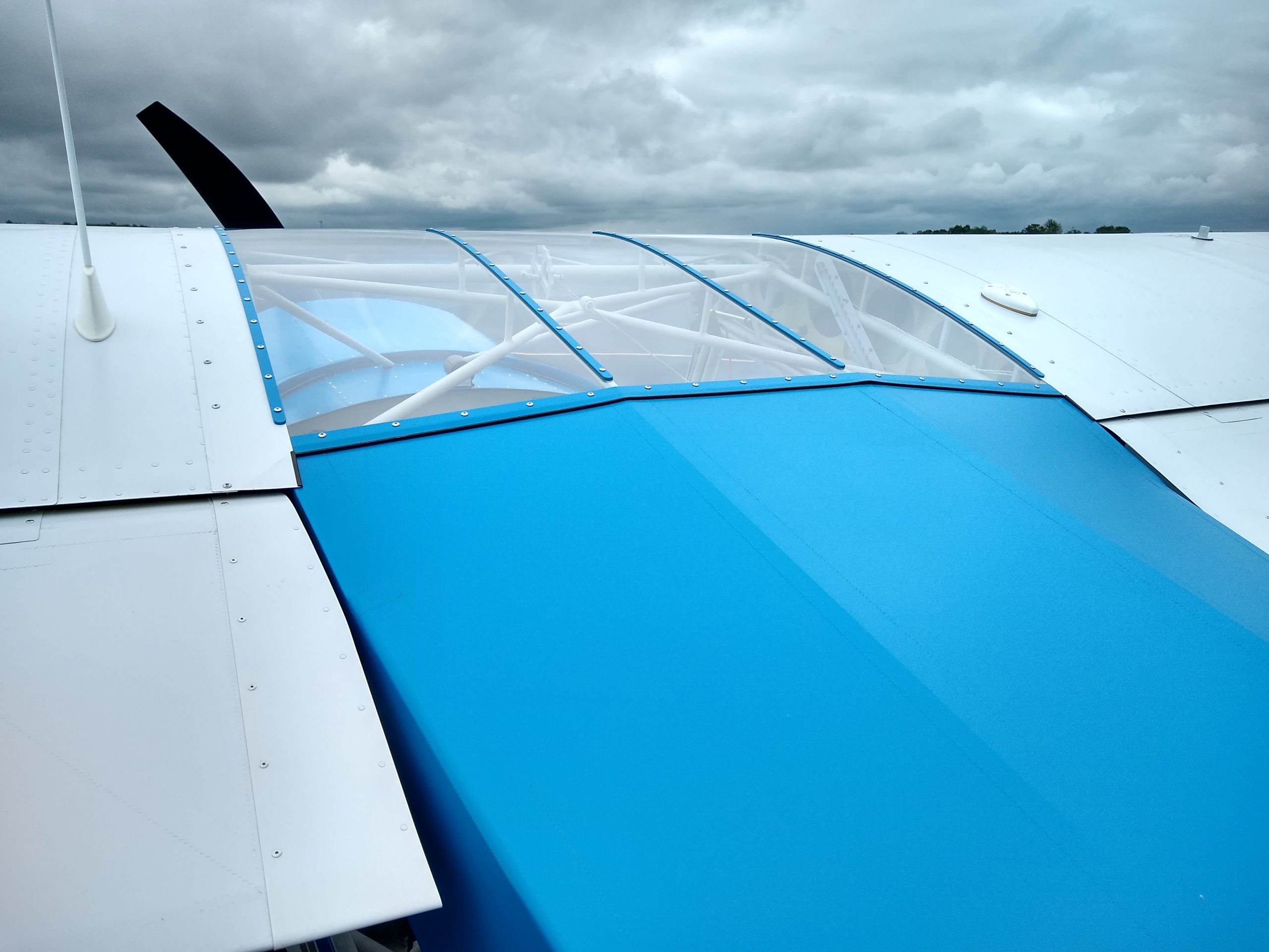
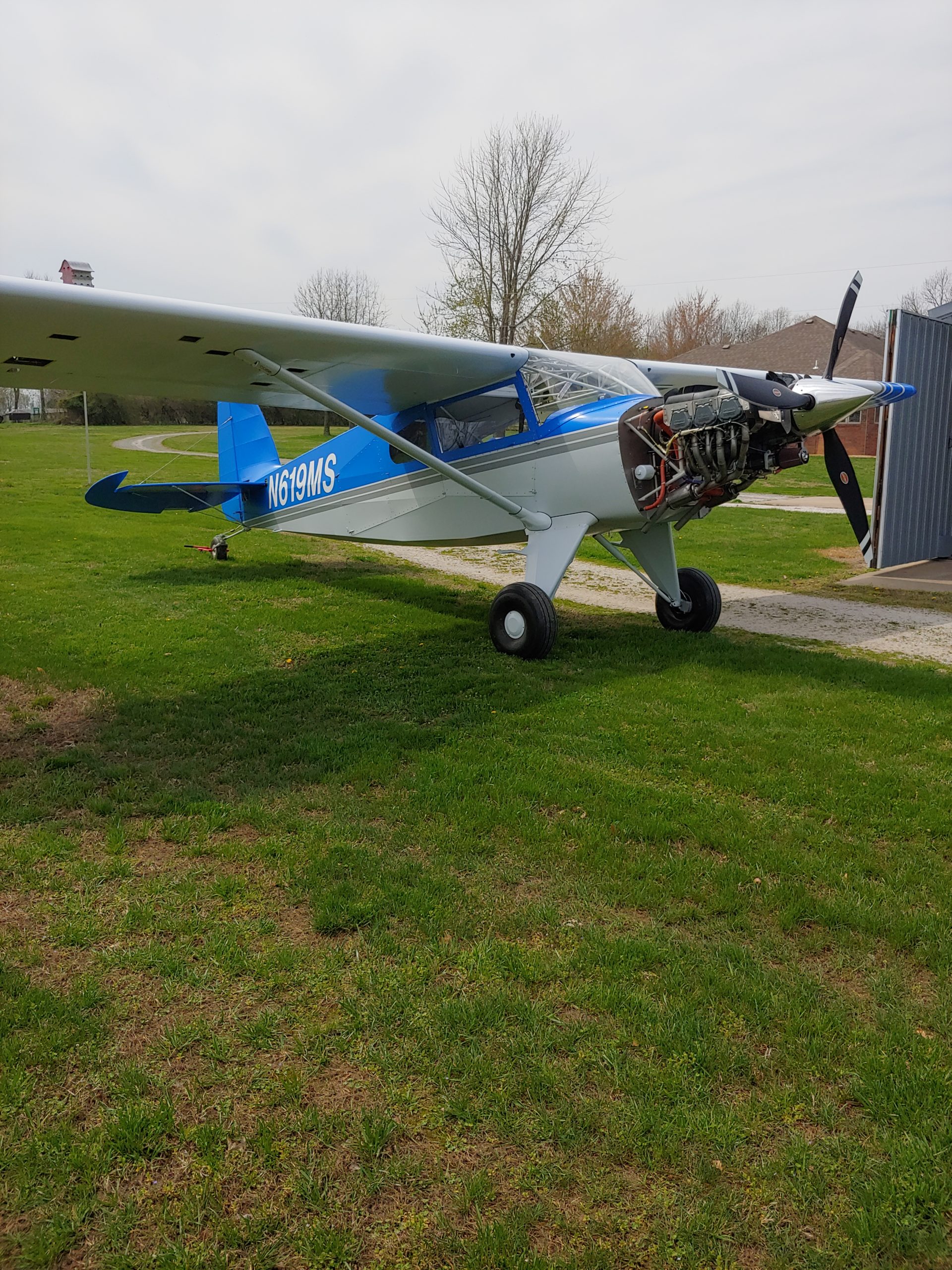
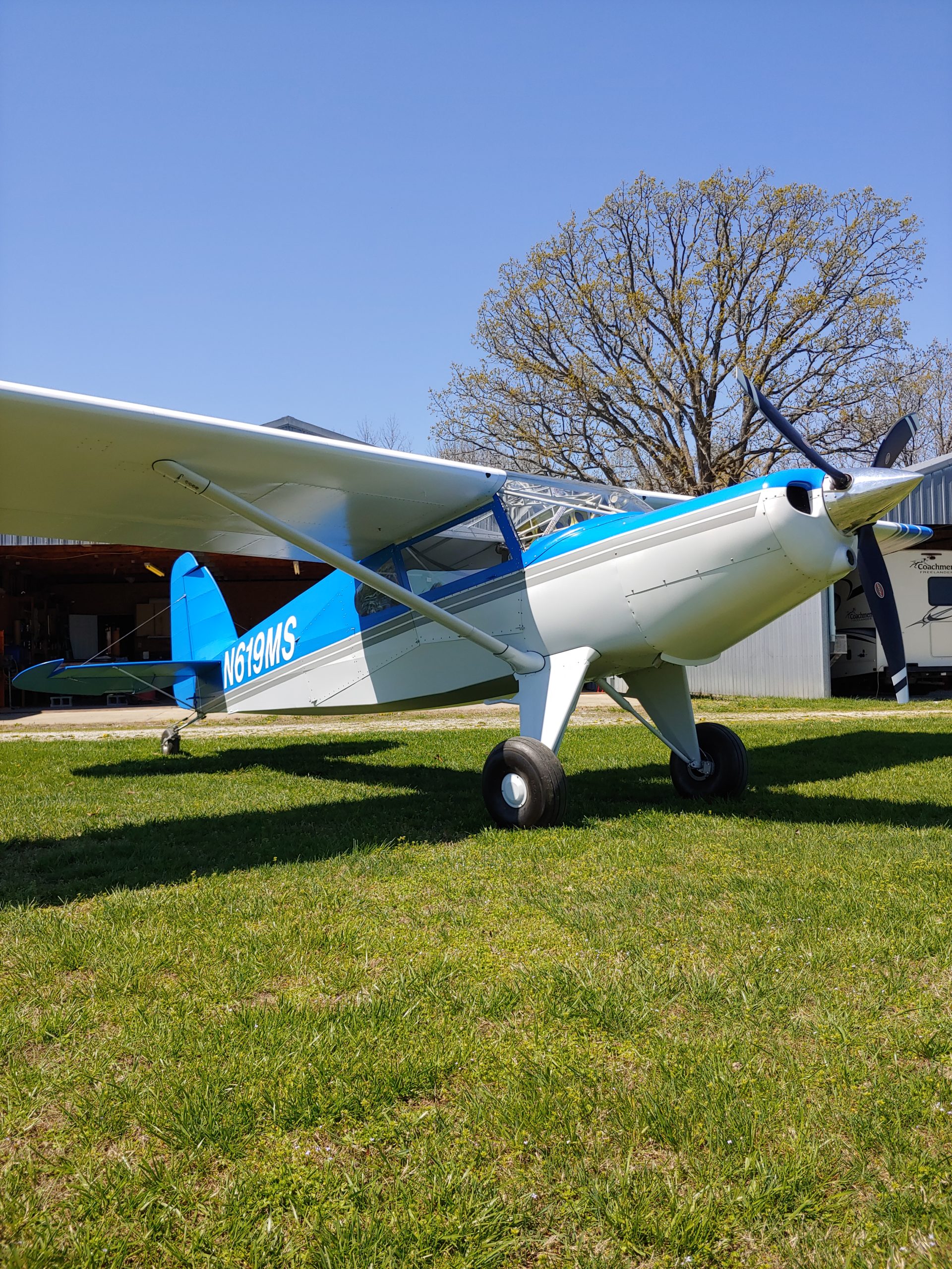
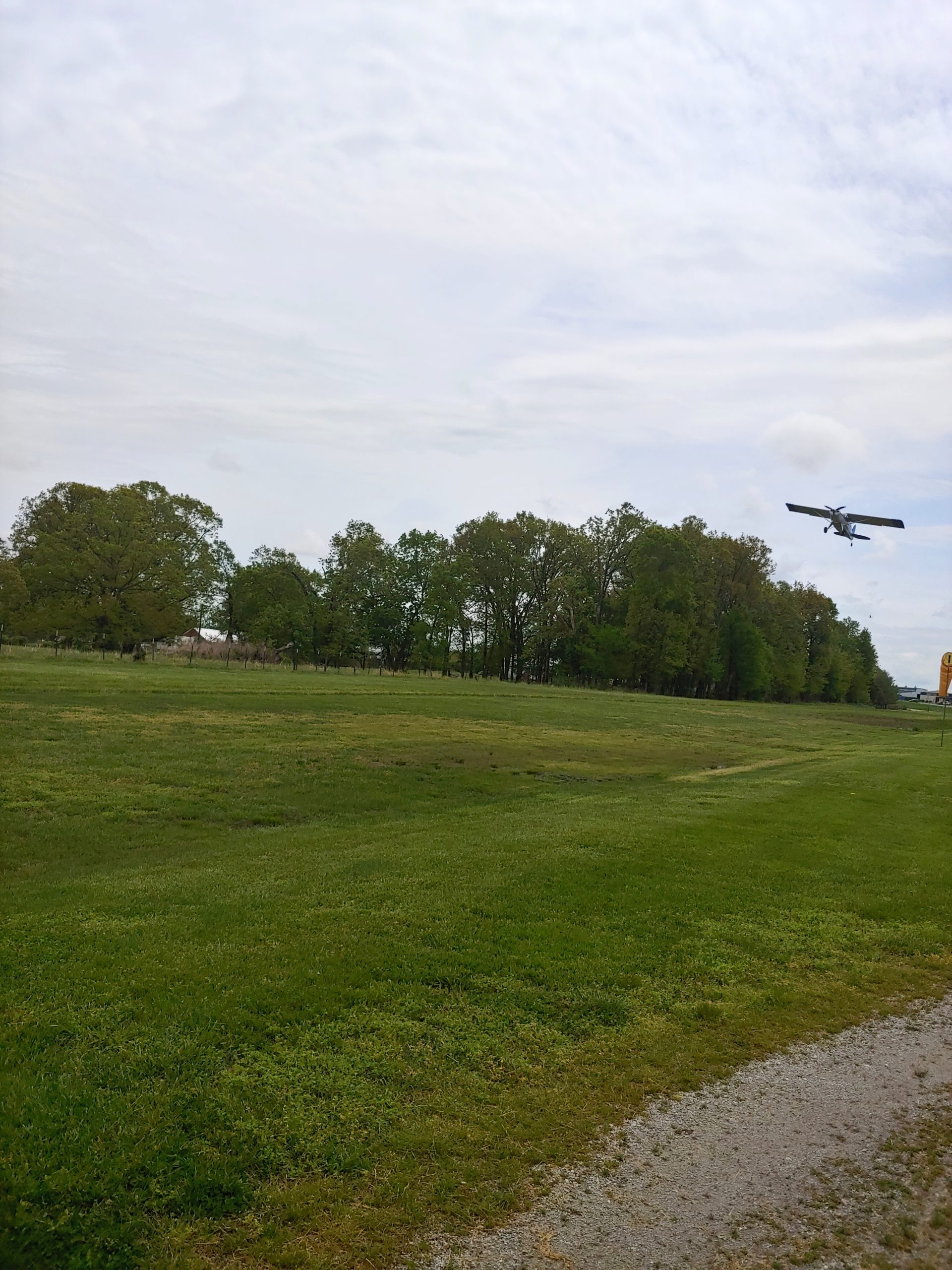
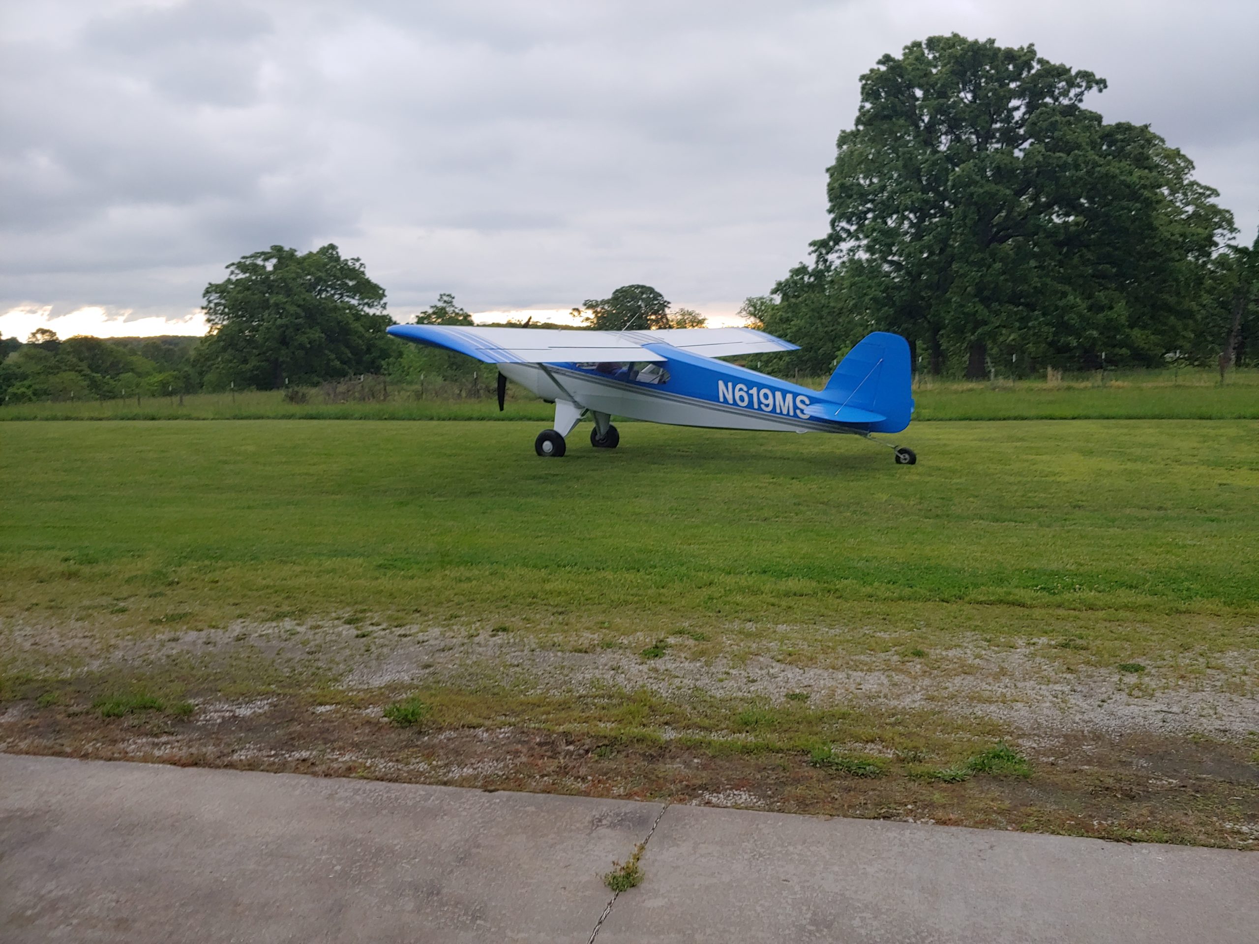
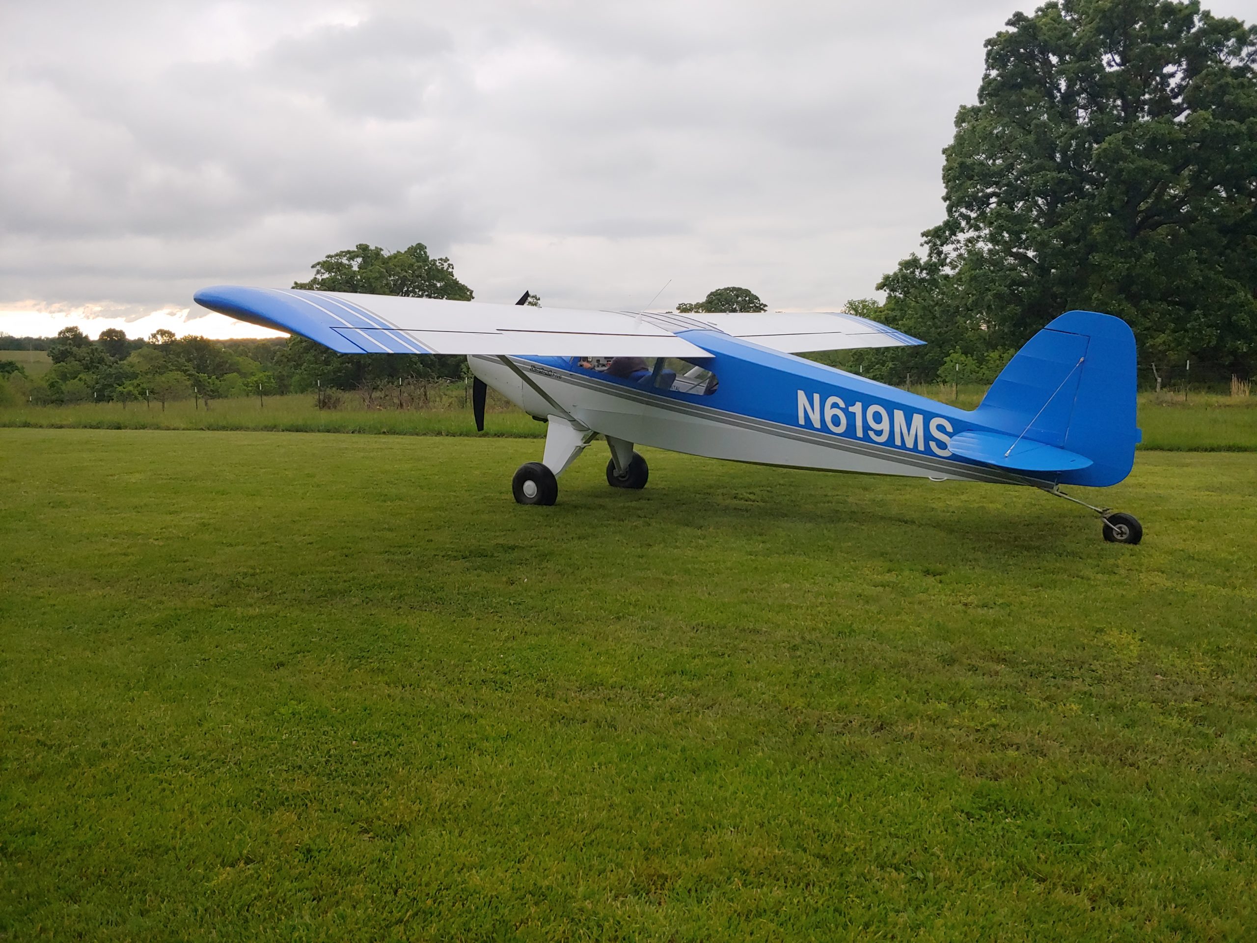
Photos of the flying airplane:











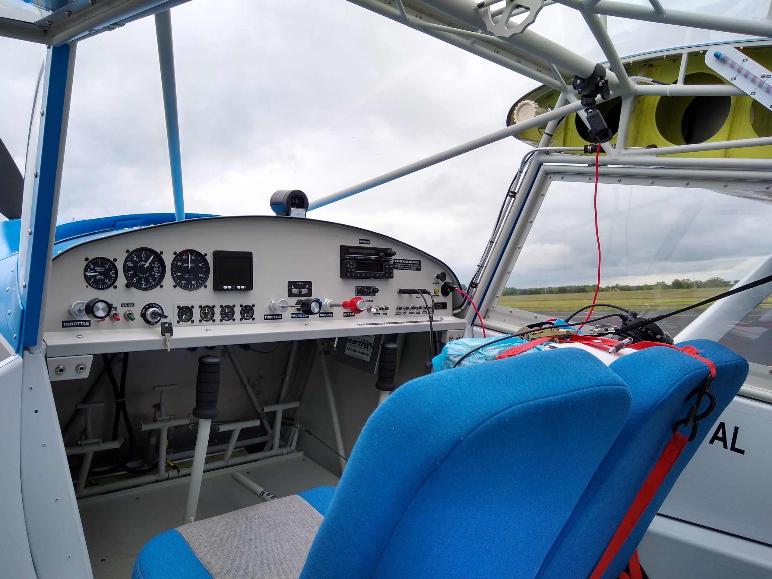
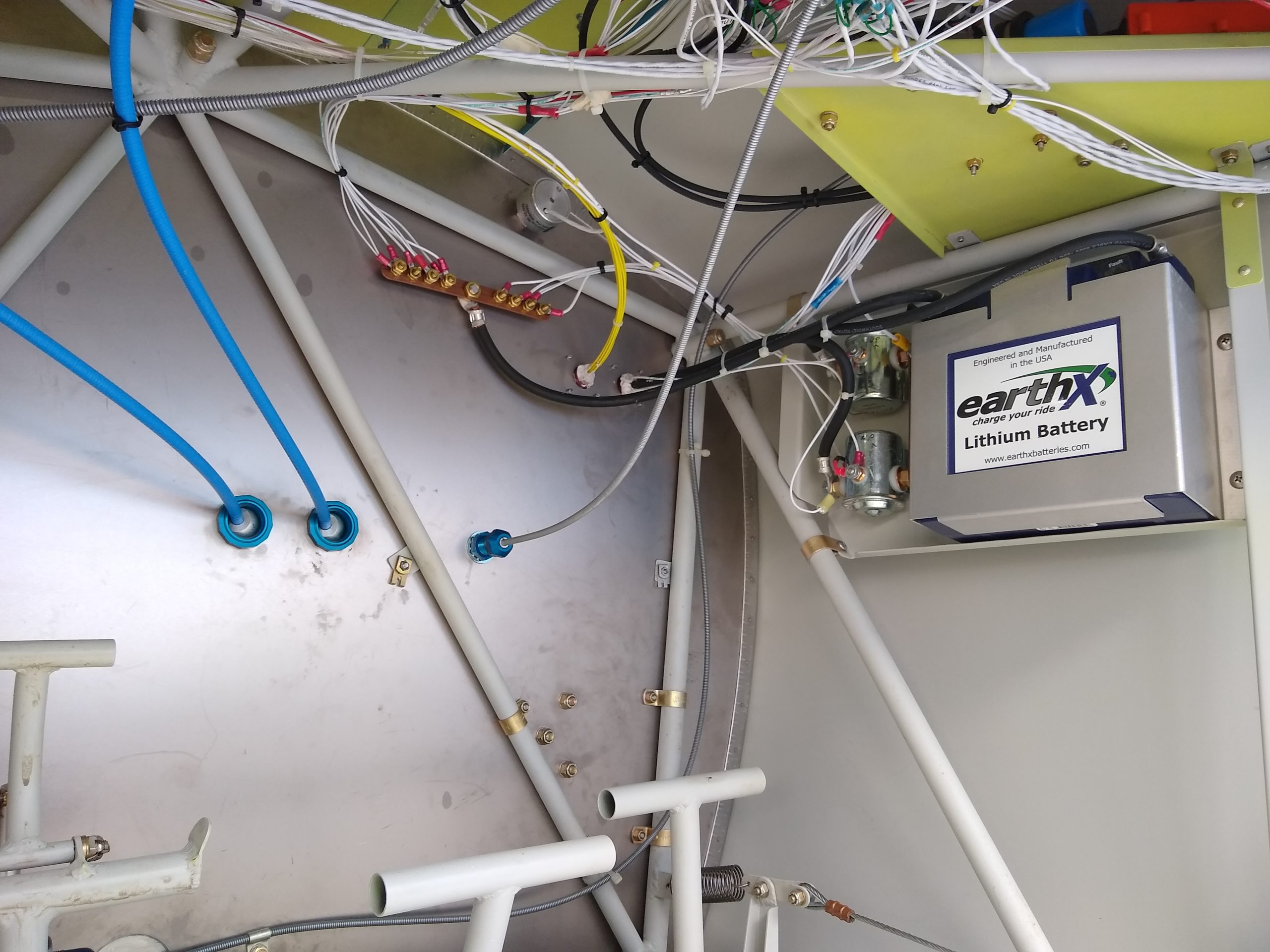
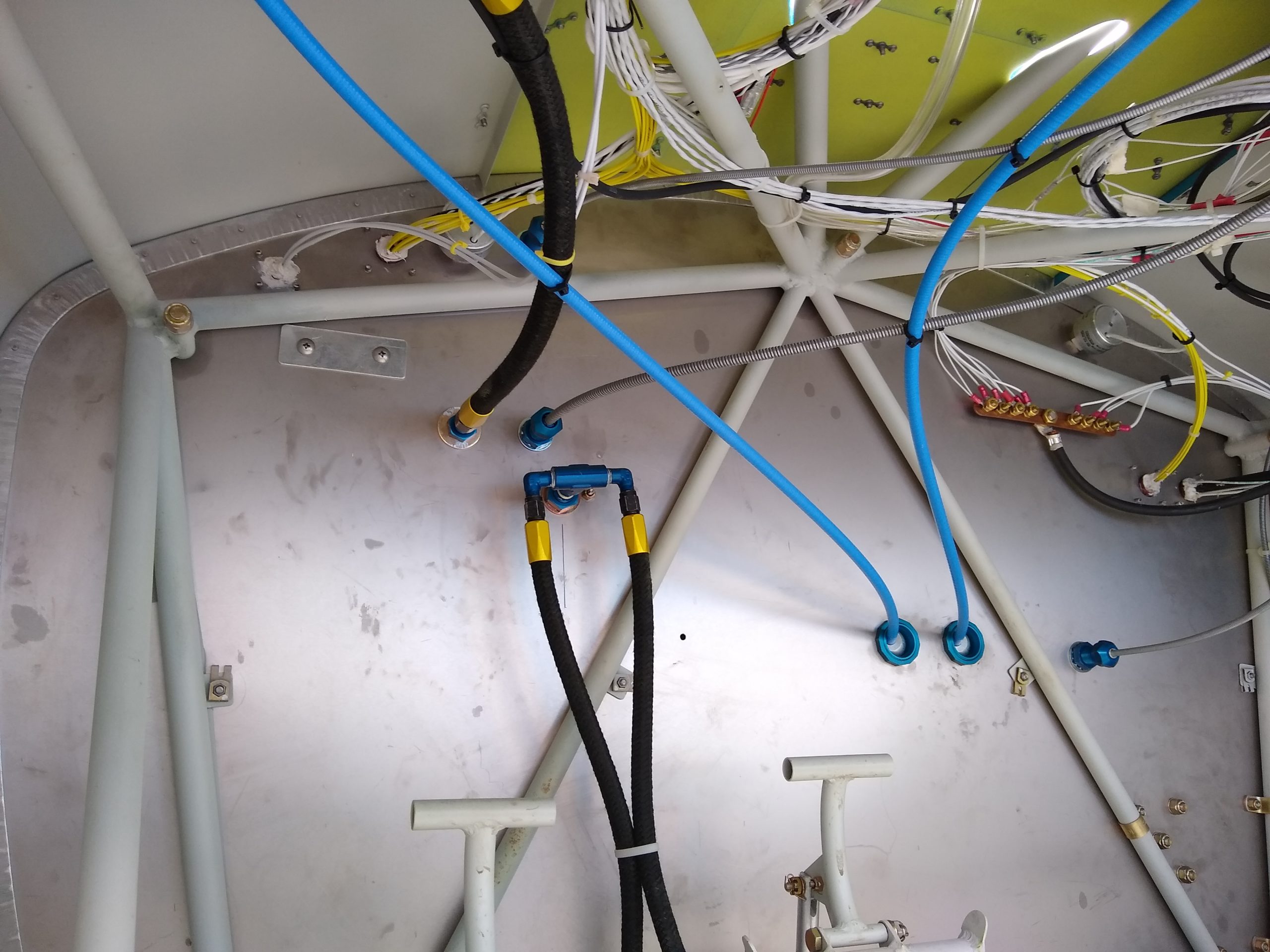
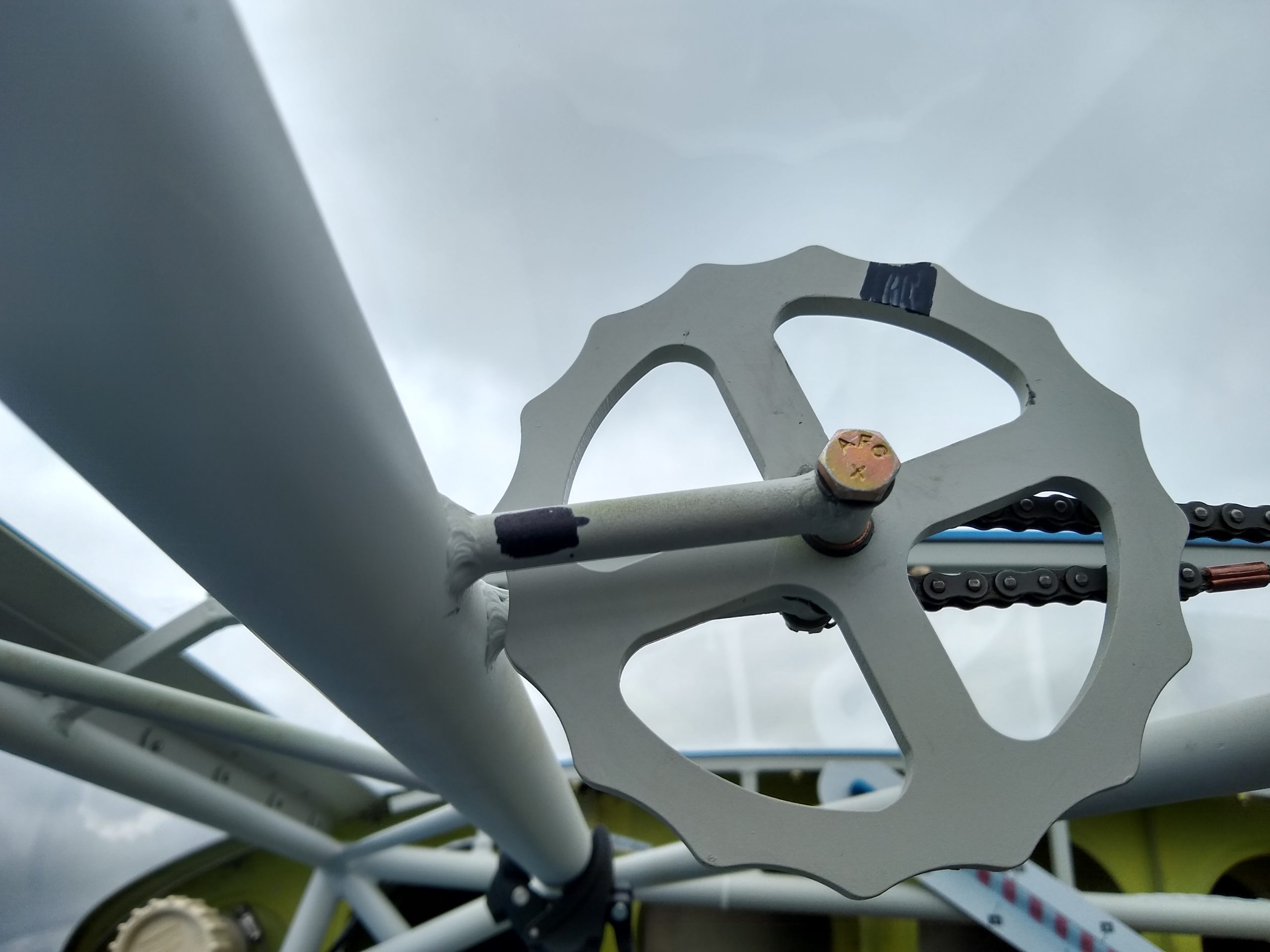



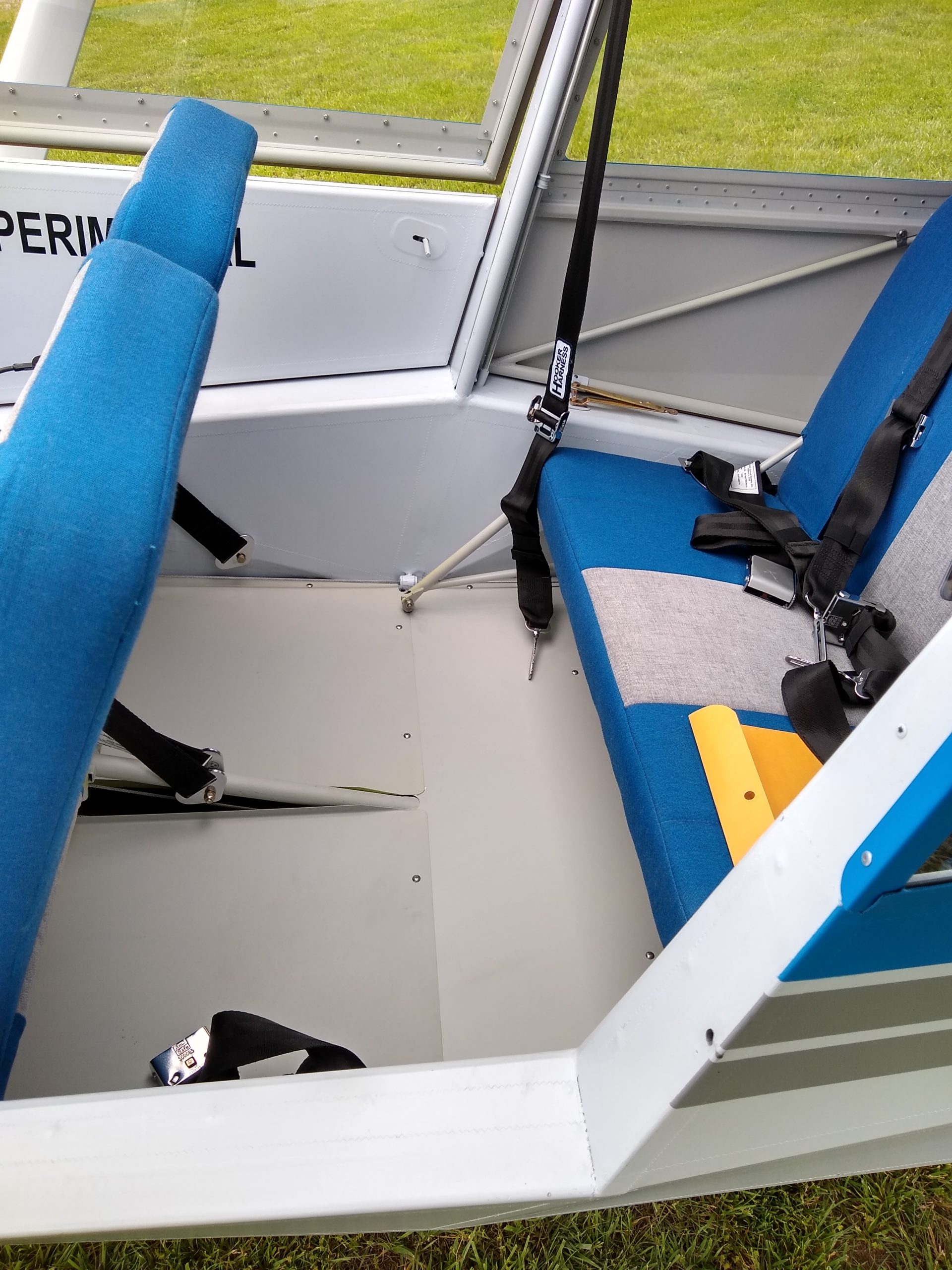


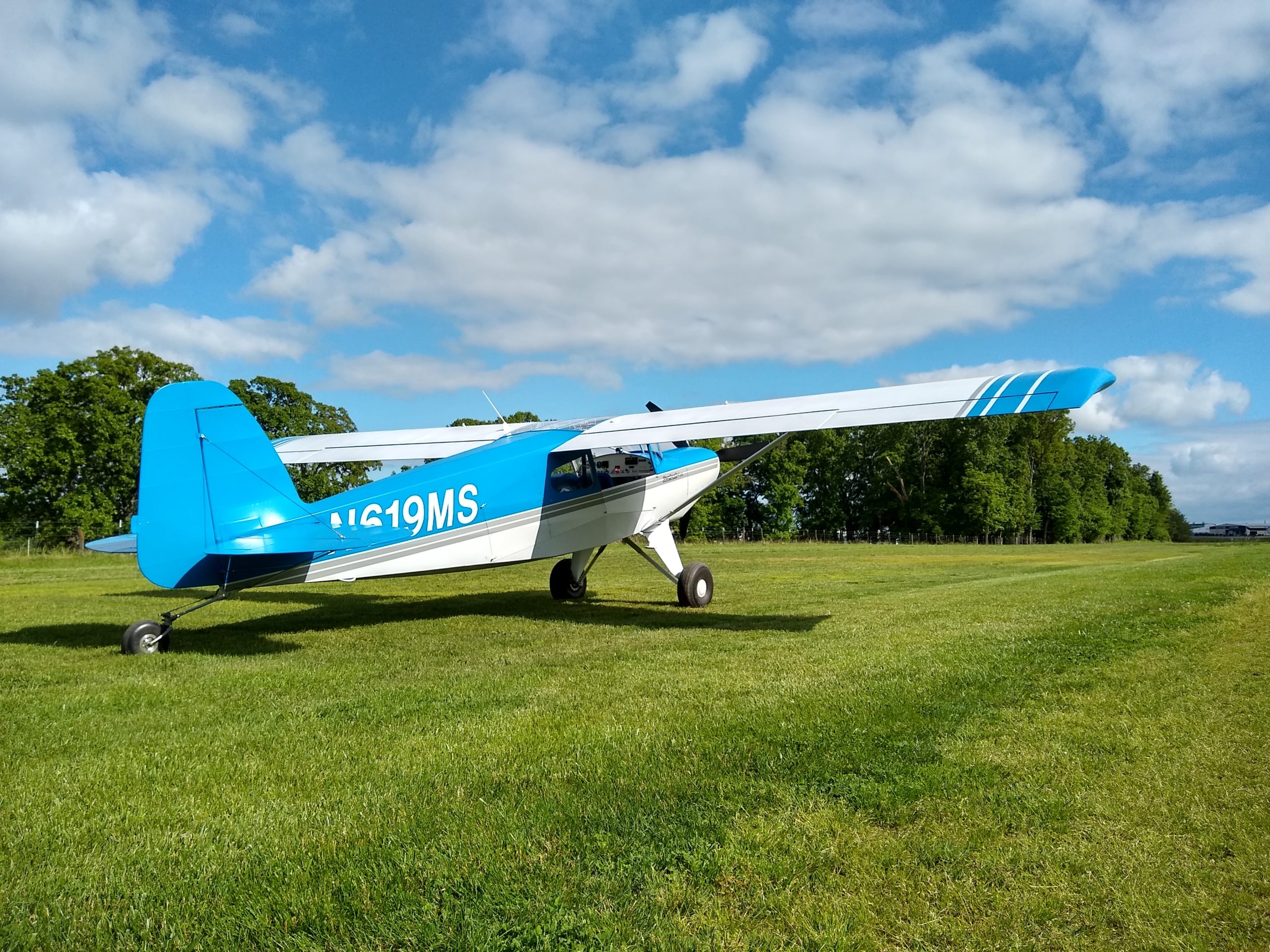

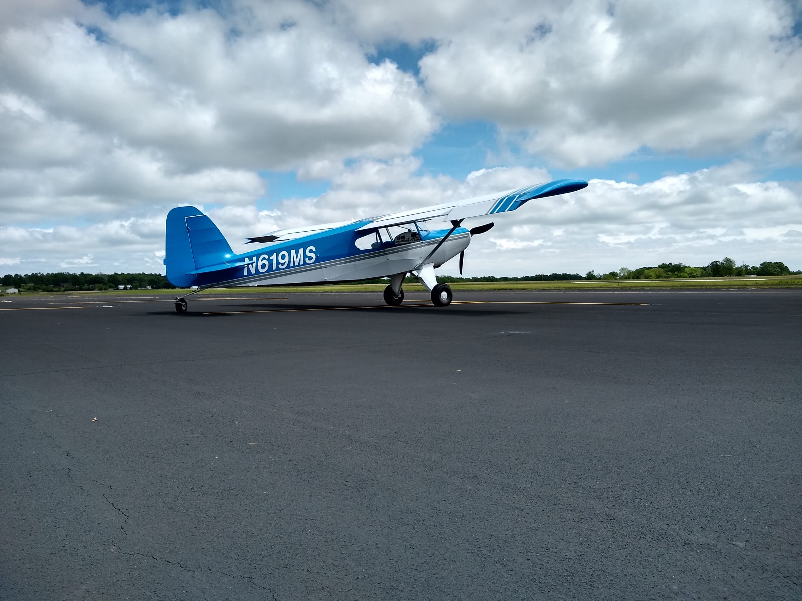
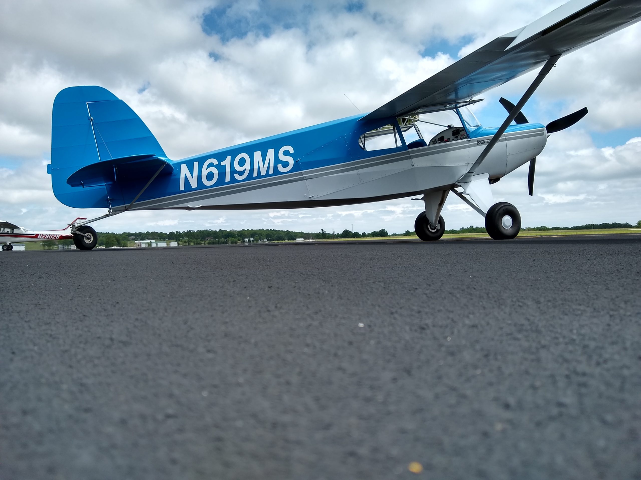
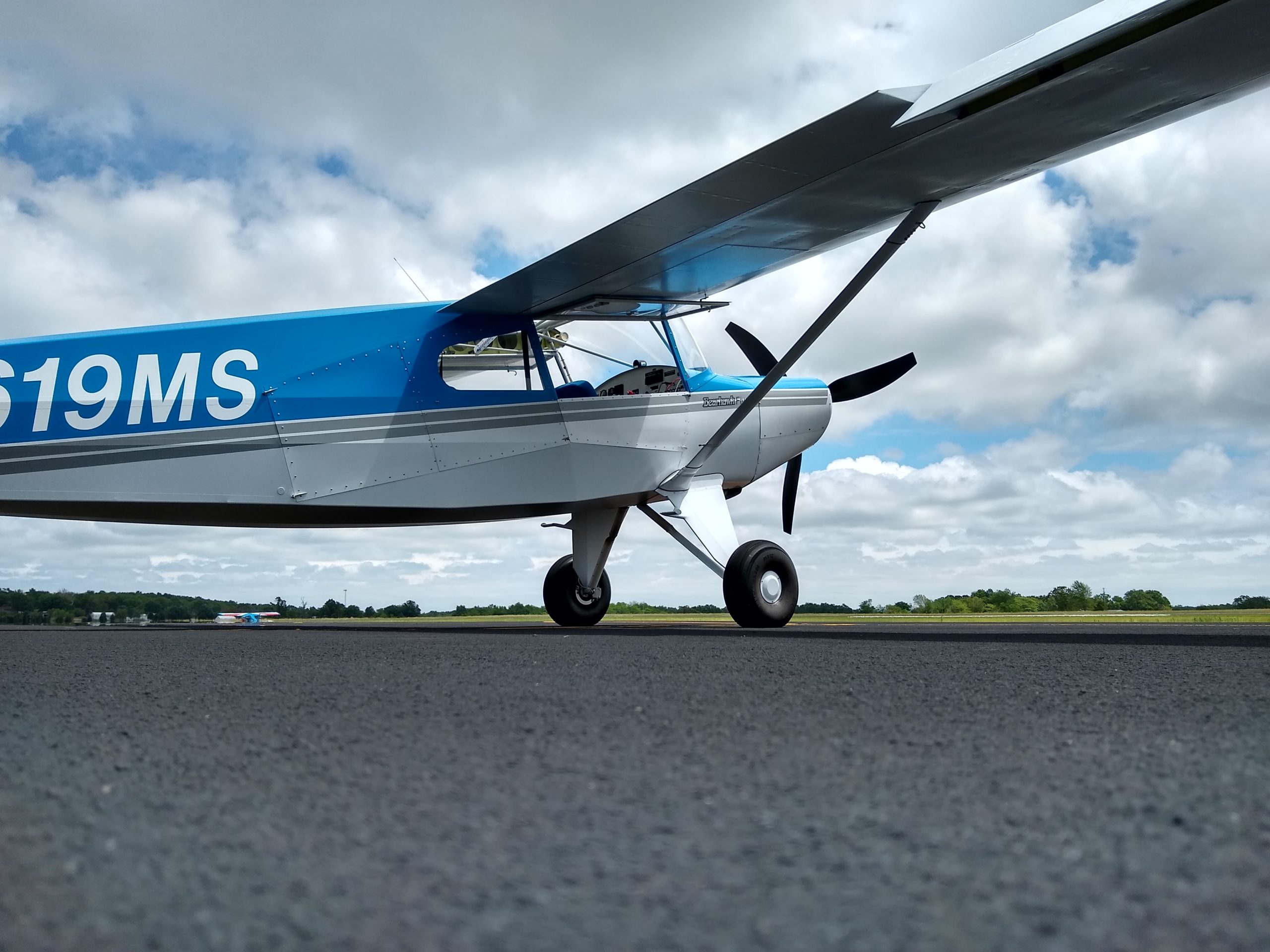
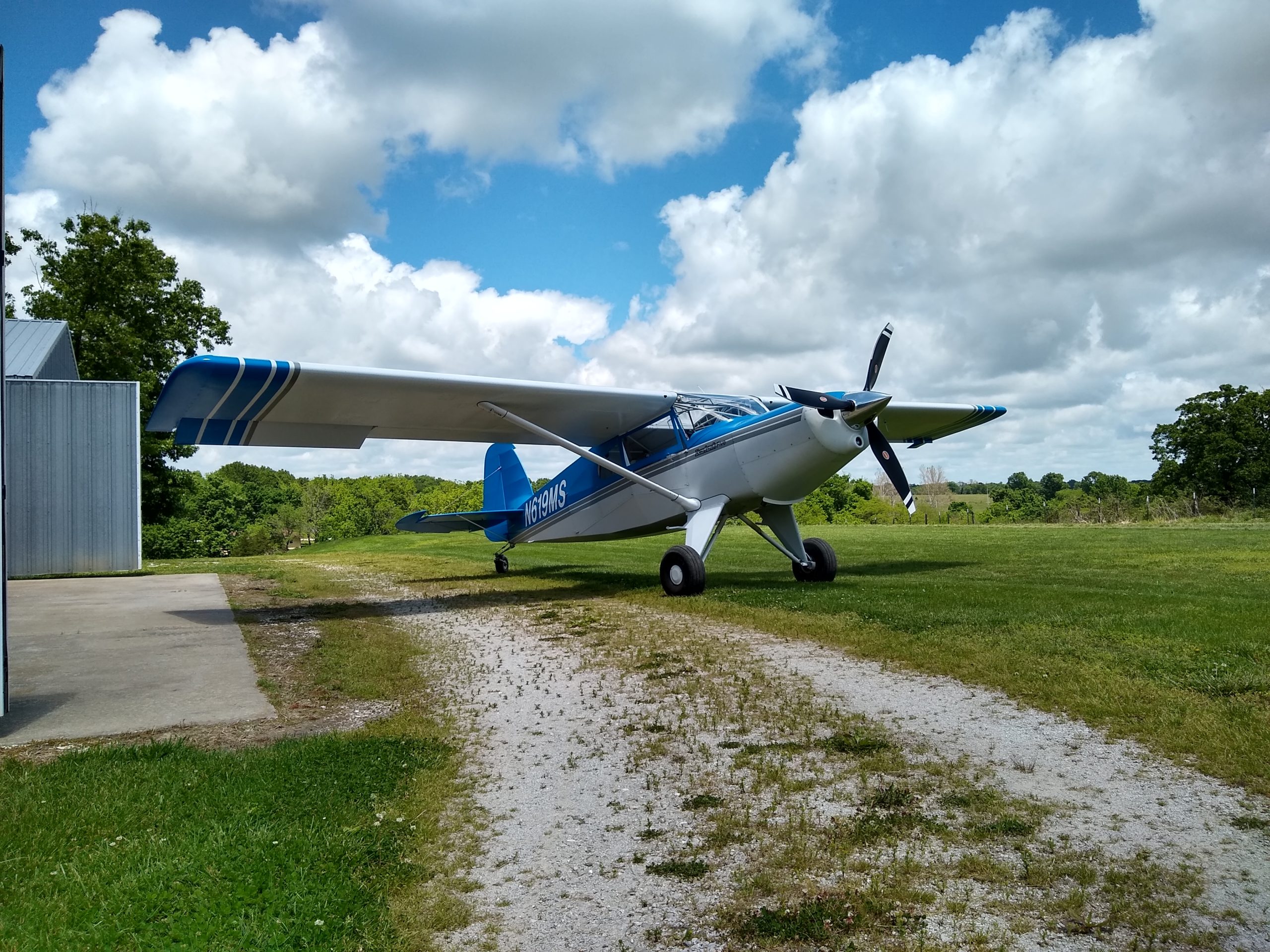


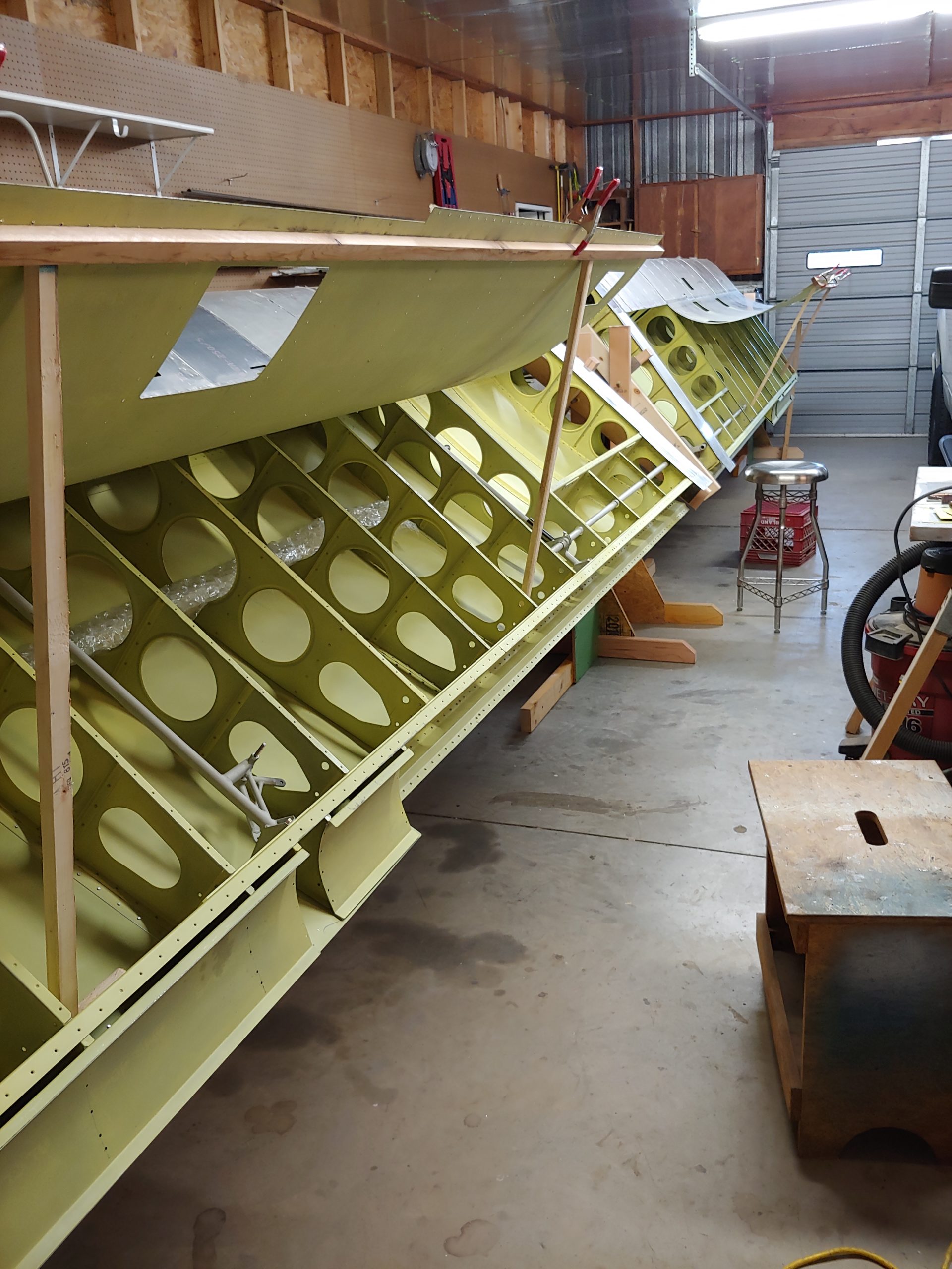
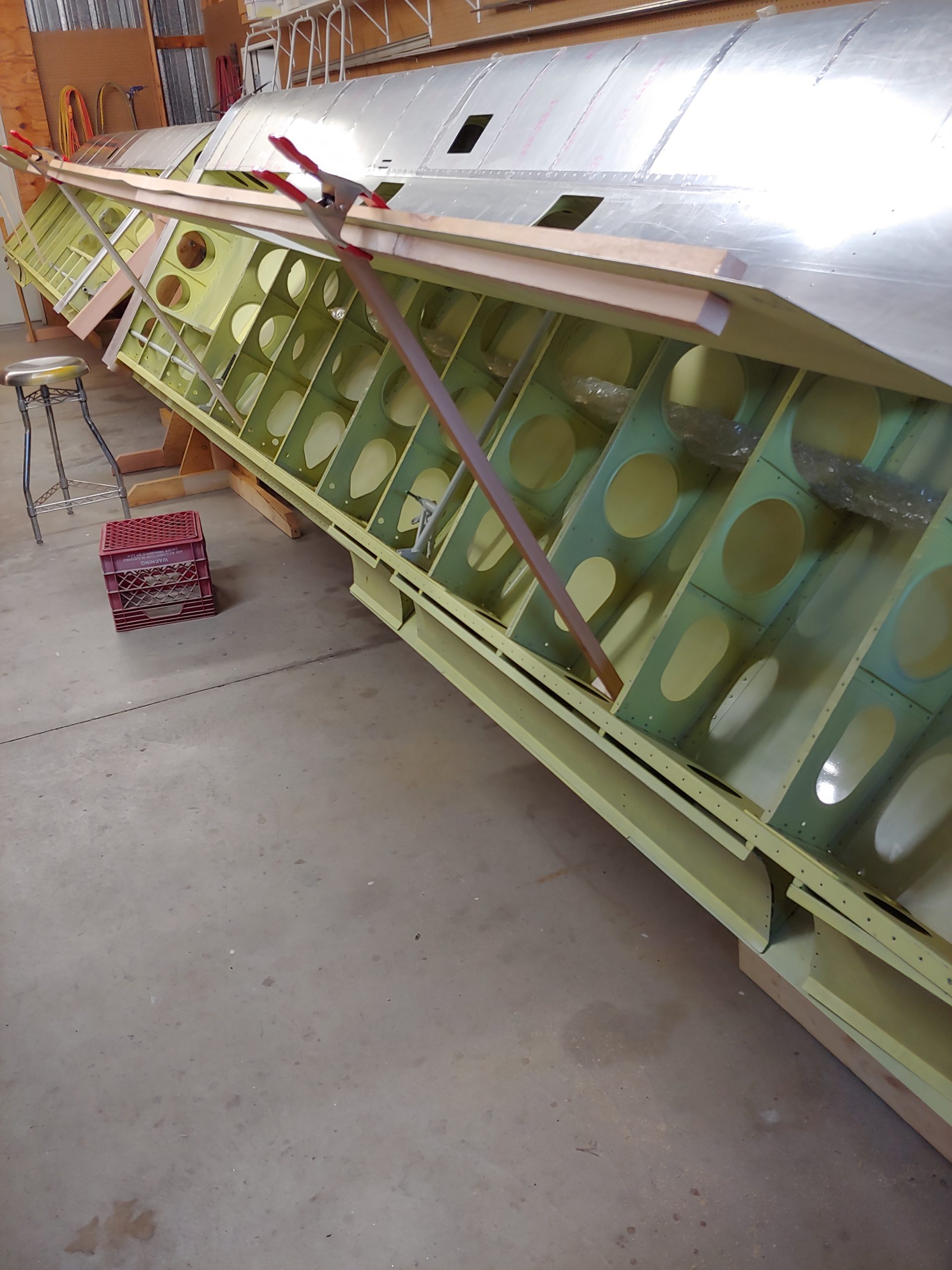
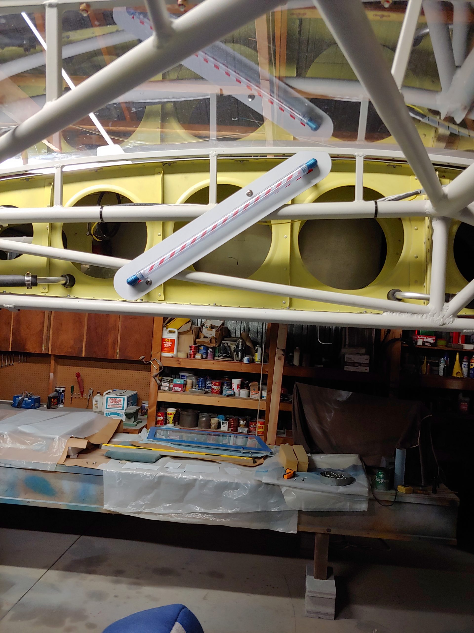
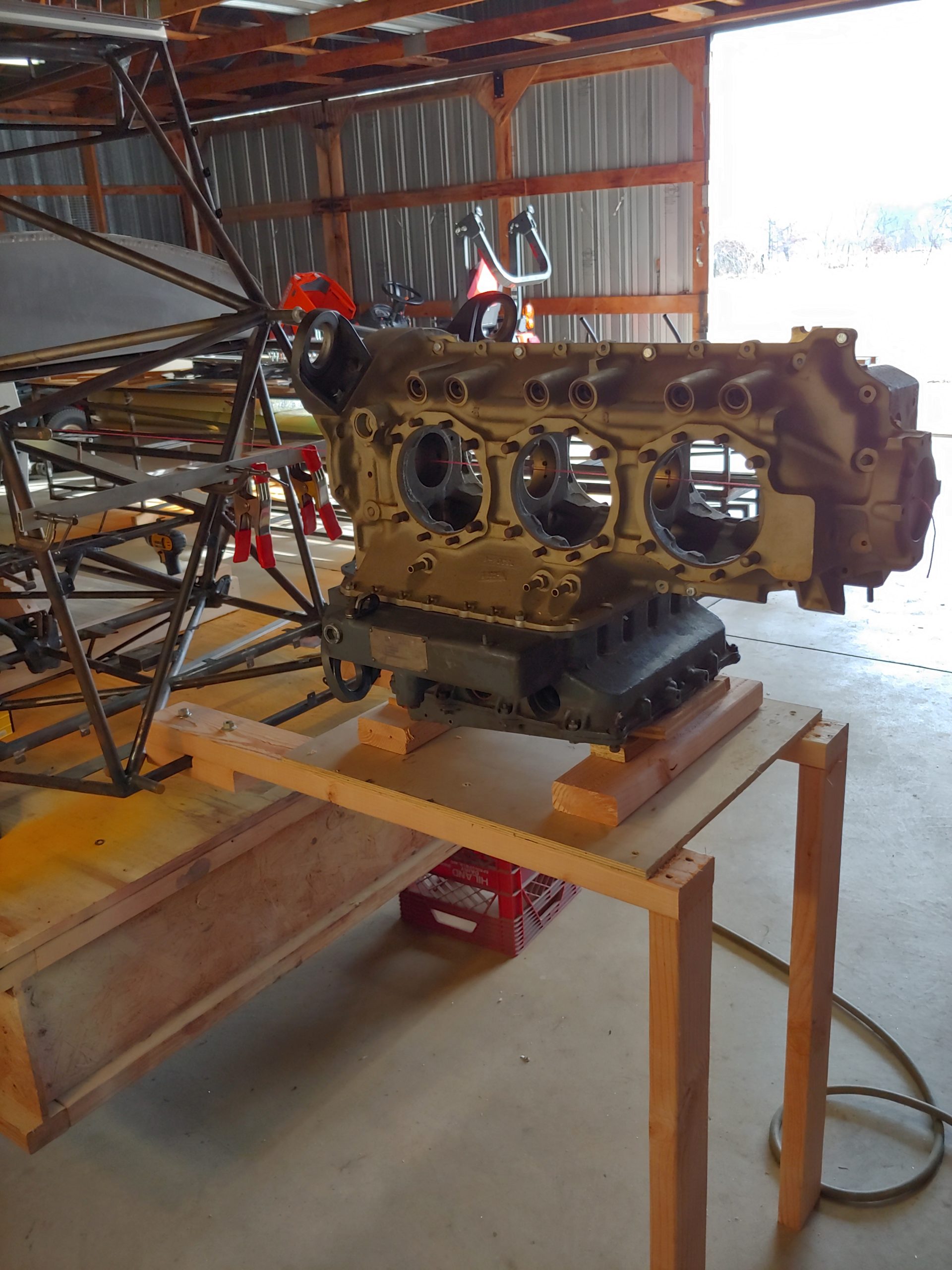
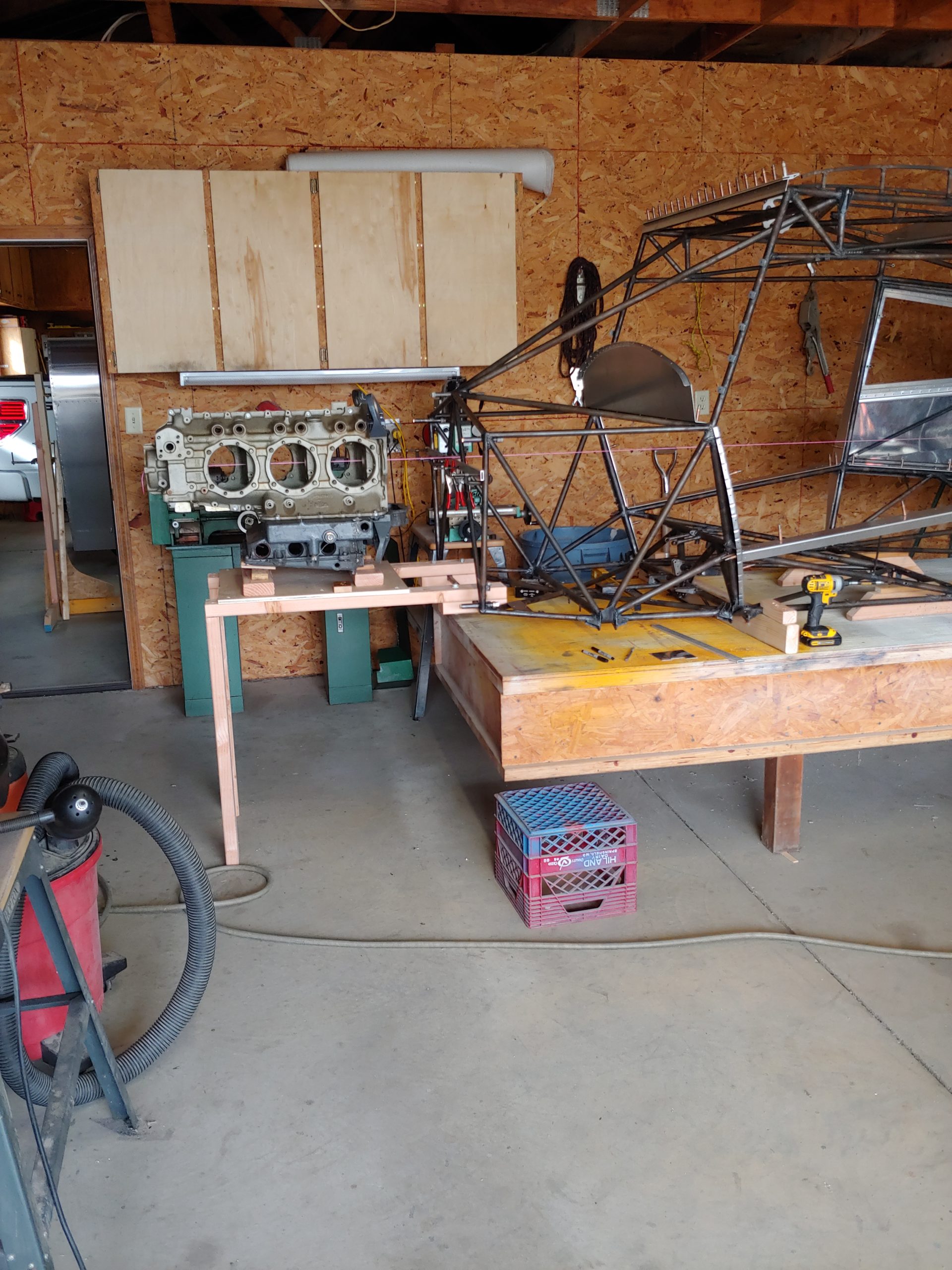
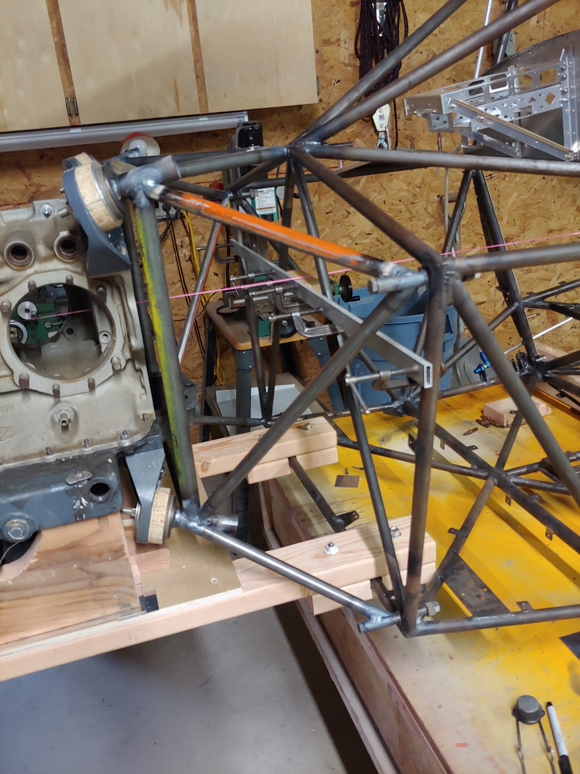
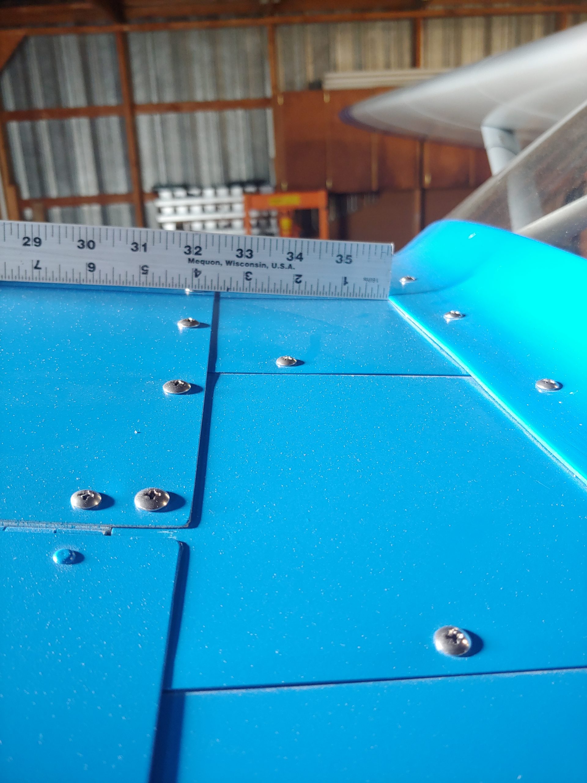
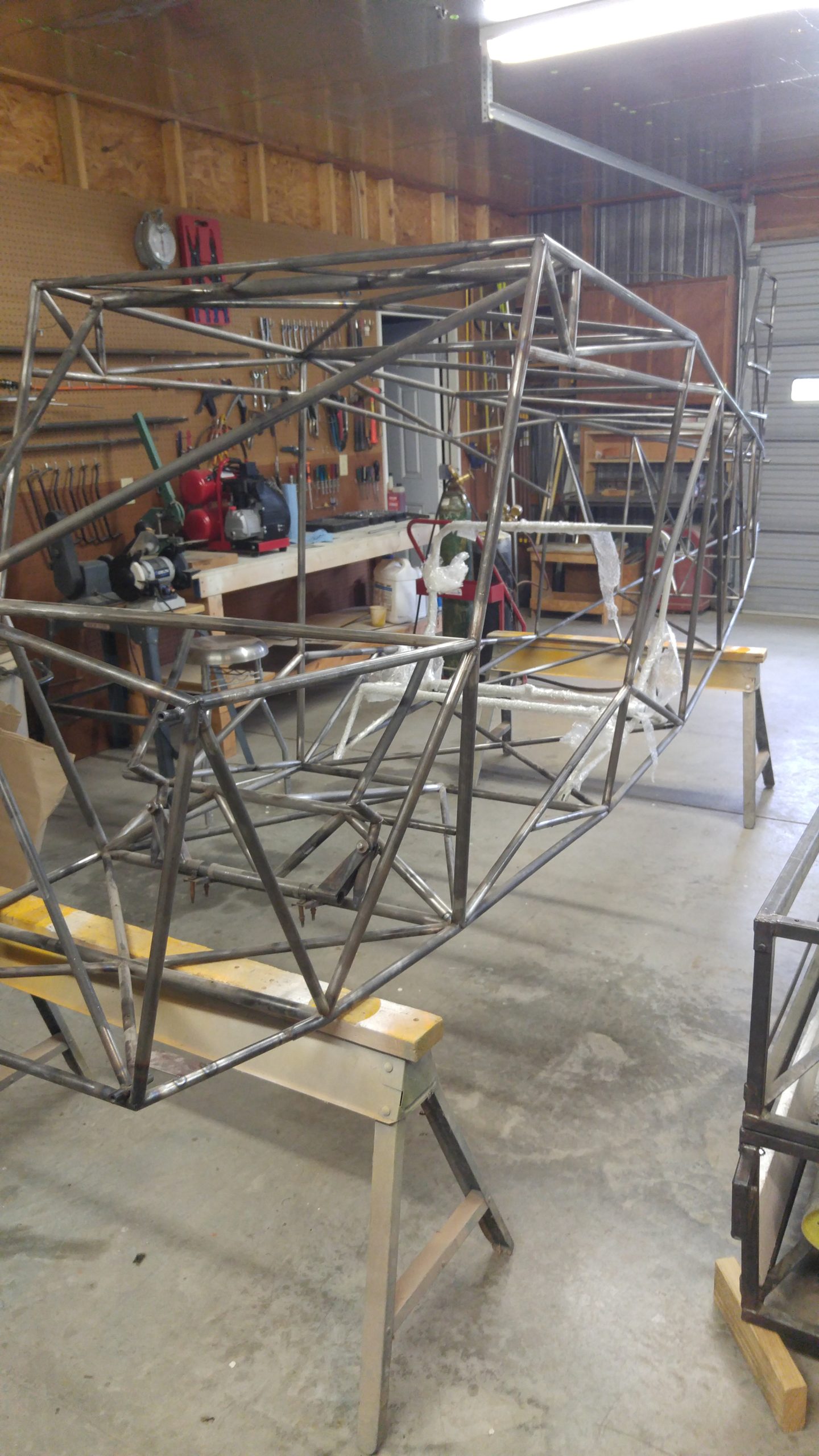
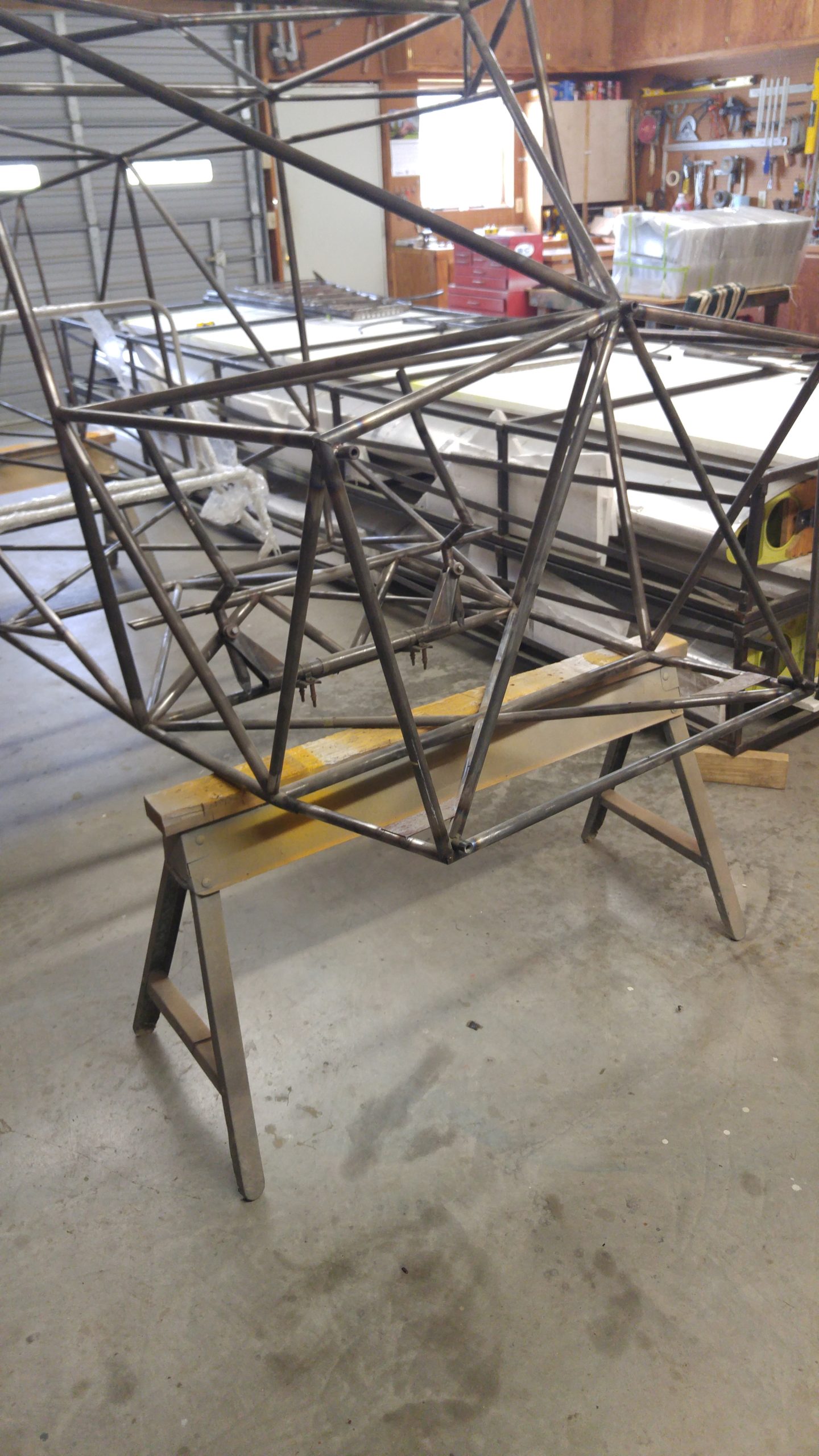
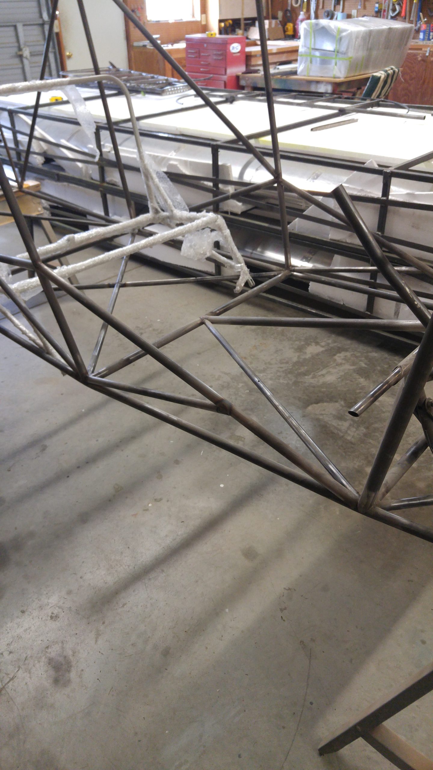
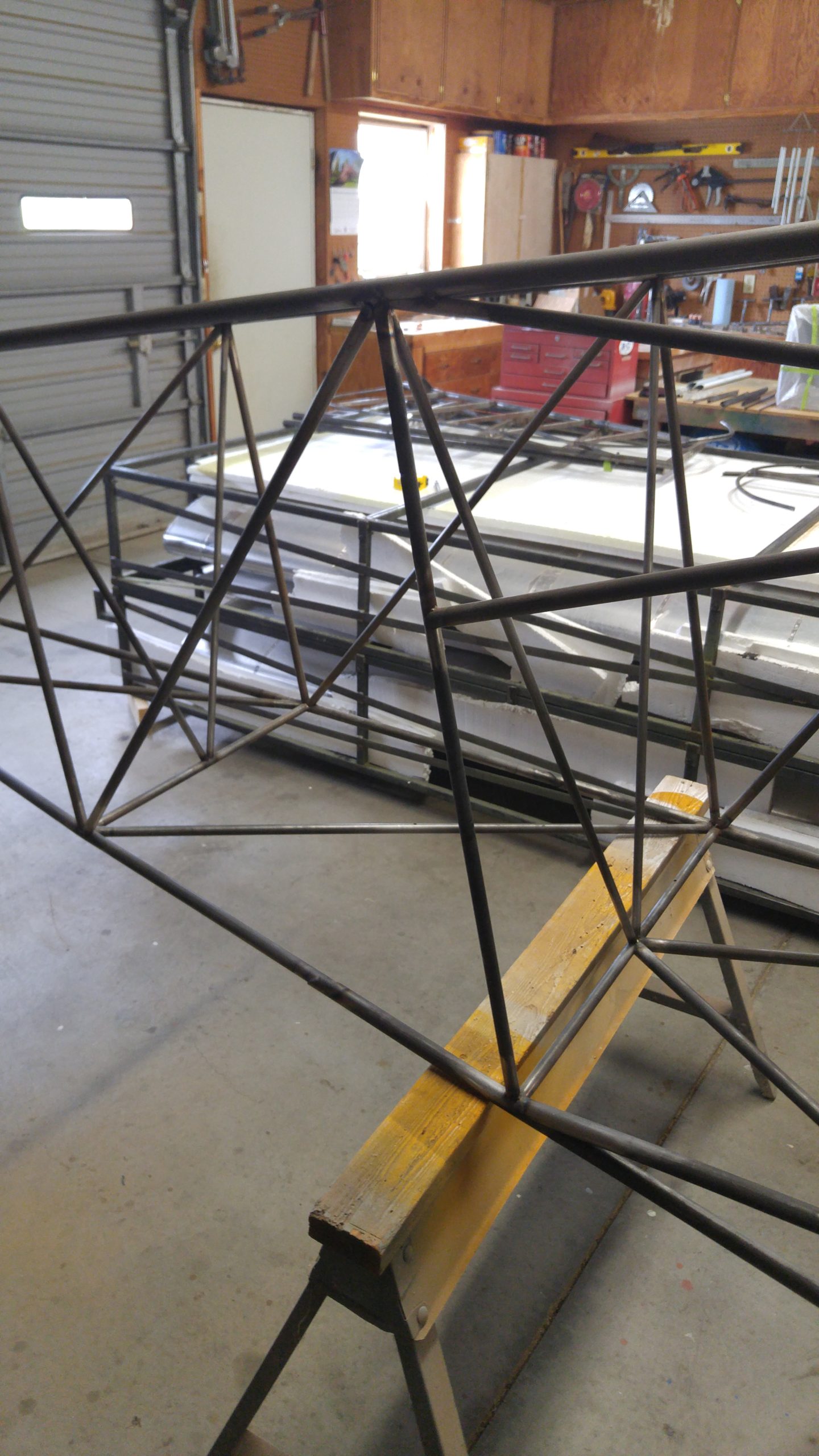
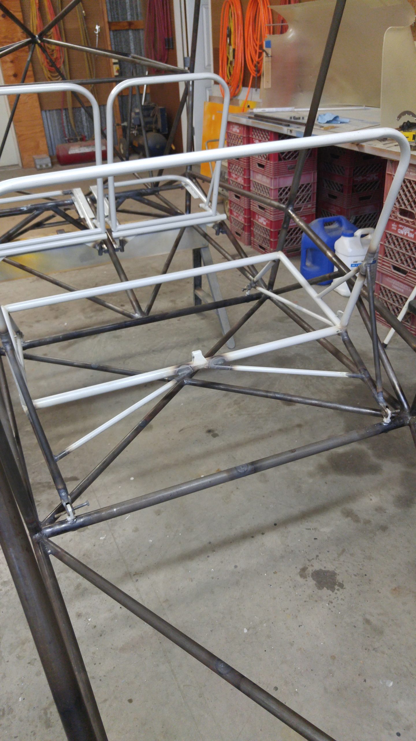
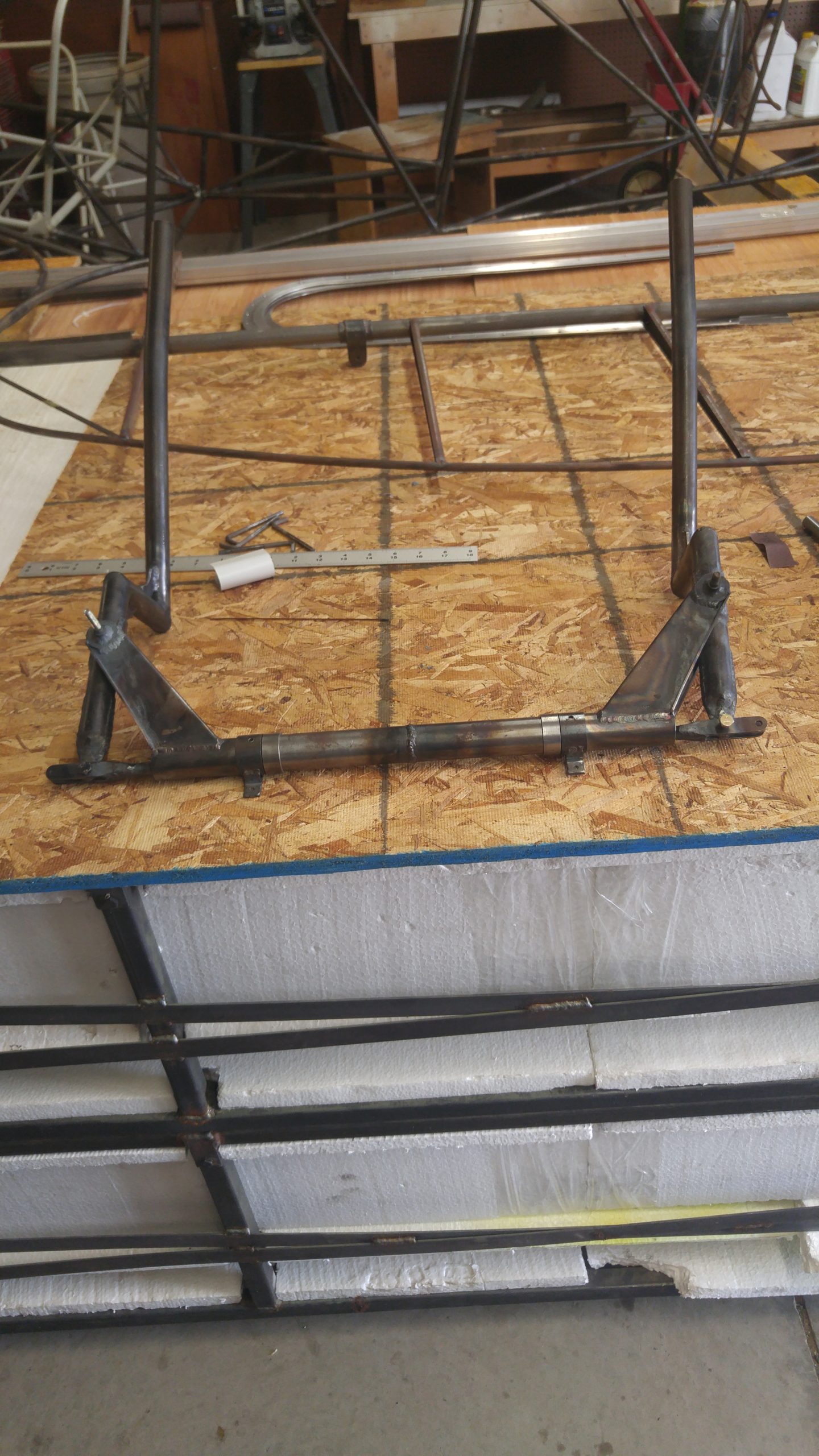
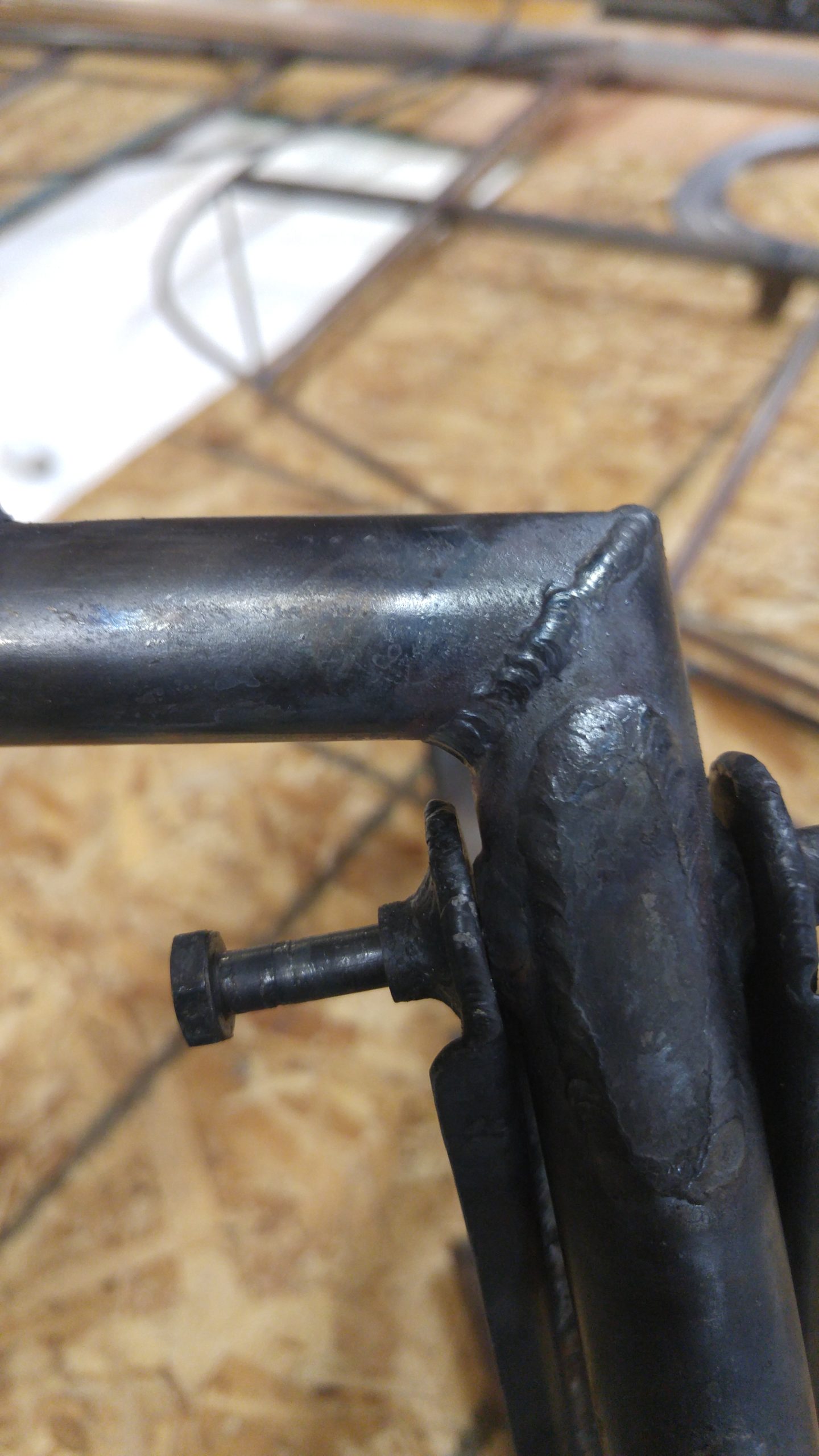
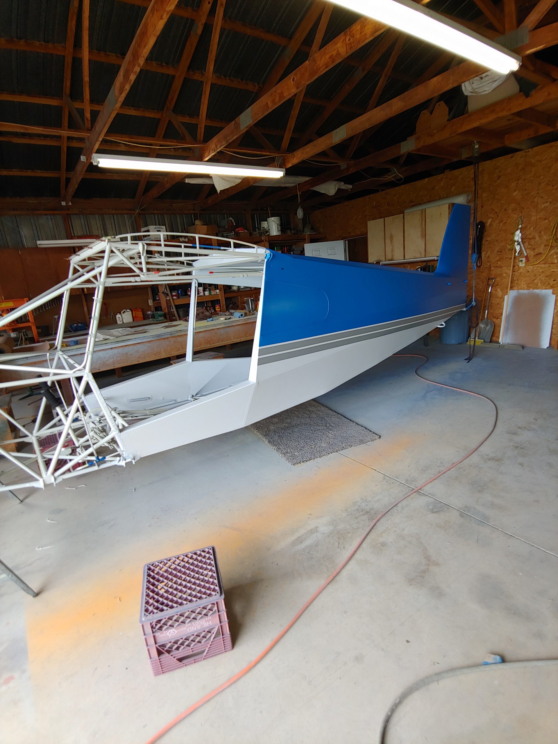
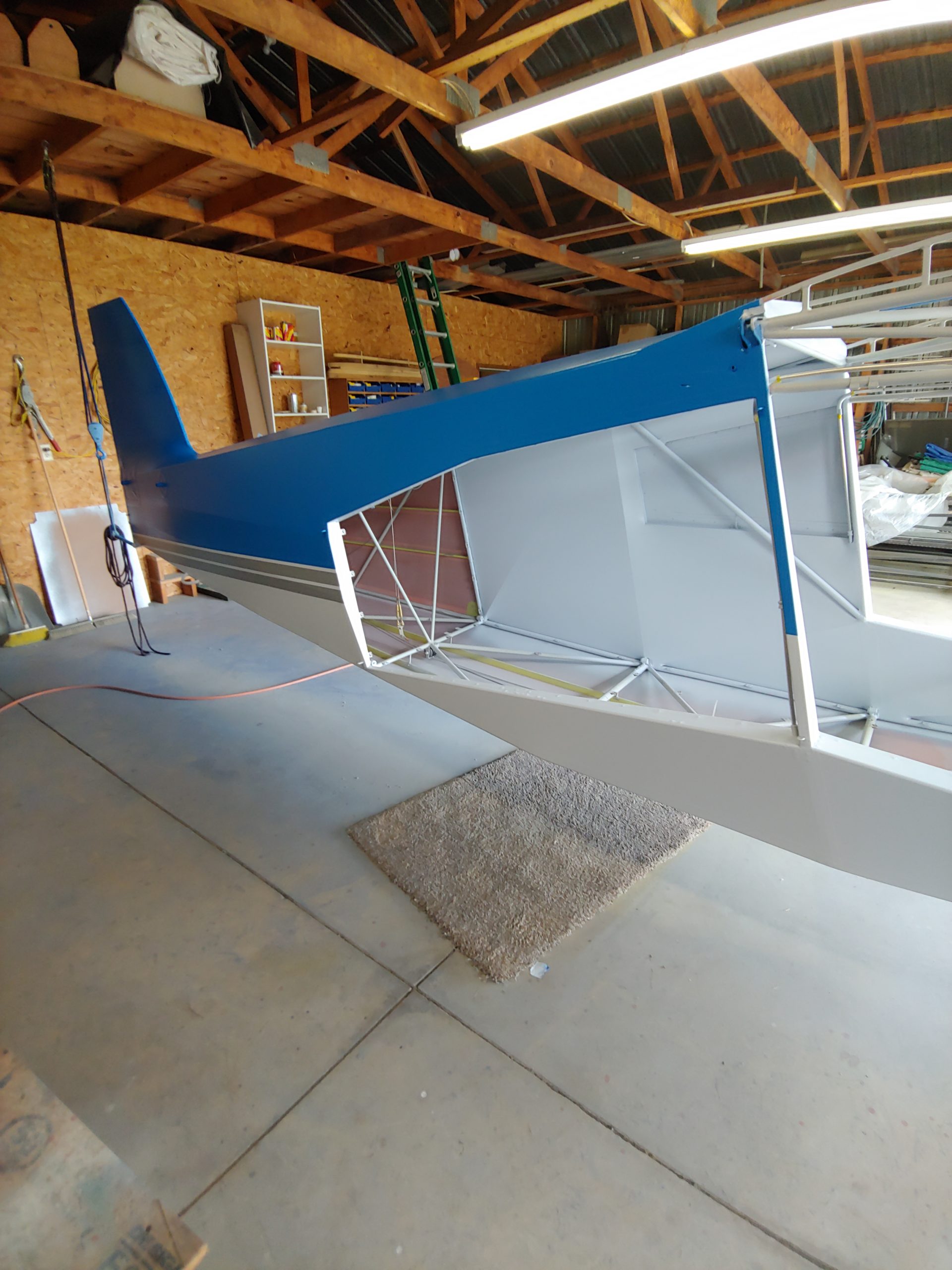
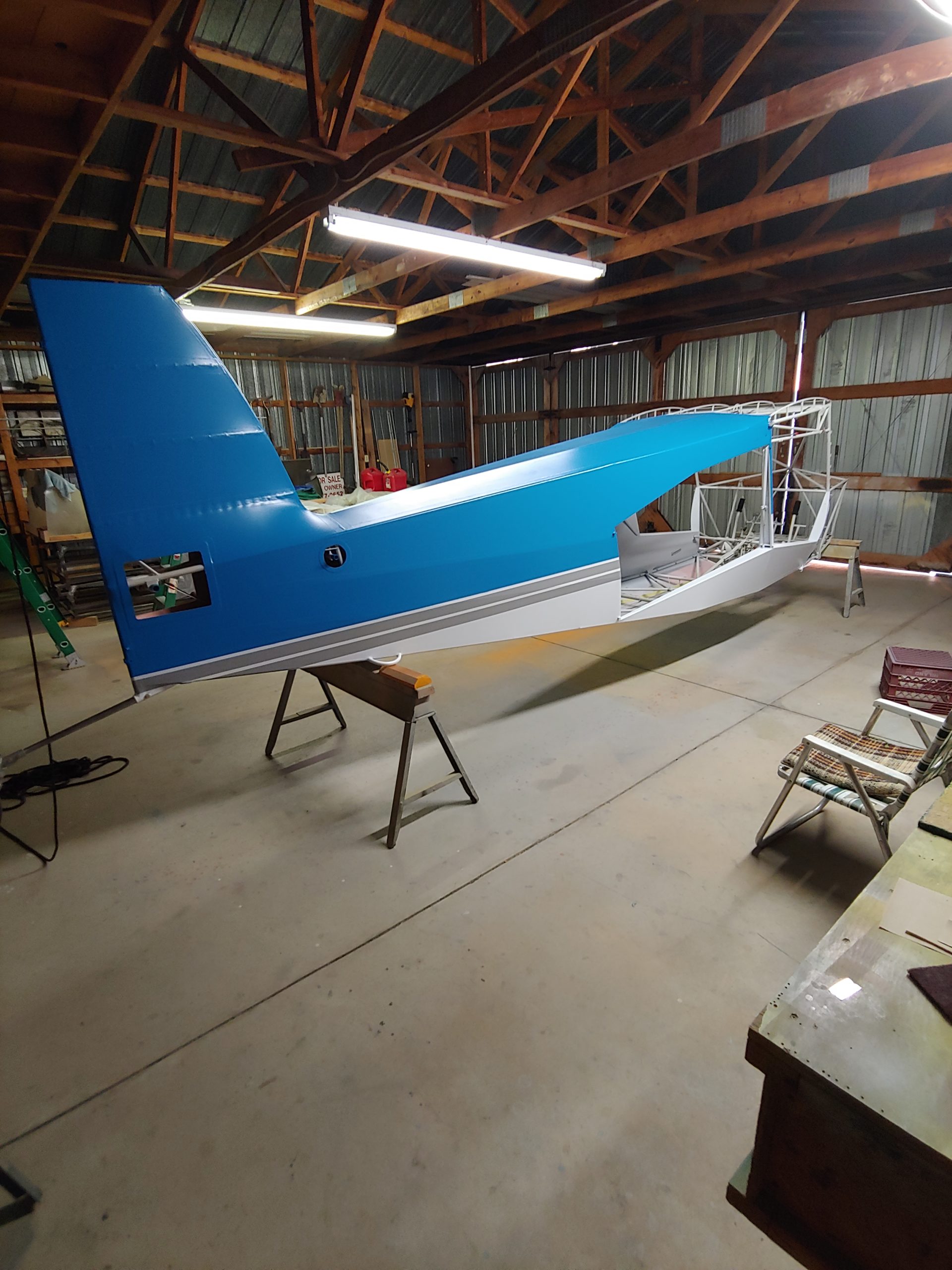
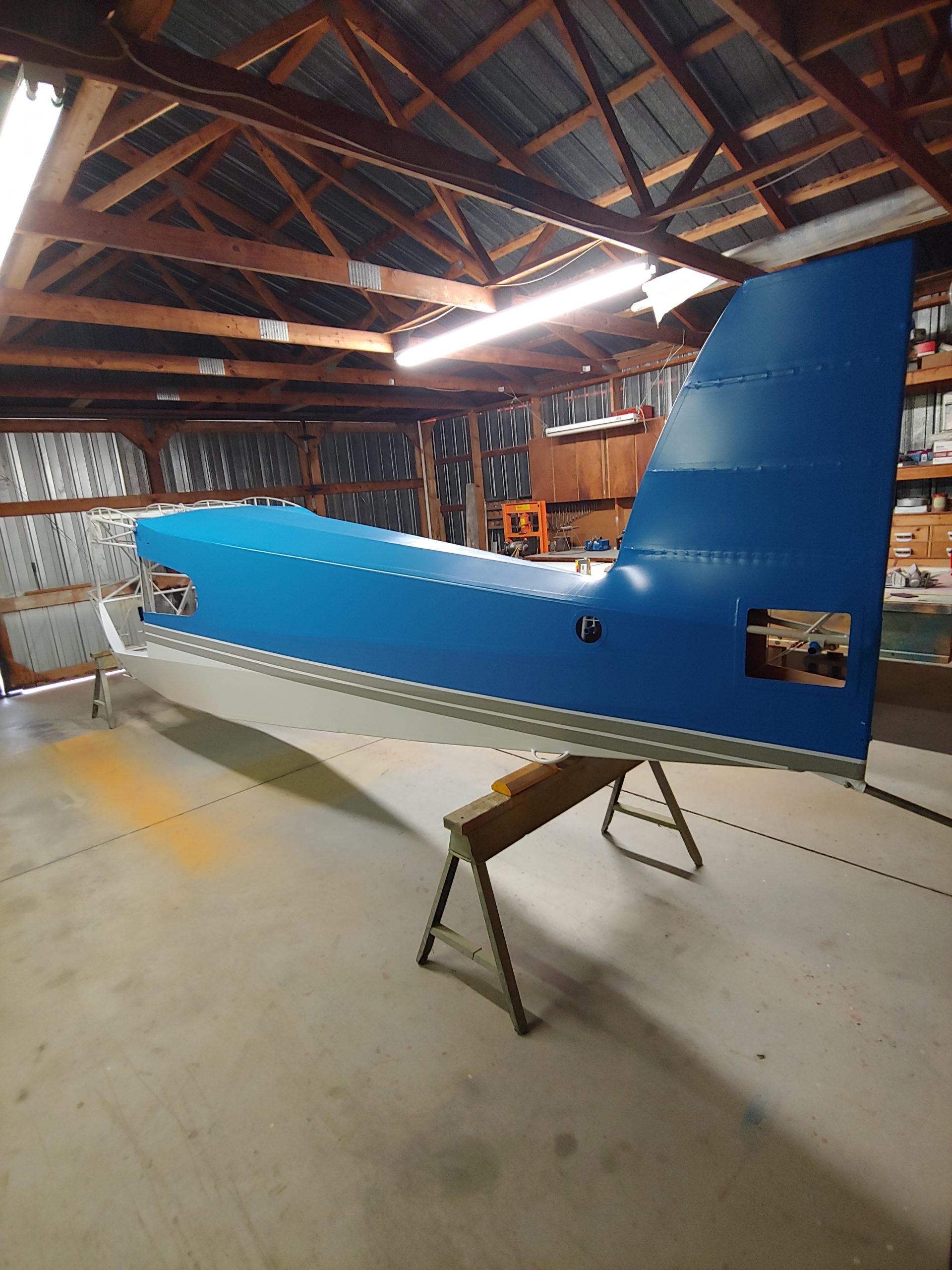
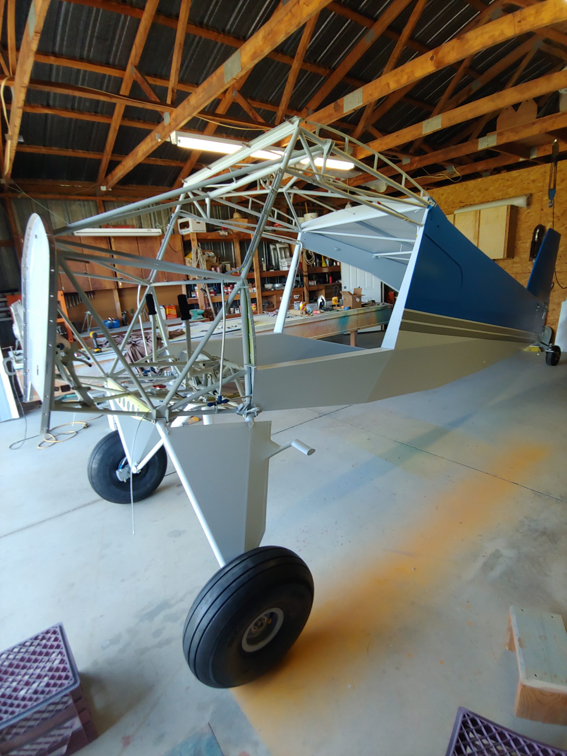
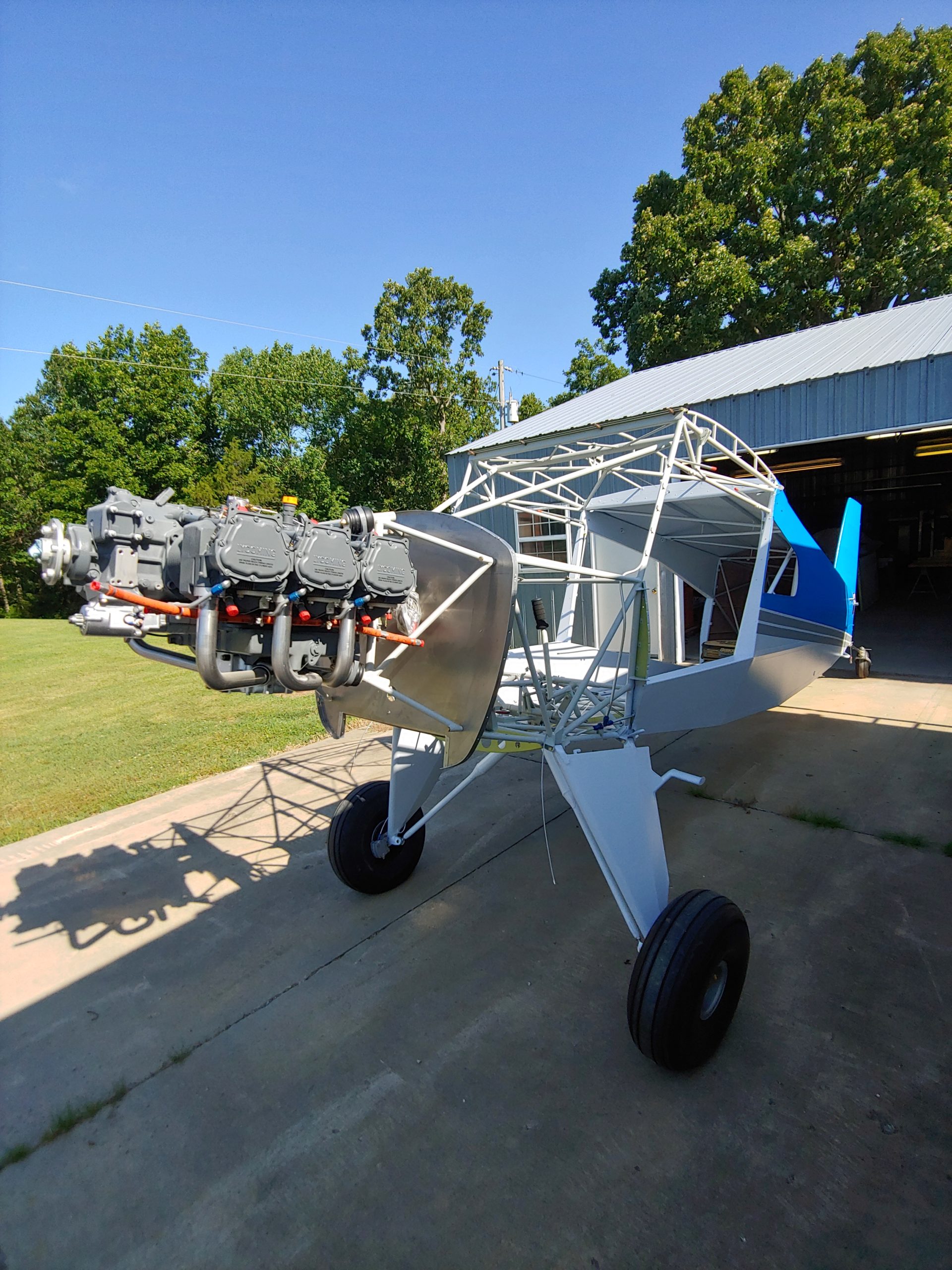
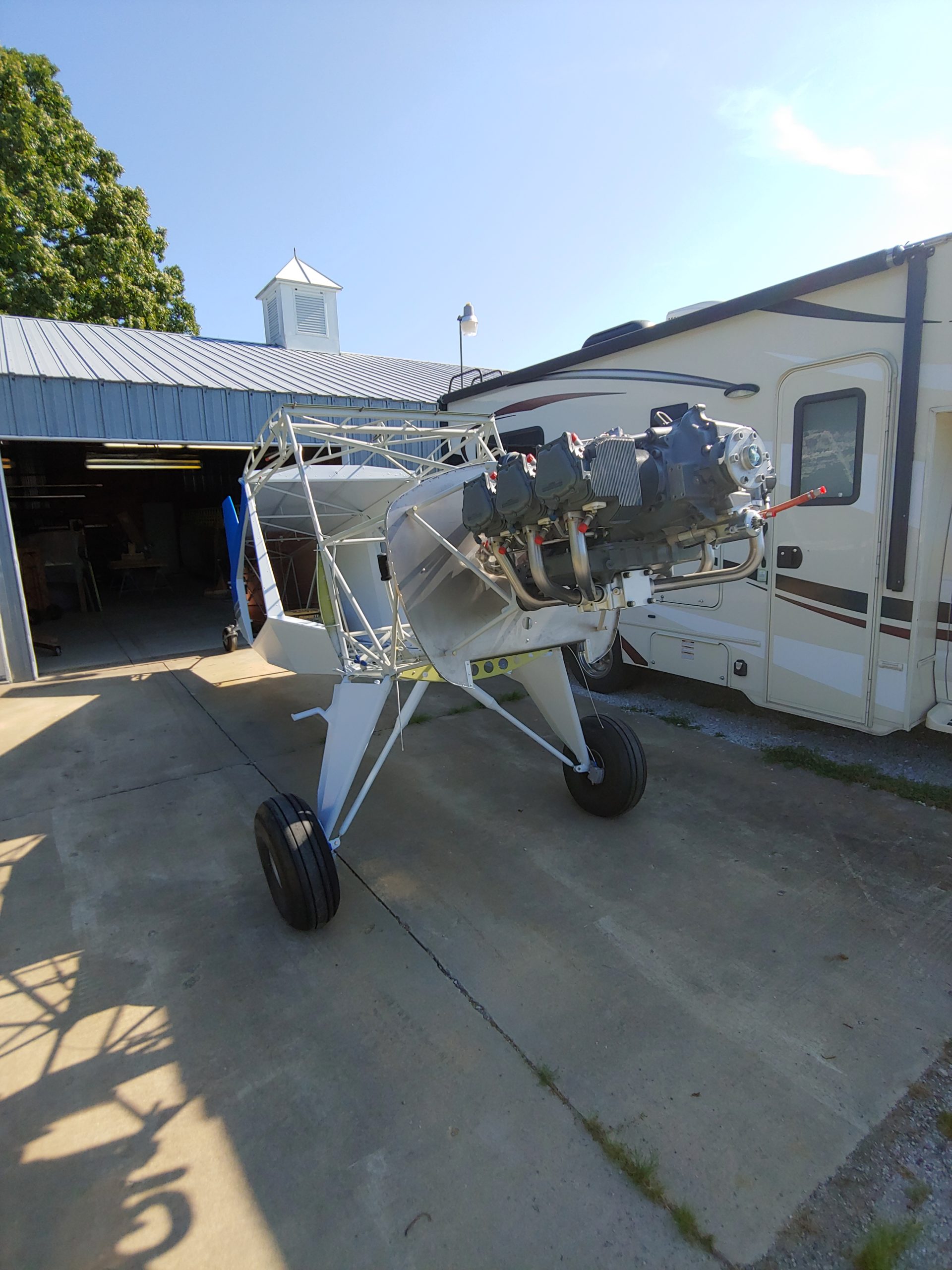
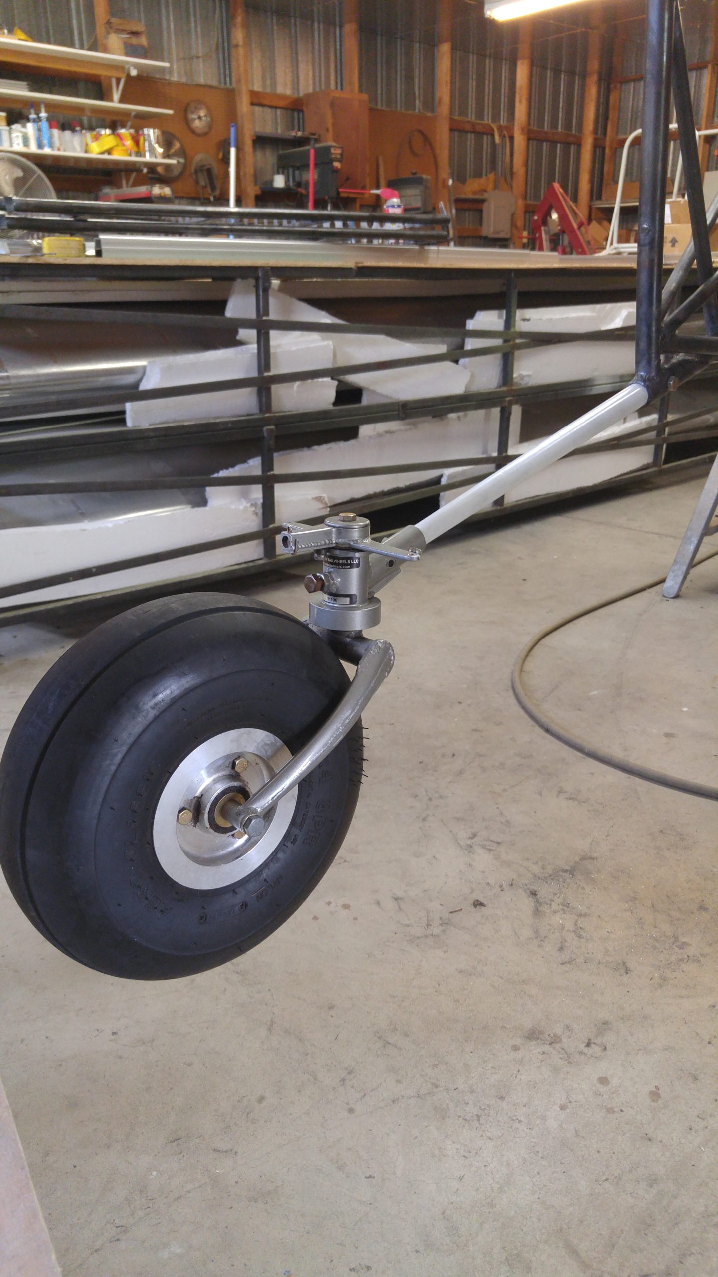
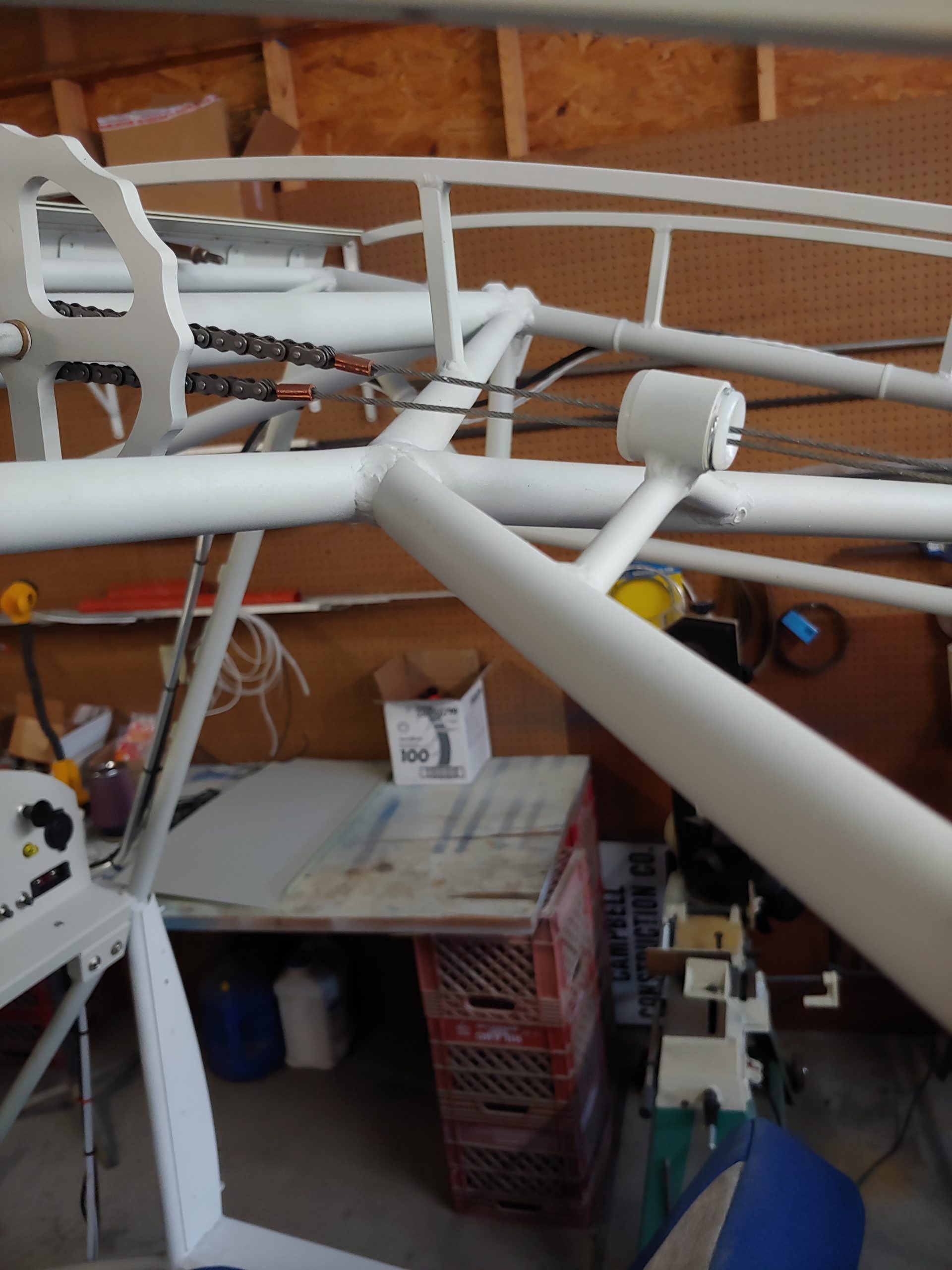
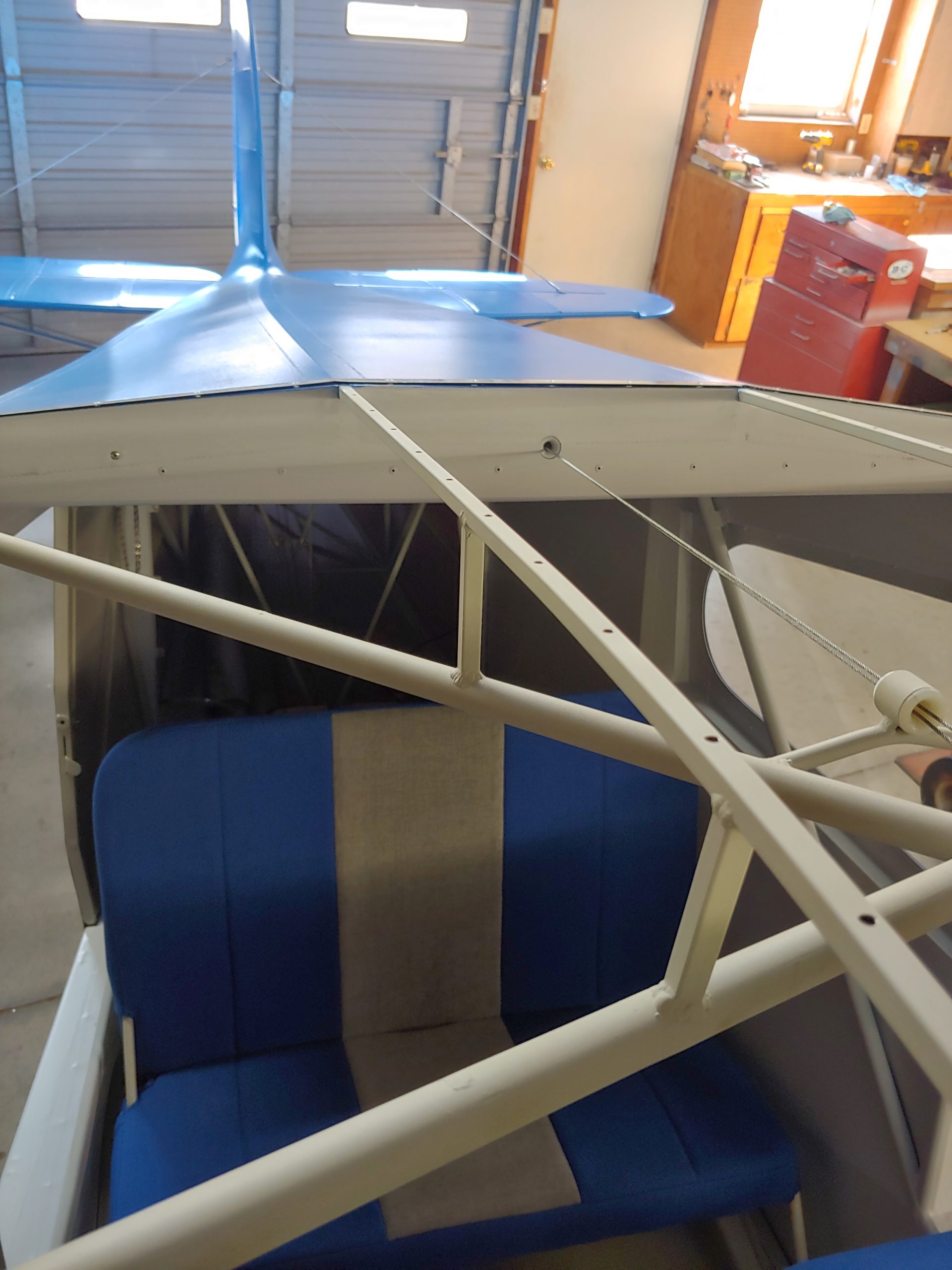
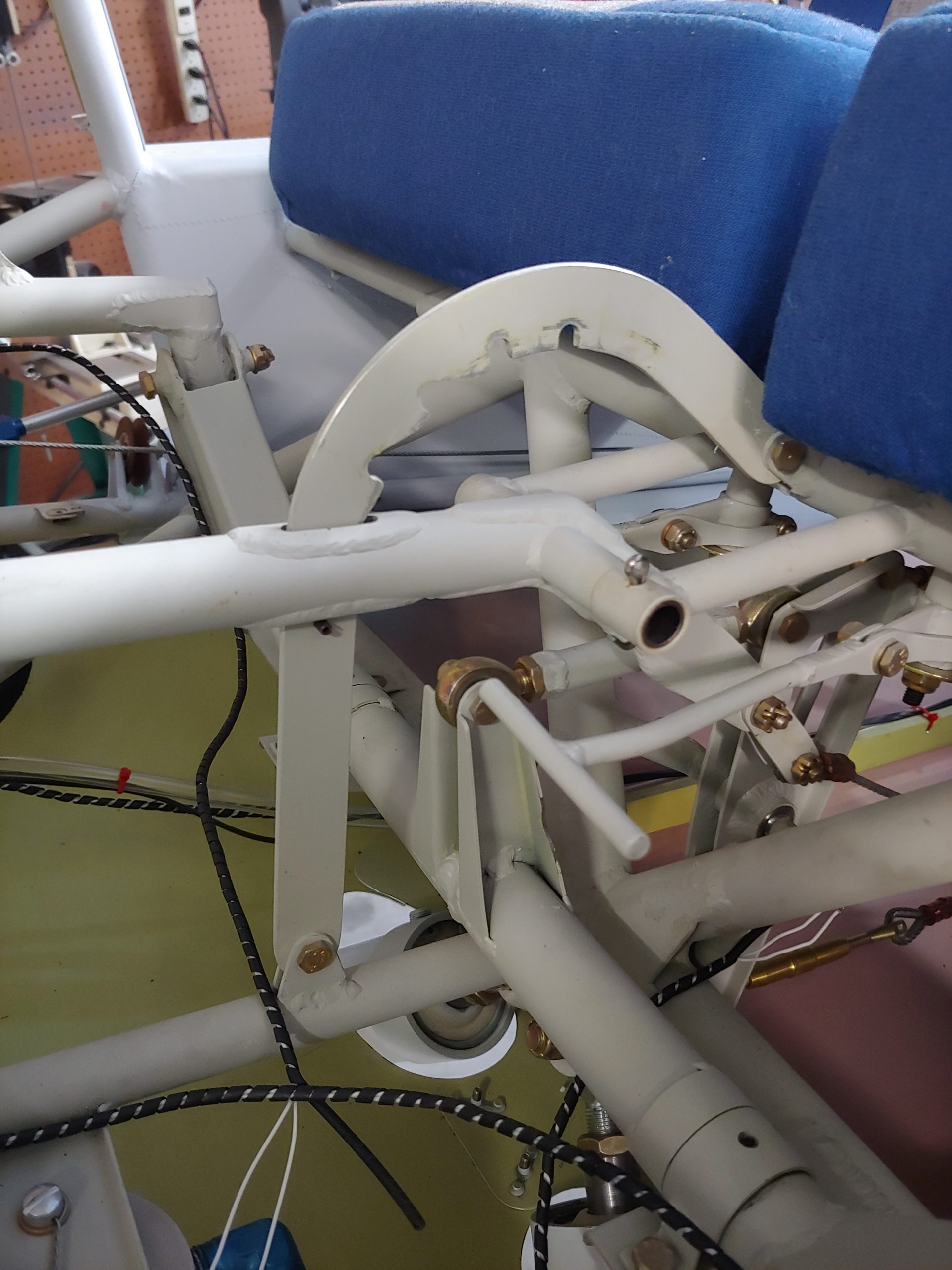
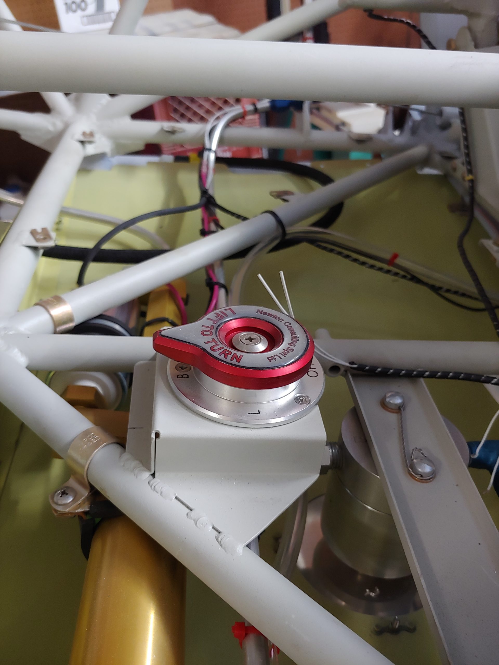
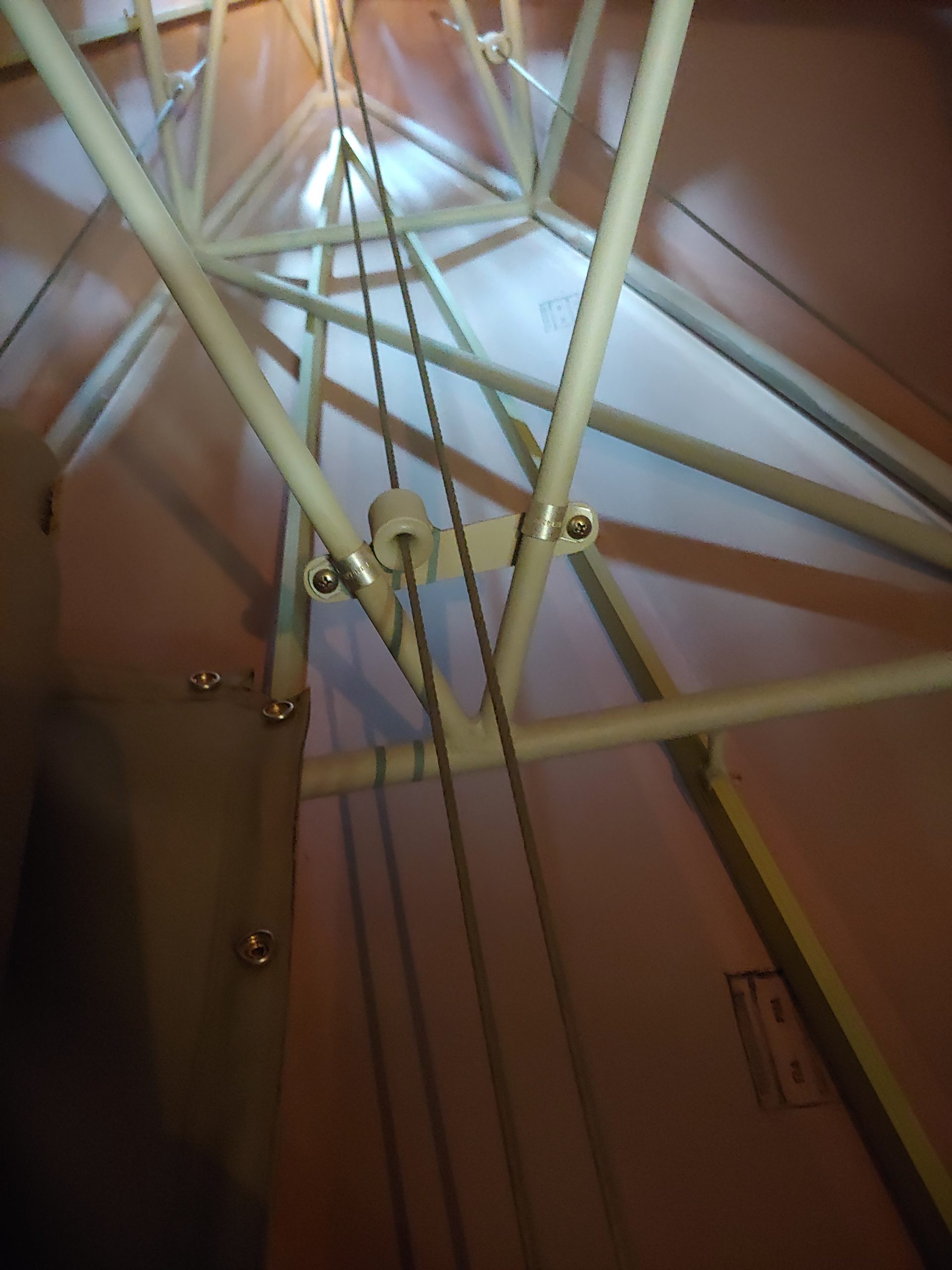
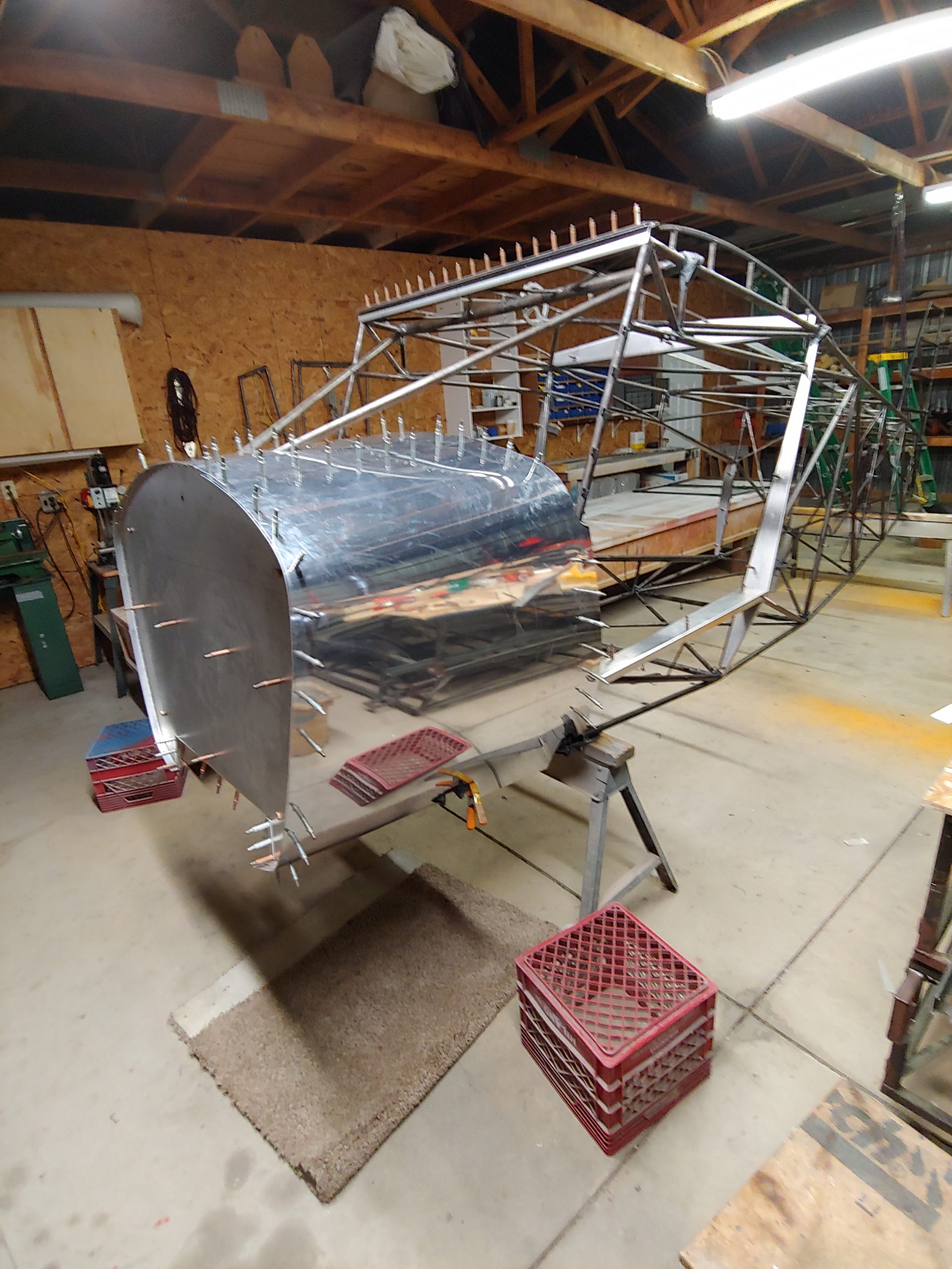
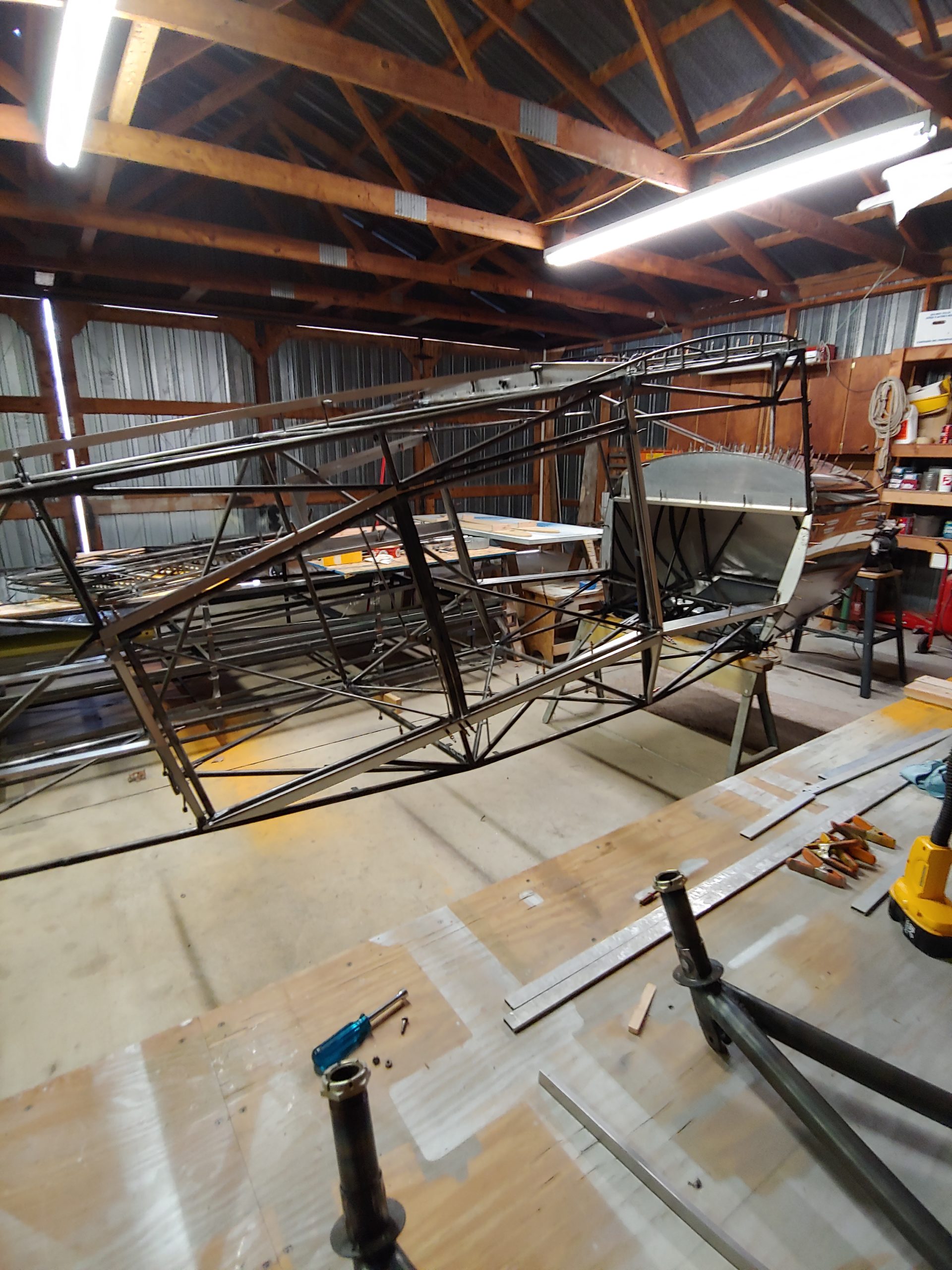
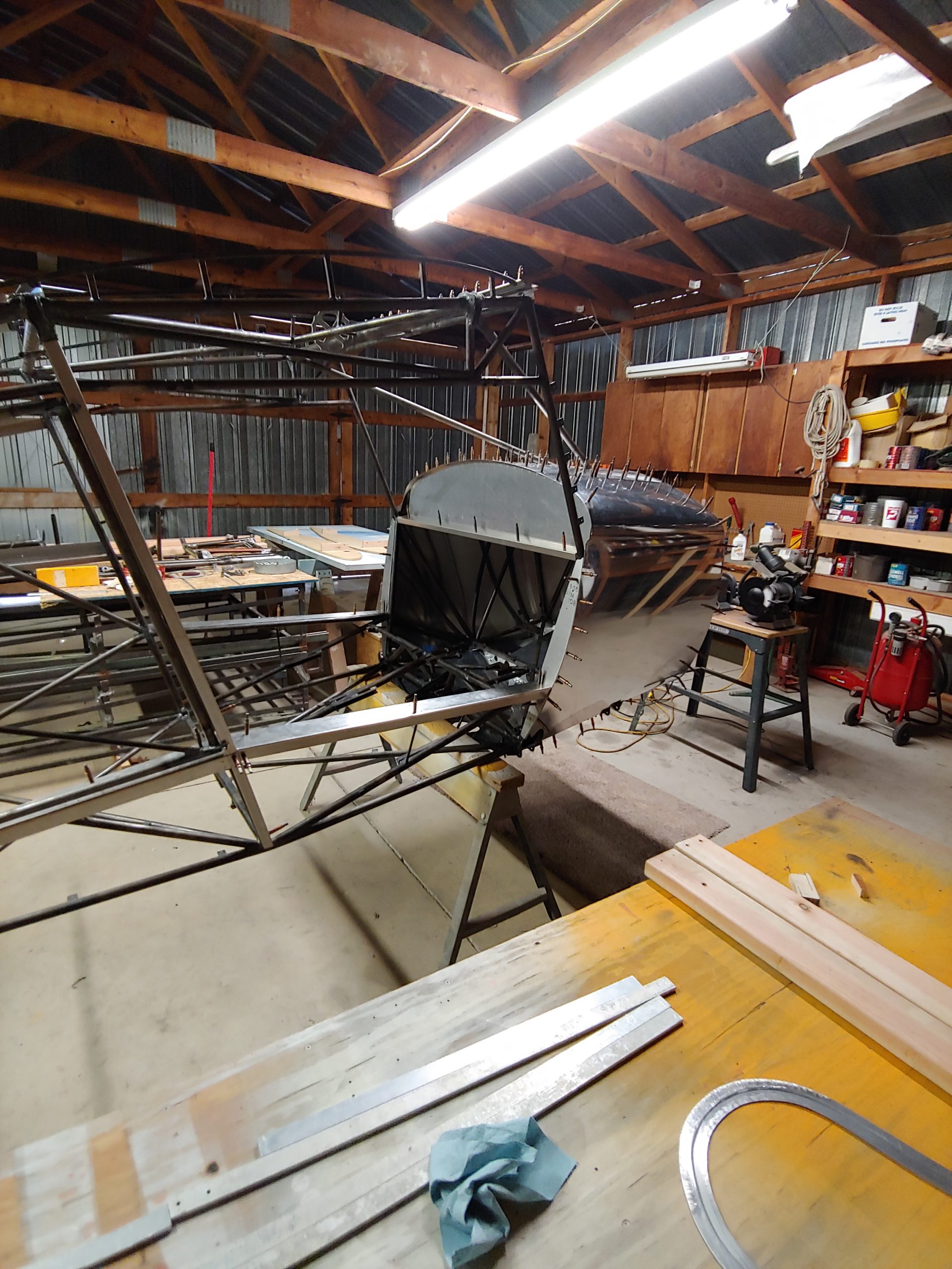
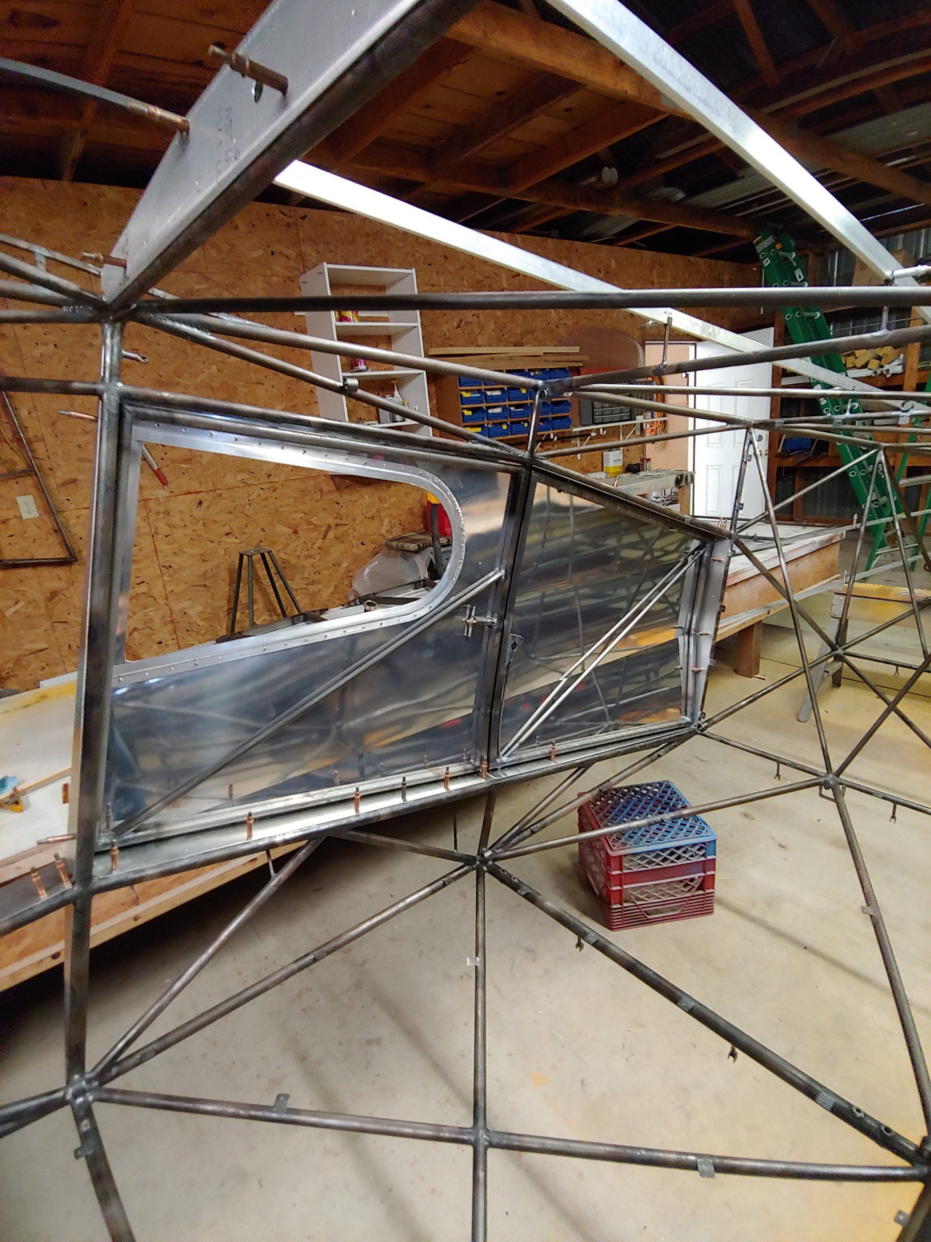
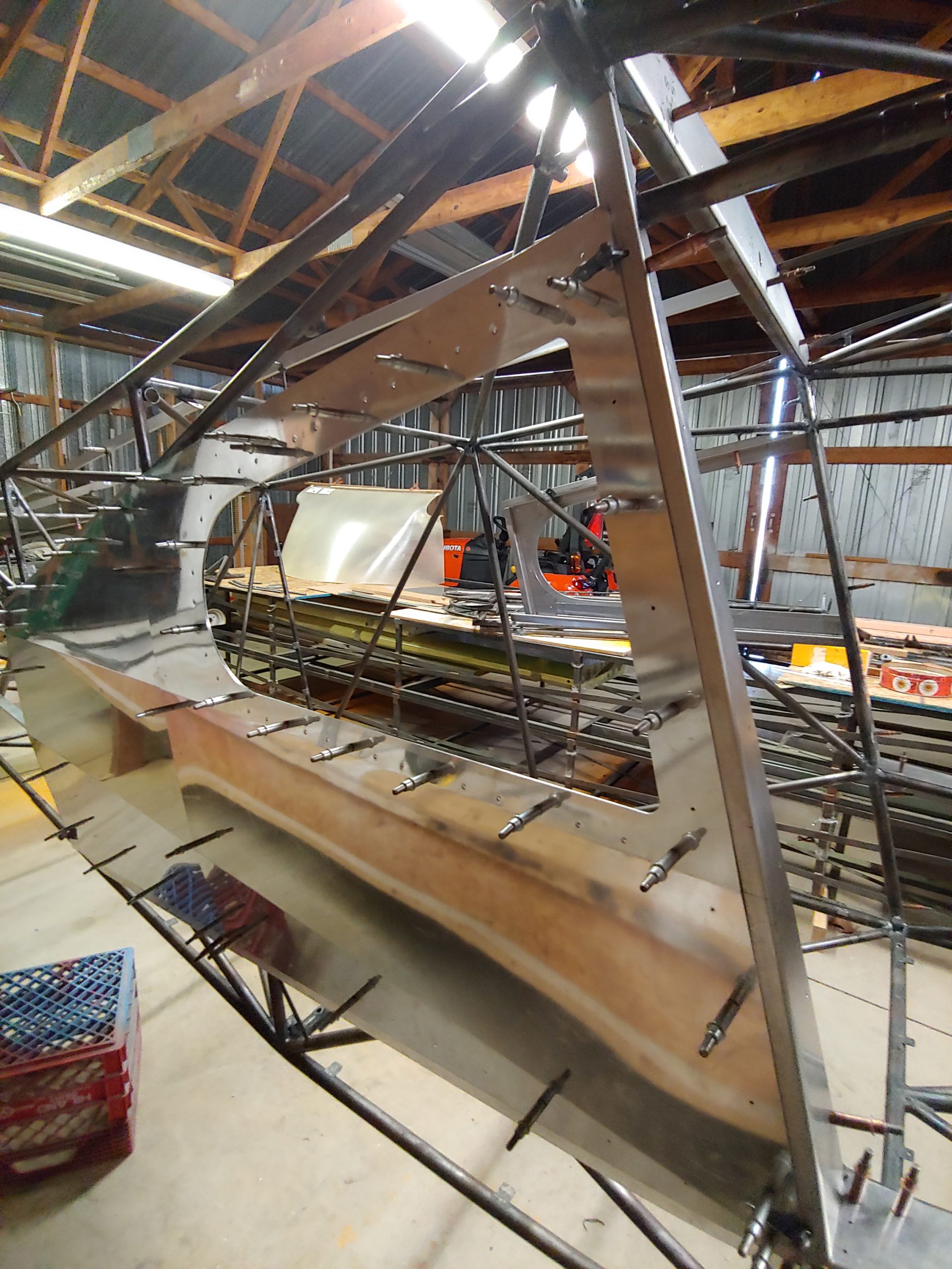
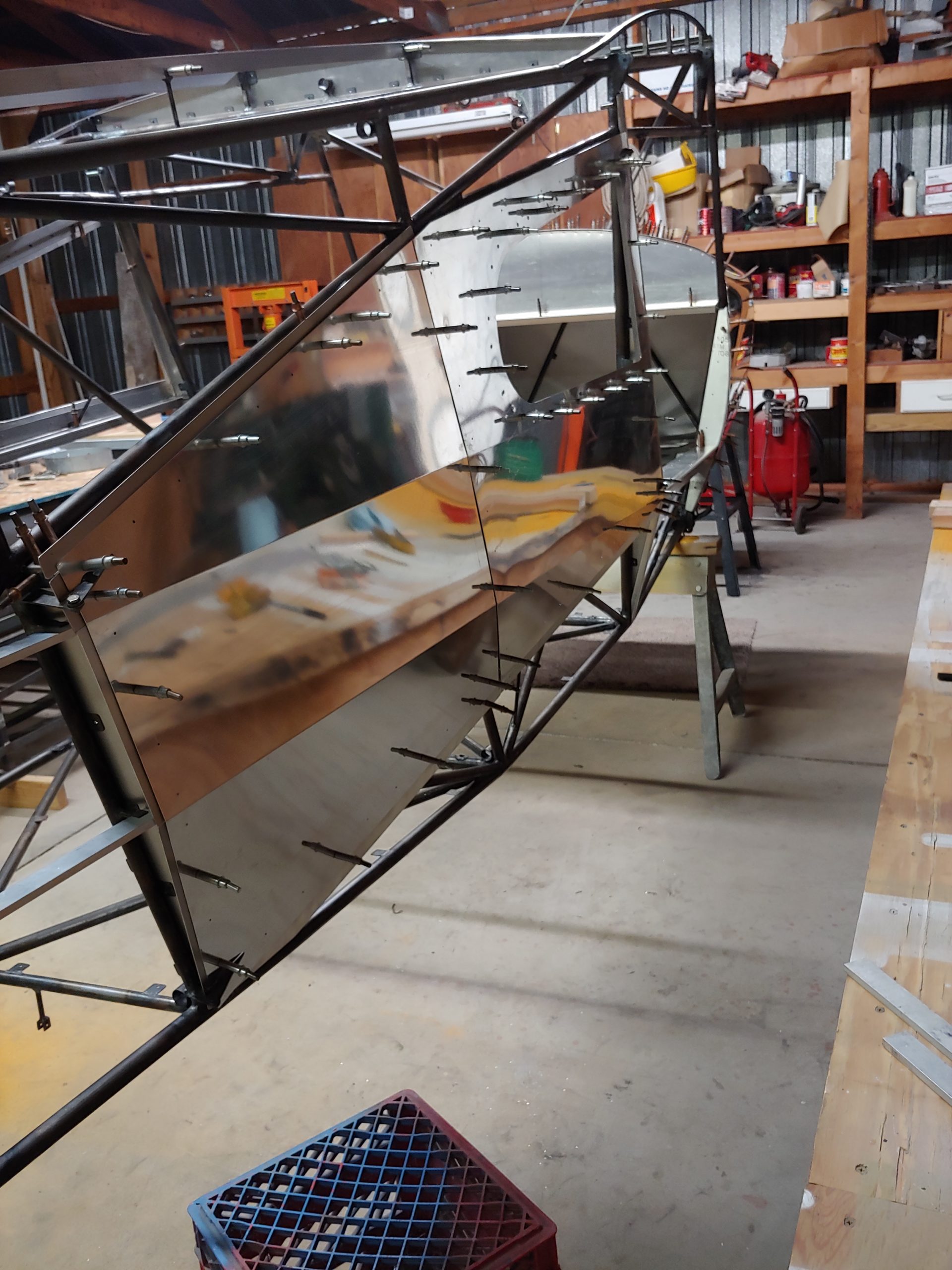
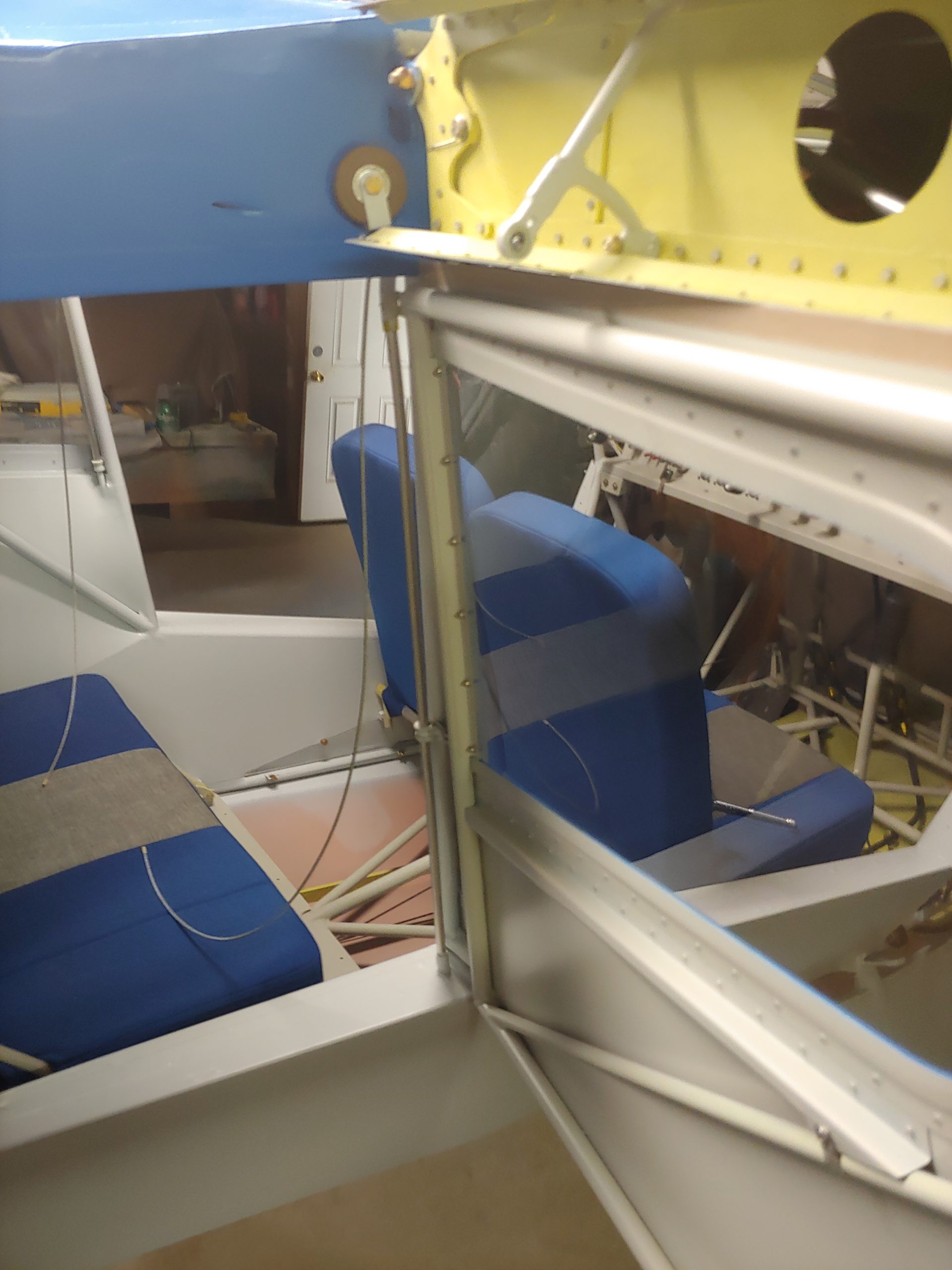
Pictures from Collin of construction and Rollie’s flights:






A Bearhawk Autopilot Success Story
Source: 2019 Q4 Beartracks, Russ Erb
This article is a requested response to Jared Yates’ article in the Second Quarter 2019 Beartracks, where he wrote about his dissatisfaction with his autopilot installation and its subsequent removal. His article left me with the concern that many would read it and come to the conclusion that an autopilot cannot be successfully installed in a Bearhawk. I say it can.
Bearhawk #164 “Three Sigma” has had an autopilot in it since it was first flown over 10 years ago, and I have been very satisfied with it. It is a great workload reducer in cruise, and especially for instrument flight. It did take some development work, though, and does come with limitations. If you understand the limitations and can live within them, then it will greatly increase the value and usefulness of your airplane.
Expectation Management and Adverse Yaw
Knowing Jared and having read his article, I think the difficulties that he had were twofold. The first difficulty was high expectations, brought on by daily exposure to highly capable autopilots, with various climb and descent modes. This can be addressed simply by reducing your expectations. My autopilot will follow a track, follow a GPS flight plan course, and hold altitude. That’s it. Even without all of the vertical modes (I hand-fly those), these capabilities are still well worth the installation.
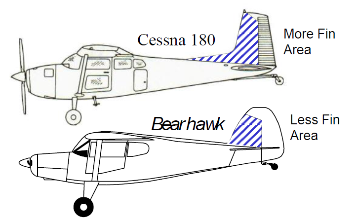
The second difficulty arises from dealing with adverse yaw. I did find a simple and workable solution to this. As Jared wrote “The airplane just flies along uncoordinated, not getting any closer to the desired heading or bank.” I think what he was seeing arose from relaxed directional stability. Shortly after completing my Phase I testing, I invited a Cessna 180 pilot who is also a graduate of the USAF Test Pilot School to fly in my Bearhawk. One of the first things he commented on was that the directional stability was very low. He went on to say that this did not surprise him, since all of the airplanes that looked similar to the Bearhawk (mostly from the 1930s era) also had low directional stability. If I look at a side view of the Bearhawk, it does strike me that the vertical tail is rather small. Compare it to what you see on a Cessna 180. It is even smaller if you imagine that the rudder is not there. More on that in a minute.
In the early years of flying Three Sigma, I noticed that a little bit of turbulence would cause the ball (inclinometer) to swing from side to side, and as it did, the autopilot would bank this way and that to try to stay on the commanded track. If the turbulence was too bad (and that didn’t take very much), I would have to disengage the autopilot and hand fly the airplane. This sort of defeated the point of having an autopilot.
Increasing Directional Stability
On the way home from Oshkosh 2011, I stumbled onto a partial solution to the adverse yaw, which was to simply to hold my feet on the rudder pedals and prevent them from moving. If I tried to actively center the ball in response to the autopilot inputs I would rapidly find myself in a Pilot Induced Oscillation (PIO). Just holding the pedals still, however, made a big improvement.
Why did this help? The amount of adverse yaw seen is caused by the relative sizes of the yawing moment caused by deflecting the ailerons and the amount of directional stability. Just to review, adverse yaw is the name for when you put in left stick to roll left, and the airplane rolls to the left but the nose swings to the right, causing a sideslip. This is caused because the downward moving aileron (right) causes more lift and thus more induced drag. The upward moving aileron (left) causes less lift and thus less induced drag. The difference in the induced drag pulls the nose to the right. This is why your flight instructor taught you that you had to use coordinating rudder when rolling in or out of turns, to compensate for adverse yaw.
If the directional stability is strong, such as in a Cessna 180, the adverse yaw moment from the ailerons is overwhelmed by the large restoring moment of the high directional stability. Thus, if we could increase the directional stability we could reduce the impact of the adverse yaw.
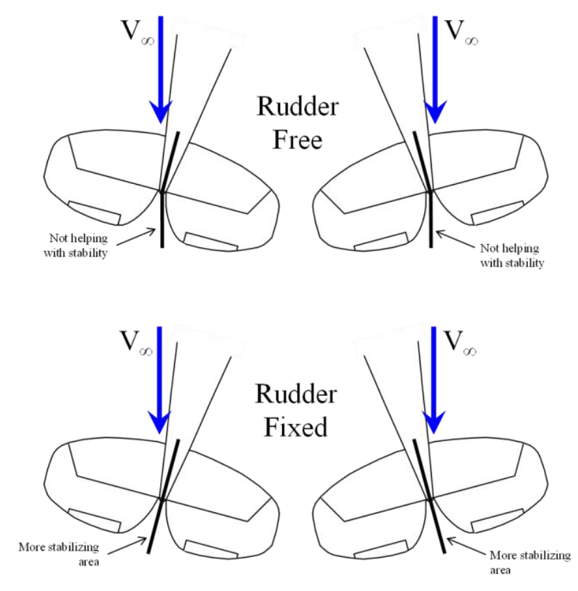
The key issue here is the difference between rudder free and rudder fixed stability. In rudder free stability, your feet are off the rudder pedals, and the rudder is free to flop to one side or the other as sideslip increases. When the rudder flops, it isn’t providing much stabilizing moment. In fact, while not absolutely accurate, it is useful to think of it as a flopping rudder provides no stabilizing moment, so if your feet are not on the pedals, it is as though the rudder isn’t there. Take another look at the side view of the Bearhawk and imagine the rudder is gone. There are hardly any feathers on that arrow to keep it pointed in the right direction!
If the rudder, however, is fixed, then it remains aligned with the vertical fin, and all of the area of the rudder is now available to help stabilize the airplane directionally, which then reduces the effect of adverse yaw. This is what happened when I held rudder pedals.
To be able to use the autopilot without having to hold the rudder pedals, I needed a way to increase the rudder free stability. Adding more vertical surface, such as a ventral fin, was not a good solution as that would reduce the amount of sideslip that could be commanded when I wanted it. A better solution was to find a way to make the rudder less “floppy”.
The rudder pedals are attached to the fuselage frame with springs. Many people think that these springs are there simply to keep the rudder pedals from falling toward the pilot. While that is true, they also provide a method to stiffen up the rudder.
The original springs I installed on my rudder pedals had a spring constant of 2 lb/in. That means it took a force of two pounds to stretch them one inch. I searched for the strongest springs I could find that were the proper length at the shortest required extension and were able to stretch to the required maximum length. The springs I found had a spring constant of 5 lb/in. This stiffened the rudder noticeably and greatly reduced sideslip (ball swings) in turbulence, allowing autopilot usage with no feet required under most normal conditions. This passively improved directional stability, providing what I believe Jared was trying to do actively with the third servo.
My Autopilot Installation
I had always planned for an autopilot, having seen the workload reduction possible while flying in a friend’s Cessna 180 from California to Florida for Sun n’ Fun 1999. At the time, only certified autopilots were available, so I designed a servo mount for the right wing to use an S-Tec servo with a capstan to connect to the aileron cable. Between the time I designed that mount and when I was ready to install an autopilot, many other options became available, and these were significantly less expensive. I selected the TruTrak ADI Pilot II autopilot (don’t consider this a recommendation, because while TruTrak will still support the ADI Pilot II, it is no longer offered for sale). Fortunately, I was able to adapt my existing wing servo mount to the TruTrak servo. While my panel includes two Dynon D-10A EFIS units, I did not use the Dynon autopilot because it was not released until after my airplane was already flying with the TruTrak unit.
I used capstans on the aileron cable and elevator cable because that was what I was familiar with. Later Cal Brubaker worked with TruTrak to design an installation using pushrods, shown on Bearhawk CD. This was essentially the installation that Jared used. If I was building now, I would use the pushrod system as it is simpler and more compact.
Tuning The Autopilot
After installation, TruTrak provided instructions to adjust several values controlling the system, to include the gains (sensitivity) of the lateral and vertical response. Since this was the first Bearhawk installation I knew of, there was no guidance on setting the gains. Therefore, I arbitrarily set some numbers, which turned out to be way too high. The results were good in smooth air, but it became very twitchy and unusable in any amount of turbulence.
The TruTrak representatives gave the best answer they could on adjusting gains. They agreed from my description of how the airplane was flying that the gain was too high. They recommended that I reduce the gain until the “autopilot flies like you do”. I reduced the gains twice, keeping records of what they had been and what they were now. One day while I was flying with another pilot, I engaged the autopilot while I was sorting out another issue. We bounced around a little bit in turbulence, but I wasn’t concerned because at some point I was thinking that the other pilot was flying. When I realized that autopilot was engaged, I realized gains were reasonably set.
Limitations
As I mentioned earlier, my autopilot installation will hold a specified track, turn to a track, follow a GPS flight plan course, and will hold the current altitude. While it will make small adjustments to altitude (up or down 90 feet max at a time), the autopilot has no actual vertical modes. Which is to say, it is only useable in the cruise segment of flight. I’m okay with that. That’s all I ever expected it to do.
A few years ago, I noticed a weird but perfectly reasonable response of the autopilot. While flying through sink (downward moving air), the autopilot would command a pitch up to stop the loss of altitude. As the speed slowed, it would command more pitch up. As the angle of attack on the propeller disk increased, the P-factor increased and would cause the nose to yaw to the left. This would start a yaw rate to the left, which the autopilot would respond to by banking right. Thus, I’m flying along and find myself slow on airspeed in a weird nose up sideslip to the right. The solution was simply to disengage the autopilot, hand fly out of the sink, and then re-engage the autopilot.
When I started training for an instrument rating, we tried getting the autopilot to fly the approaches, but when we slowed to approach speed (using 75 KIAS), the higher angle of attack and P-factor from the prop became a problem. The P-factor would yaw us to the left, at which point the autopilot would bank to the right. The reduction of lift would cause the nose to drop and swing back to the right. The loss of altitude would cause the autopilot to pitch the nose up, and the cycle started again. So here we were in some sort of autopilot-induced Dutch Roll-like motion. I tried to tame it by actively using the rudder to keep the ball centered, but that turned out to be a higher workload than simply hand flying the airplane. Thus, I accepted that I have to hand fly the final portion of the instrument approach.
Benefits of an Autopilot
The major benefit of the autopilot is reduced workload in cruise. If you are only flying a half hour to your favorite breakfast stop, this is no big deal. If you have another qualified pilot, you can reduce your workload by having the other pilot fly. On the other hand, if you are the only qualified pilot on board, flying five legs over two days for 15 hours of flight time to get to Oshkosh (yes, I’ve done that), then having an autopilot can significantly increase the probability of a successful outcome.
For instrument flying, especially single pilot IFR, the autopilot can be a huge workload reducer. Yes, mine won’t fly the approach legs, but it will do an amazing job of flying the enroute legs. Even in training, I will engage the autopilot at cruise conditions between practice approaches while I am programming the GPS, setting up the approach, getting ATIS, and generally getting my act together. These are very difficult to do if I simultaneously have to fly the airplane, but are very simple if I can hand the airplane over to another pilot, in this case “George”.
Daryl Rhodes Flies his New Bearhawk LSA N367G
Source: 2019 Q4 Beartracks
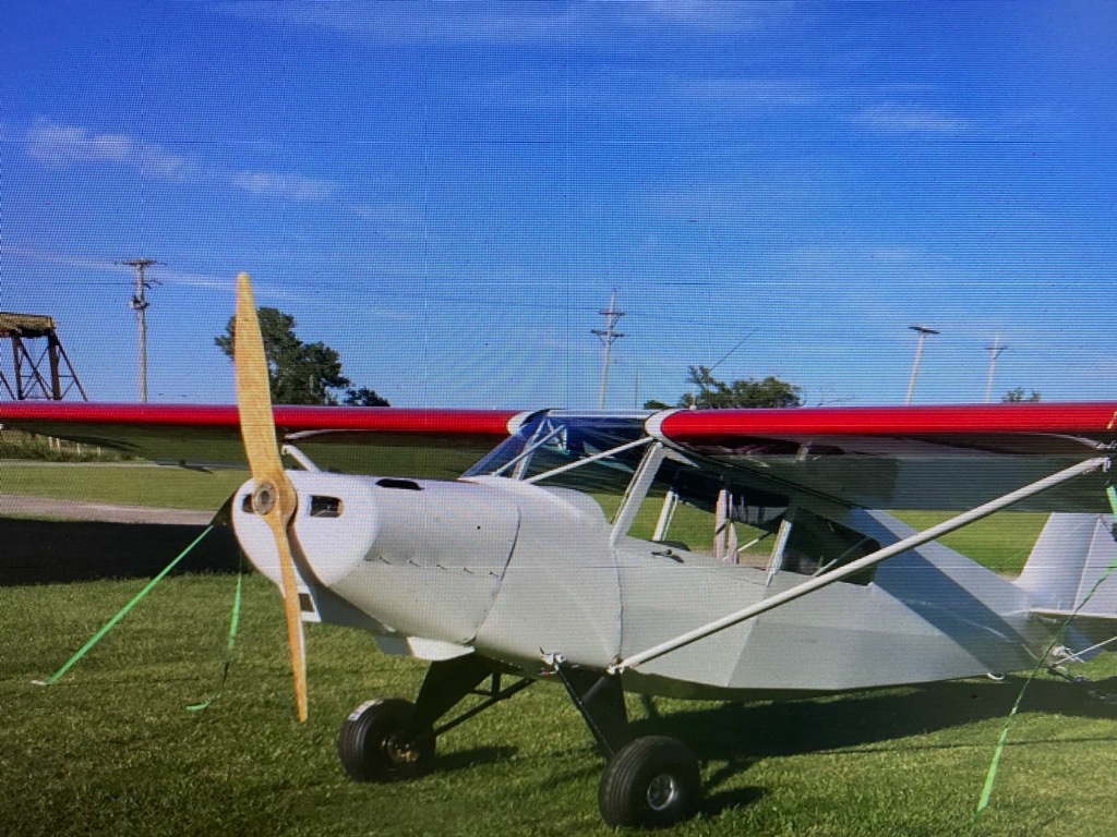
Building a homebuilt airplane is always a large achievement. Daryl built his new LSA in 2.5 years, without a kit! Well, it really took two years of construction, but it took a little while to get all of the paperwork and such done. He used the Stewart covering process, and a “little bit modified” Continental C-90. Empty weight came to Continue reading
Horizontal Stabilizer Struts, Female 5/16″ Threads
A Tale of Two Tail Struts
Source: 2019 Q1 Beartracks, Jared Yates
It was the best of times, it was the worst of times. We had some visitors in town that wanted to go for an airplane ride, so we drove out to the airport and started the usual preparations. Bearhawk folks have known for some time that the airfoil-shaped front support struts for the horizontal stabilizer are a candidate for extra preflight scrutiny. As usual, in my preflight walkaround I grabbed the strut and gave it a tug, but not as usual, the bottom end came off in my hand. The friends were understanding about not getting to go for a ride, or at least they said they were, so I removed the upper bolt still holding the strut on, and went back home.


When the guests were gone I was able to study the broken AN490, which you can see above. This cross section shows that a crack had been developing across the part for some time, with the dull gray part being the section that was holding together at the time of my inspection. Would it have been safe to fly if I had neglected to break it? Probably so. It is said that Bob flew the prototype Bearhawk without the struts before adding them later in testing. It probably would not have broken yet, but it was going to happen sooner or later. At least this was a time of minimal inconvenience.
A few years ago I had contemplated stripping the covering off of the horizontal stabilizer to add wooden strips and give the ribs an airfoil cross section, also adding provisions for an electric trim servo. That project never made it to the top of the to-do list, but since that mod leads to a reduction in the incidence angle, it also requires longer tail struts. This meant I had a pair of spare AN490s on hand, so my plan to fix this was to weld a new one in place of the broken one and carry on.
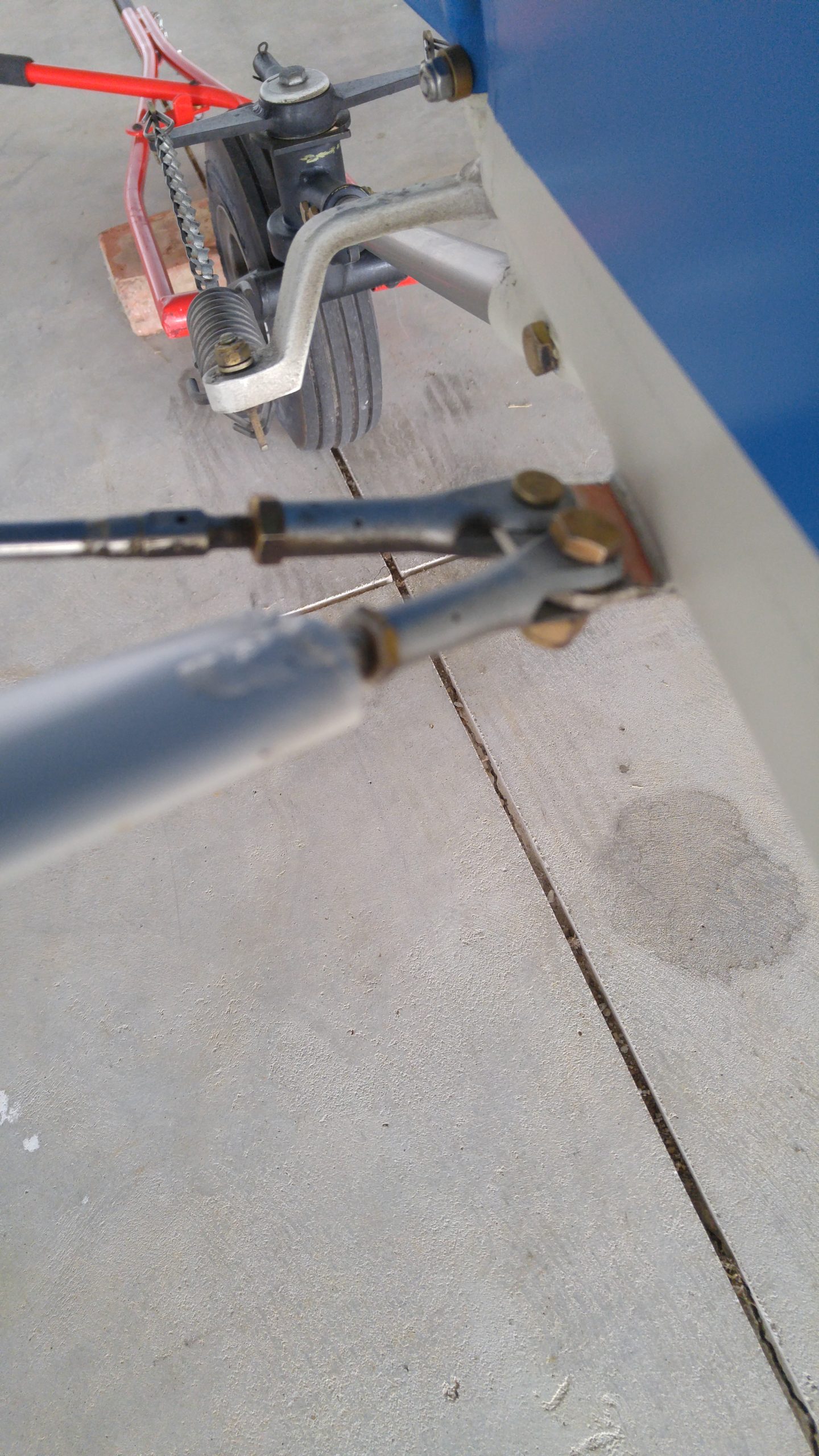
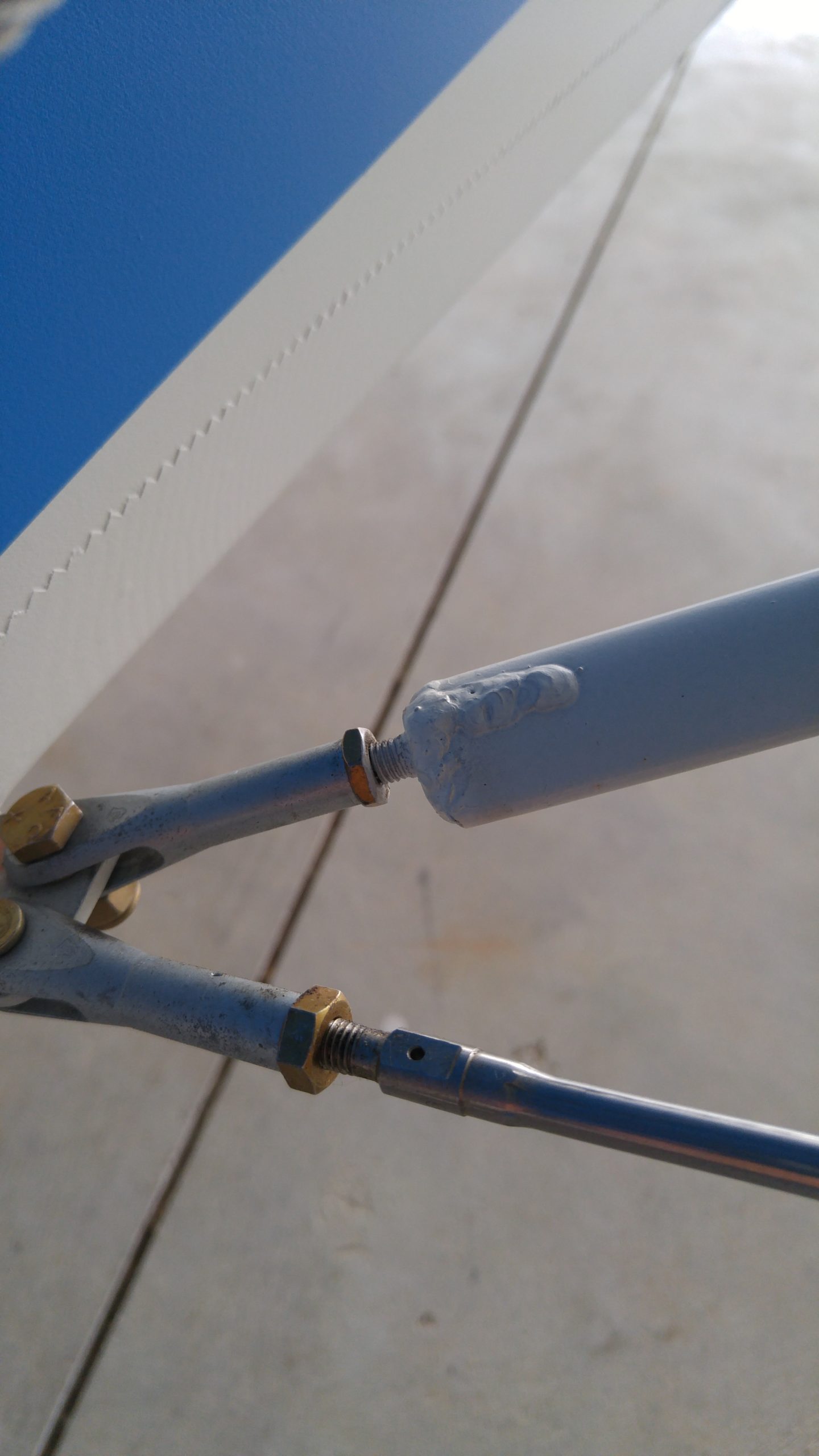
But as things tend to go, fixing one thing seldom means merely fixing one thing. In recent years we noticed that in cruise flight, the elevator was displaced in a stick-forward position from neutral, based on looking out the window at the counterbalance. This meant we needed less incidence already, even without switching to the profiled rib shapes. If we were going to be making new tail struts, we might as well account for this. I mentioned the part failure to Bob on the phone, and he had some input. First, he reminded me that the tail strut we were using didn’t match his original design. The original does not allow for any adjustment, it’s just made in place to fit. In the early days of the factory, the tail struts were made with welded-in AN490s, which paired with the AN665 female-threaded clevis. The thread size is 1/4×28. One of the problems with this arrangement is that in the welding process, the protective cad plating layer is burned off of the AN490. Threads are extreme stress risers, and this combined with inadequate corrosion protection is not a recipe for success.
Bob had several ideas for an improvement, and here are the two that I liked the best. First, he suggested welding a tube onto the end of the strut, cutting female threads into that tube, and swapping the AN665 out for a clevis with male threads. He also suggested considering a 5/16” thread size, which would be much more durable. With this arrangement, the exposed threads would still have their protective plating, and the cross section area of the clevis inside the threaded area would be much larger.
The first step was to have the parts manager get to work sourcing the supplies, starting with a male threaded clevis with 5/16×24 threads. I couldn’t find one in the aviation catalog, but McMaster Carr carries one as part number 4749T11, $6.05 each. Next we needed a foot of 4130 tubing, 7/16x.095. A few inches would have been fine too, but there wasn’t any in the scrap pile and the minimum order is a foot. The tap and drill were already on hand.
Before starting, I measured the original strut length (36-5/8) to make it easier to guess the new length. Next I cut out the old AN490 with my new portable bandsaw mounted in its Swag Offroad benchtop table (thanks for the tip, Rob Caldwell), and was surprised to find water running out of the tube. The bottom end of the strut is sealed, but apparently it was possible for water to run down the leading edge of the horizontal stabilizer, then between the stabilizer and the strut, then between the layers of the smashed strut end. This would motivate me to weld closed, then re-drill the strut top hole, sealing the struts against future leaking.


Once the slots were cut, I drilled just outboard of the end of the AN490, which liberated the old fitting.

A rotary file made easy work of smoothing the remains. The 7/16 tube fit nicely in that slot, needing only prep for welding, and trimming to length once the welding was done.

Cutting the threads into the tube was a slow process of back and forth every quarter turn. If I had any doubts about how much work the tap was doing, the hot temperature of the tube reminded me.

Next, I needed to reduce the incidence angle by shortening the spacers in the horizontal stabilizer mounting structure. Rather than shorten the old spacers, I made new ones at half length. A folded wire tie held them nicely for painting. In the final installation, I installed a jam nut to keep tension on the threads of the clevis, and I ended up shortening the 7/16 tube by about an inch compared to the image above. In retrospect I should have shortened it before cutting the threads, since that would have saved half an hour of tapping. The end result seems very durable, and initial flight tests after the adjustment suggest that if anything, it may not be enough correction, but at least it is a step in the right direction. I’ll need to fly with a heavier load and further aft CG to see where the elevator falls, but it is currently in trail with the stabilizer at casual local flying weights.
A little more room here would have been helpful. Original spacers are 1/2″

Original spacer

New Spacers Cut

Wire tie holds the new spacers for paint

Bearhawk 4-Place Trim Tab Experiment, Lengthening the Horn
Source: 2019 Q1 Beartracks, Tim Babcock
Editors note: Readers may remember Tim’s Bearhawk, modified with control yokes instead of sticks. Even though parts of his pitch system are different, there is useful information here about the geometry of the elevator on the Bearhawk 4-Place. Take note of the recent safety update related to elevator trim cable tension, Bob wonders if this could have been a factor in Tim’s case also.
I was trying to come up with a simple fix for the pitch sensitivity on my Bearhawk 4-Place. Up elevator isn’t bad but down throws you up into your seat belt in turbulent air. Once it is trimmed up and appears to be flying along nice and level and you give the stick a little nudge and let it go it will diverge into these big oscillations and you have to take it back. It will not revert back to trimmed flight on its own. I wanted to keep the servo trim tabs because they are nice for long flights and flying heavy. Nice and light on the controls.
First I started using an electronic level to measure elevator travel and trim tab deflection a degree at a time. But soon discovered that it wouldn’t work because the tab is moving along with the elevator. And in the case of the elevator moving up from neutral, the tab trims down normally for only 7 degrees and then the tab stops trimming down and and just rises with the elevator and the tab degrees rise up instead of down. So the protractor was better.
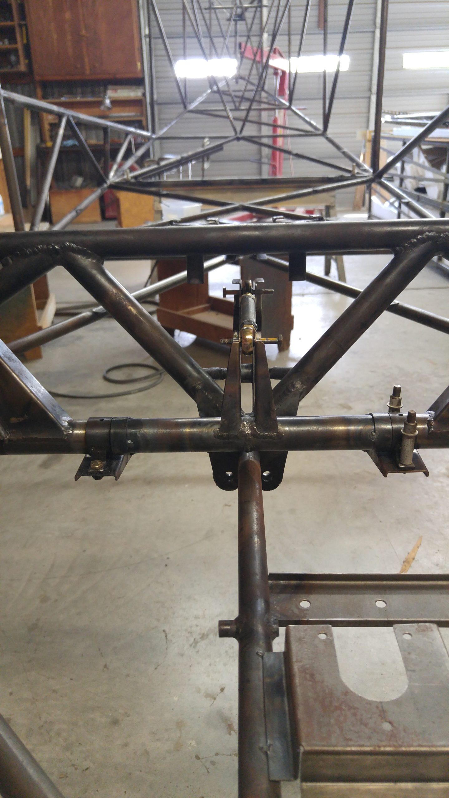
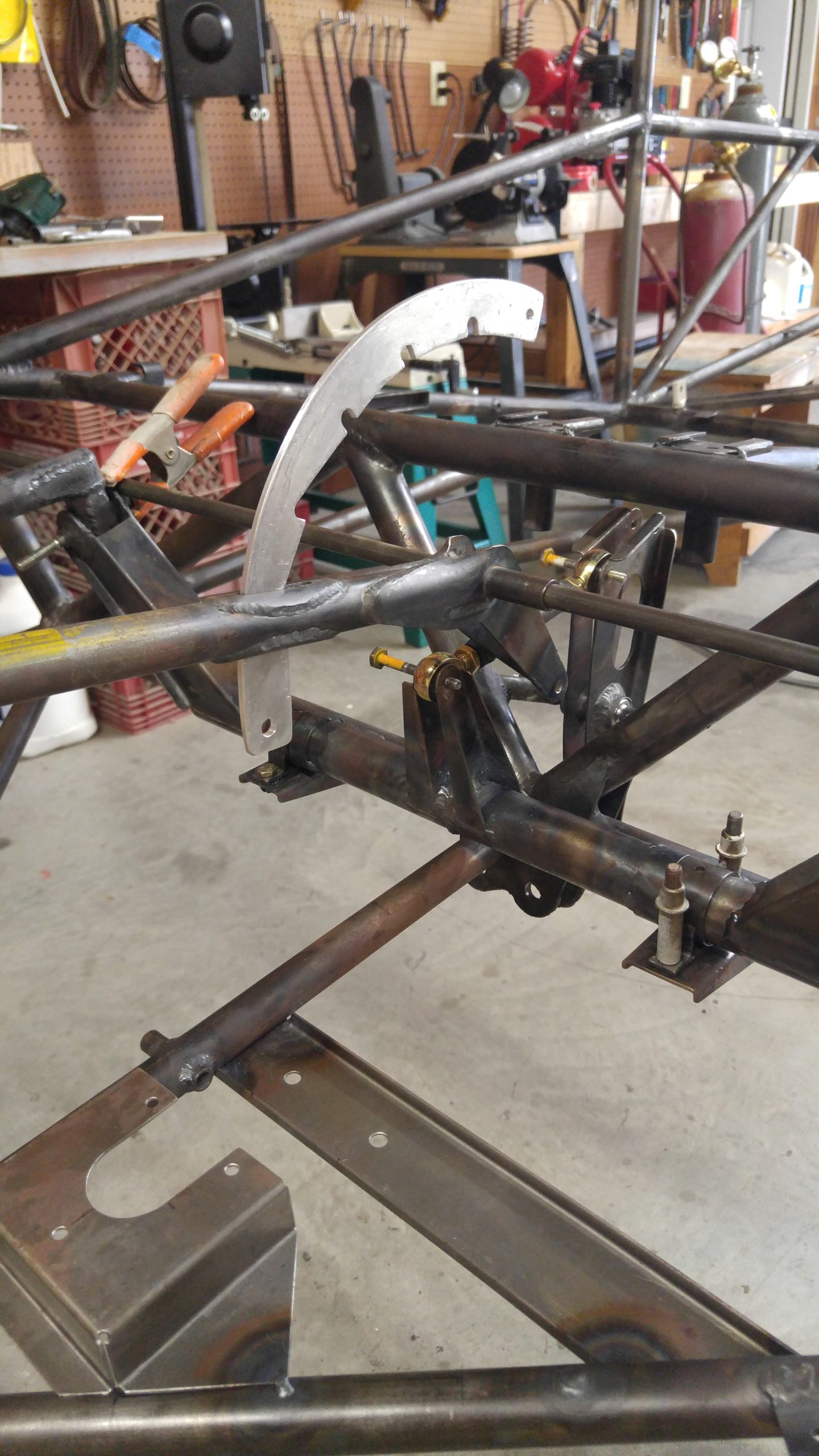
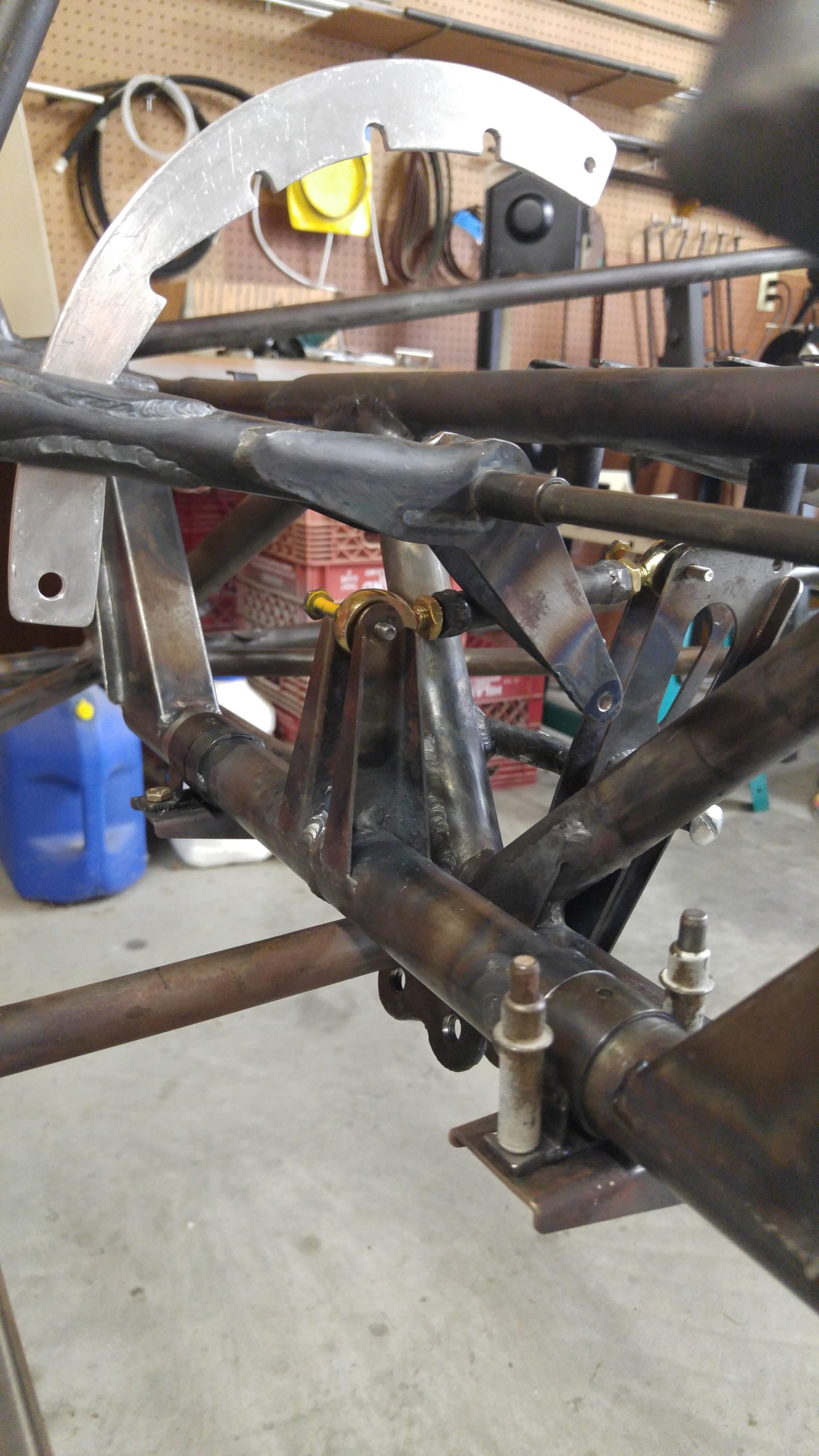
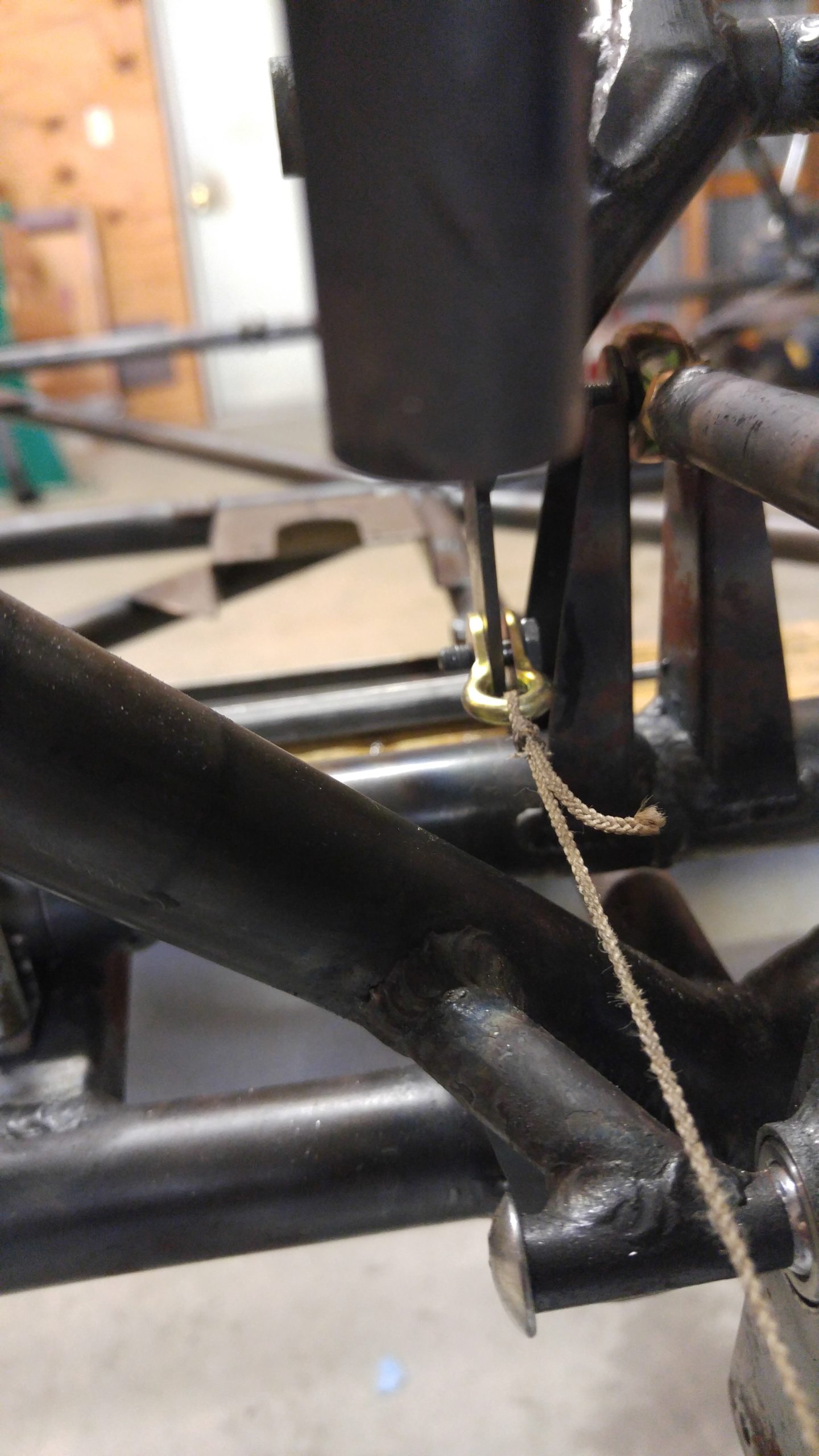
I devised an extension arm that bolts through the original tab lever holes. With the tab lever sandwiched between the longer lever and a dummy lever on one side. The tops of the longer lever and the dummy lever are bent over 90 degrees about 3/8″ wide so when clamped in place the bent over ends can press up on the bottom of the trim tab front tubing for support, to prevent side wobble and then break off the tab. The tab lever was at first 1.8″ longer, from the tube centerline to second hole from the bottom.
The following are measurements of the elevator trim tab and elevator degrees of travel using a protractor, for both the standard trim tab and a modified lengthened lever.
Standard trim tab lever:
Down elevator – 21.3 degrees
Elevator trim tab deflection – 31 degrees up (Compounding Servo)
Up elevator – 29.0 degrees
Elevator trim tab – 12 degrees down
Modified trim tab lever:
Down elevator 21.3 degrees
Elevator trim tab deflection – 15 degrees up (almost balanced with up servo)
Up elevator – 29.0 degrees
Elevator trim tab deflection – 10 degrees down
In normal level flight the tabs barely deflect with average corrections. Before, the down elevator was being trimmed by the tab, which was moving 10 degrees more than the amount the elevator was being deflected.
I have sold my Bear-hawk now due to some health issues. The new owner has moved the trim linkage to the long-est hole now further reducing the up travel of the trim tab, and has no more sensitive trim. Acts in a true fashion and good feedback to the control yokes. Very stable in flight now. The flight instructor who I checked out and who spent 10 hours checking out the new owner said it’s a dreamboat to fly.


Bearhawk Rigging Part 2: Flight Testing and Understanding the Data
Source: 2018 Q4 Beartracks, Kevin Deutscher
Often we experience a flying sensation and report it as “My right wing is heavy” which is a fine statement of what you are perceiving. Observations from a flight experience have a bit of freshness and uneasiness often clouding the senses and information is stored in emotional memory. The take away is, the right wing is heavy. Are you sure? Why is the left wing not light? How do I fix that? How do I validate my feelings? How do you go about debugging an aircraft to understand what adjustments might need to be made to enhance the handling to what you would like it to be? That requirement is going to be different for each of you but similar by mission and convention. We all want a plane that is predictable and capable of flying stable in a hands off environment without quirks.
There is plenty of detailed technical commentary in various EAA, FAA, NASA, Sport Aviation, Navy and Air Force manuals that are excellent reads on the subject of Flight Stability, Handling, Stick Force Gradients, and Positive or Neutral Stability. The vast majority of that has been synthesized into the Bearhawk design and everyday conventional flight expectations. Suffice to say that for a Bearhawk and the “Normal” mission, positive stability is a plane that can remain hands off without deviating from the established trajectory and will tend to return to that condition when disturbed from that condition. Non-conventional flight responses are the primary reason autopilots have difficulty controlling some planes. All the control algorithms are predicated on conventional predictable response to a control output. Autopilot wants a left turn to track the VOR, left turn commanded, left aileron raised but nose yaws right and drops, this makes an autopilot sick. Non-conventional response to a standard input.
That said how do we identify, isolate, and correct an undesirable situation? The answer is, Flight Test. This is something that can be handled in the initial Phase 1 testing and or later as the plane ages and changes from wear or maintenance. Flight testing should be accomplished with a specific purpose and format to Investigate, identify, gather data and observations in a consistent and repeatable manner. When flight testing it will be best to have an observer to assist in gathering and recording data and keeping a visual scan for traffic allowing the flying pilot to fly. Should an observer pilot not be available a GoPro camera and a data download from an EFIS can assist. Always select a clear calm day, at generous altitude of 4000 ft AGL or so away from populated areas.
The aircraft has 3 discrete motions. Pitch, yaw, and roll. Which in a perfect world would not interact, but in reality often do and the test flight effort is to try and sort out the interactions into specific behavior that can be studied and corrected on the ground. When observing a behavior we are looking for direction, rate, force and coupling of off axis effects. OBSERVATION is key. That is all about BIG PICTURE observations, out the front windscreen and the force in your hand.
A technique I like to use is called STOP and it is a great way to move forward.
Stop, Think, Organize, Proceed, each step of the way, planning the flight, gathering the data, understanding the data, adjusting the aircraft. Stop, Think, Organize, Proceed.
It is beneficial to put some structure and organization into gathering the data and prepare some type of log to be the reviewable record. A log with 3 columns, pitch, roll, yaw. The rows are the test being performed. All that is needed is a dot in the column to reflect the direction trend. Dot in the center of the column is neutral. Off center is direction and further off is magnitude. Whatever method works for you is good, keep it simple and quick.
Let’s plan a flight, observe, gather some data, assess the data, compare to our previous geometry measurements and make a change and flight test the change.
Preference is to address the pitch performance first as pitch difficulties cloud other axis issues, interact most with the overall stability and interfere with your ability to debug the other axis if always chasing pitch and hence attitude and speed.
Reported issue: Elevator / pitch is twitchy and requires frequent trim changes:
Load the aircraft to approximately mid CG, two people, full mains, this should be the initial configuration for all testing, no loose gear floating around the aircraft. Head on out to the flight test area and establish a cruise at approximately 90 mph. Maybe 2200 rpm and 22 inches, Trim for hands free. Notice how much stick play there is before a stick input causes an aircraft motion. What is the nose doing in yaw? Is the ball centered? Is the ground track straight with the CL of the aircraft? Can you release rudder pressure without the nose yawing? How much pressure and deflection does it take to keep the nose stationary in yaw? Ailerons, same questions, get this feel into muscle memory. Are you holding altitude? Wait I thought we were working on Pitch? Yes. So now will perform pitch tests. Make the changes slowly, 5 seconds to change, 15 seconds to stabilize. Call out your observations to your data recorder for logging, both visual cues and pressures.
From trimmed stable flight with absolute minimum control input:
Increase power to normal climb. What happens? Reduce power to normal cruise. What happens? Reduce power to approximately 40%. What happens? Back to normal cruise. What happens? Repeat this sequence 5 or 6 times. You will find your observations will be broadened. The first few times you will go tunnel vision, force your focus to be very broad. What is happening is viewed out on the horizon not, on the instrument panel. Try the last one stick free, hands off. Are the results different? In what manner?
Normal cruise power, trimmed hands off pitch. Slowly apply back pressure until the nose is approximately 10 degrees up and speed falls by 15 mph. Relax back pressure. What happens? Reset and repeat 5 or 6 times. Same initial setup, this time forward pressure, relax forward pressure? What happens? Reset and repeat 5 or 6 times. Try the last one stick free, hands off. Are the results different? In what manner?
Head back to the field, let your head chill and let’s review some data.
After compiling the data look to see what patterns are discernable and if they make sense to previous measurements and support the “twitchy” concern.
Looking over the pattern of the data and examination of anticipated or desirable handling some oddities are noticed. What do they mean and how do we make sense of the issue? STOP.
Summarizing the observations from our hypothetical flight data a statement like this can be made:
When adding power the plane accelerates, remains mostly level while banking and yawing to the right. When pushing over from trimmed level flight or power reduction, the nose drops and the speed continues to accelerate, plane does not attempt to return to level flight. Banks and yaws right. Why?
Looking at some of the geometry measurements of our hypothetical aircraft there are some things that might have a bearing or explain what is going on. Horizontal tail is -3 degrees from the level datum and the right horizontal tail is about ½ inch lower at the lift strut attach strut than the left side. The right aileron measures trailing edge low by about ¼ inch compared to the wing tip and the straight line of the wing bottom. The left aileron seems correct.
Conventional wisdom, standard practice and physics dictate with application of power a correctly rigged plane should climb, yaw left, followed by a left bank which slowly transitions to a left turn. When displaced from level by pushing the nose over then releasing forward pressure the nose should rise and return to level flight at trim speed. Our theoretical plane does not perform conventionally.
Keeping in mind right now we are investigating Pitch. It appears the horizontal tail needs to have the leading edge lowered by at least -1 degree to -4 as a starting point. Lowering the leading edge will provide the tail with more down force at a given speed. Increasing the speed will cause the downward force on the tail to increase, raising the nose to get back to trim speed. More airflow, power increase over the tail causes more downward force and raises the nose causing a climb attitude. It seems like there are several data points and measurements to justify a change to the incidence of the horizontal tail surface. When the tail incidence is moved -1 deg, make sure the twist from side to side is eliminated. Making a change has a snow ball effect, now you need to install shims to lower the leading edge. Obtain longer bolts, adjust the horizontal cross tube fuselage covers, and adjust the horizontal leading edge support struts and possibly the flying wires, all the while making sure the changes do not cause binding of the elevator. There is a lot of detail work here and it needs to be done carefully and precisely. These adjustments cannot be just wished into place.
Somebody out there is thinking, that’s a lot of work and my pitch is not totally “Positive” but I can live with it. My real beef is running out of elevator in the landing flare… Well, the solution for more elevator in the flare, is exactly the same. However adjust too far and there are consequences. Like in a high powered go around configuration the nose will go up fast. Be careful. Small changes, one at a time.
So time for another test flight to evaluate the change. If pitch is noticeably improved you can perform the roll / heavy wing data gathering on the same flight.
Investigating the roll tendencies has a different set of variables. Having pitch sorted out makes the workload easier and the plane more stable. Testing the wing heavy or light syndrome will involve separating contributions of flap positioning, aileron rigging, and positioning all the while making sure that the airplane is not skidding or slipping, the ball must be kept centered. That is the job of your feet! Make the pedal pressures as light as possible, do what is needed to keep the plane from yawing. Ailerons inputs should be handled with fingertips on the stick as much as possible.
Reported issue: The left wing is heavy:
The preamble and setup for this testing is the same as the for the pitch investigation. Approach the testing in the following manner.
From trimmed stable flight with absolute minimum control input:
Normal climb power. (Rudder) What happens? Reduce power normal cruse (Rudder) What happens? Reduce power to approximately 40% (Rudder) What happens? Normal cruise (Rudder) What happens? Repeat this sequence 5 or 6 times. Did the wing heavy change as the result of power change?
Flaps up, establish a high power cruise, 120 mph straight and level, release stick, note bank and stop yaw. Reduce power to just above Idle. Slowly decelerate holding altitude, rudder adjust, no yaw.
Let the speed decay to about 70 mph, power up resume cruise. Were there substantial changes to the wing heavy condition? Did the roll tendency increase with speed? Were the stick pressures symmetric or was one direction heavy and the other light? Did the pressures change with speed? When allowing the stick to be free did the stick offset and then the bank stop? Repeat this test 5 or 6 times to be comfortable that you can predict the behavior. Look at the relationships of the aileron leading edges, do they protrude below the wing? How are the relationships of the tips to ailerons? Are ailerons and flaps aligned with each other? Constantly check heading and that the ball is centered.
Repeat the above test with 2 notches of flaps and an initial speed of about 100 mph and decay to just above the stall, recover to level flight. There is no need to enter a stall. Is the behavior identical or different? If different is it better or worse?
Head back to the field, let your head chill and let’s review some data.
After compiling the data will look to see what patterns are discernable and if they make sense to previous measurements and support the “left wing is heavy” concern.
Looking over the pattern of the data and examination of anticipated or desirable handling some oddities are noticed. What do they mean and how do we make sense of the issue? STOP.
Summarizing the observations from our hypothetical flight data a statement like this can be made:
The left wing is “heavy” only when the flaps are retracted and left rudder is constantly need to keep the nose on heading and the ball centered.
Well there are several different ways to approach this paradox. First is the flap configuration change eliminated the heavy wing with application of flaps. When the flaps are deployed they free float and balance air loads equally between the flaps via the “Y“ cable arrangement. Since the wing heavy is reduced with flaps deployed the issue is most likely flap related while in the full up position. The observation that it requires left rudder to center the ball and stop the yaw is of interesting note.
Left wing heavy and left rudder should be causing a left turn but it does not…
There is an ah-ha moment coming here. Lift produces drag. The right wing is producing more lift, raising the right wing, hence the right wing is LIGHTER than left and producing more drag. The induced drag from lift production causes the right wing to have more drag than the left therefore the drag retards the right wing causing yaw right. LEFT rudder is required to eliminate the yaw. With this condition present it is not possible to be sure the ailerons are perfect yet. One step at a time. If you reduce the right lift by raising the right flap a bit then lift will be reduced and drag will be reduced. How much to raise the right flap? Start with 2 turns inward of the threaded rod end at the flap. Yes, time for a flight test. Repeat the flight test data set and make your observations. It should be better. Now pay close attention to the resting positions of all the trailing edges and the leading edges of the ailerons relative to the bottom of the wing. If a wing is still heavy it may be time to correlate the data to the condition and adjust the ailerons. The nitty gritty of the aileron adjustment pressures, feels and differential aileron rigging will be covered in the next installment.
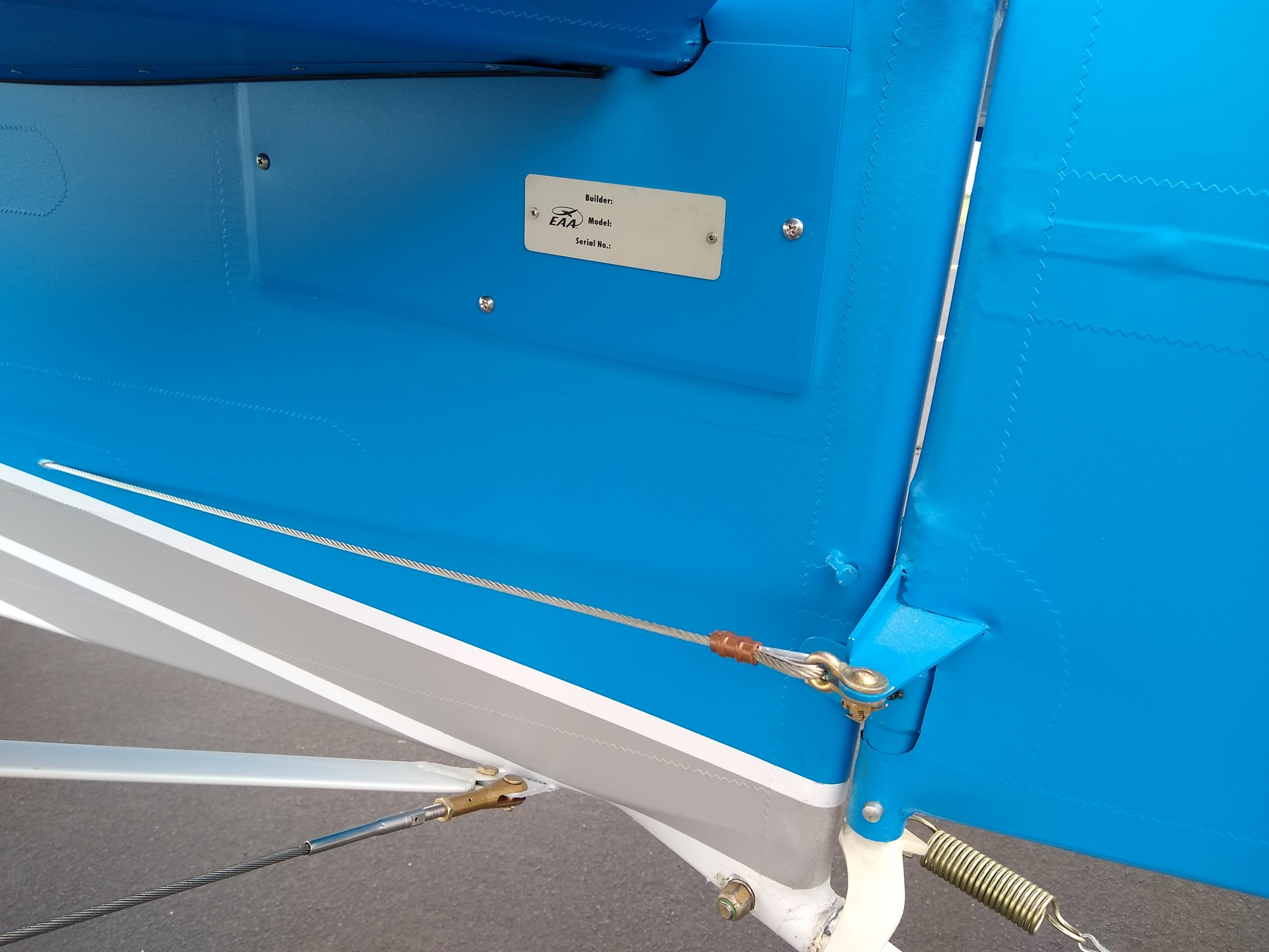
The yaw function of flight coordination is typically a result of pilot responsibilities being left unattended, had to get that in there. After this rigging effort the pitch and roll are better, maybe not perfect, another round of tweaking will be required but you have a system down and the tools to work with the data. There you are humming along and removing feet from the rudder pedals creates yaw and provides your feet constant entertainment. Yes! Yet another flight test is in order but first we need to make a ground installed reference system. With pilot seated in the airplane look down into the foot wells or by the seat edge and find a location where the rudder cable is visible. Establish neutral position of the rudder to the vertical fin and place a tape mark on the rudder cable and the fuselage interior to indicate neutral rudder. Are your feet in neutral on the pedals when the rudder is centered? If not fix that first on the ground.
OK, up to the sky again. Establish a normal cruise power setting and verify straight level and nearly hands off on the stick. Smile! Notice rudder position indicator with respect to centered ball. Remove feet from pedal and note the nose yaw, if any. Where does the rudder position indicator come to rest? Note the displacement of the indicator marks. Head back home.
Looking over the pattern of the data and examination of anticipated or desirable handling some oddities are noticed. What do they mean and how do we make sense of the issue? STOP.
Summarizing the observations from our hypothetical flight data a statement like this can be made:
When in flight and feet off the rudder pedals the nose yaws slightly left and stops with about 5 degrees of deflection. The mark on the rudder position indicator is off by about 3/8 of an inch, rudder deflected left.
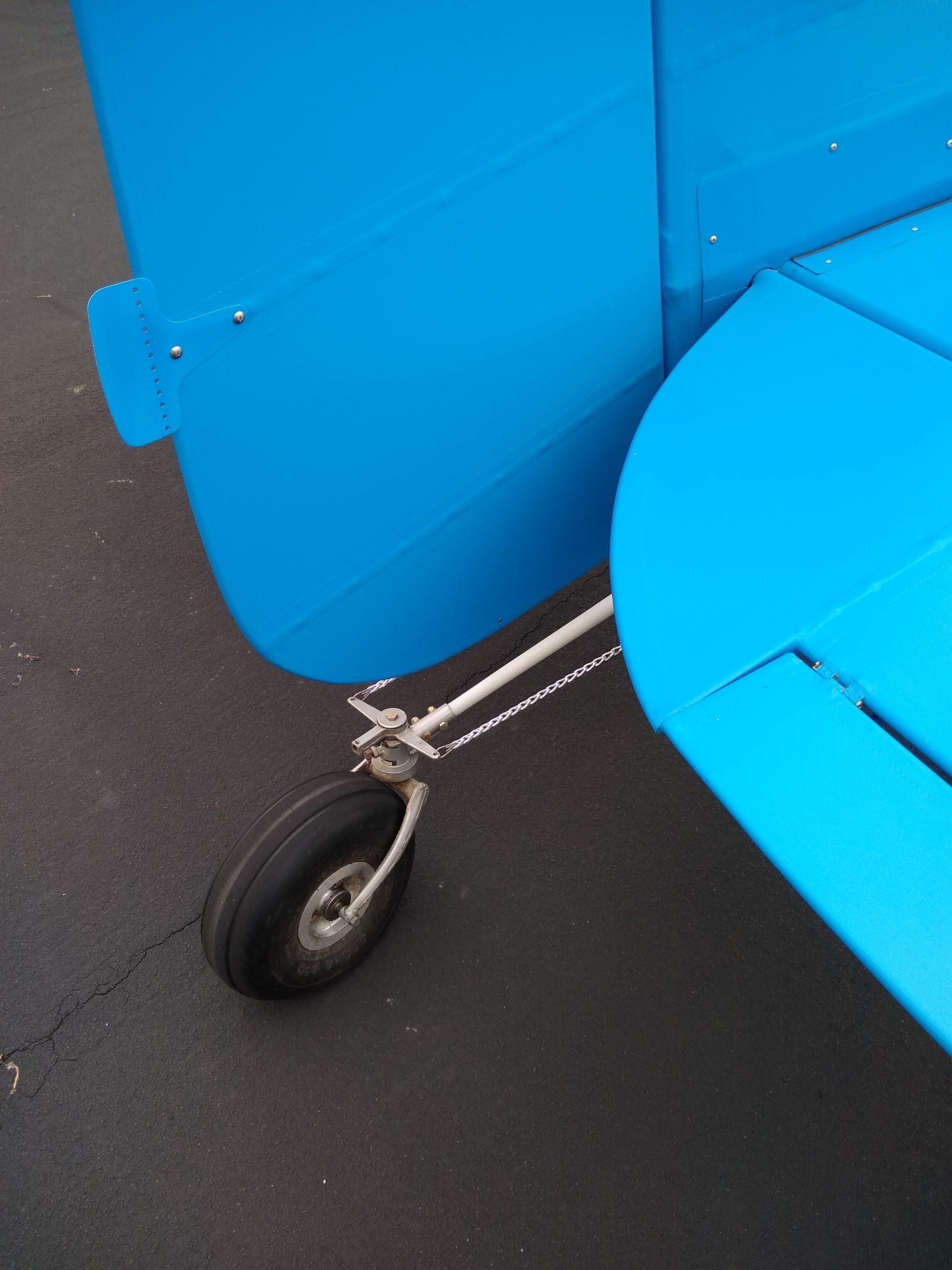
Several possibilities here, add a rudder trim tab, rudder trim system, add more drag to the right wing tip, remove the rudder return springs and insure that they are not causing a rudder bias or add spring bias. Lubricate the rudder assembly. Check the tail wheel springs and the centering of the tail wheel and centering friction because if the tail wheel is cocked and not in trail or the springs are not equal force (Maule Setup) or unequal chains, then tail wheel will be a mini rudder deflecting the rudder causing the yaw!
Hopefully this has helped define a method to assist in debugging and rigging of your plane. This is an incremental process that is iterative and small adjustments have big change effects. It is important not to jump to conclusions and misdiagnose or apply the wrong correction as you may end up chasing your tail and adjusting something to mask an incorrect adjustment. I have walked thru this activity on several Bearhawks and always end up with a hands off stable aircraft with minimal adverse yaw that can be flown and turned rudder only, stick free or aileron turns feet on the floor.
Next installment will address your questions and cable rigging, control counterbalance and differential aileron configuration.
Fly safe with a smile!
Kevin Deutscher, Bearhawk272@Gmail.com