Installing a Lycoming type Engine

Some builders have found it challenging to get the engine onto the mount for the first time. The good news is that these steps are pretty universal, so rather than re-invent the wheel, we’ll provide a few resources that you may want to consider.

Here’s a link to a great article on Doug’s site, targeted to RV builders but applicable for us too.

Similarly, Doug hosts this very good discussion thread with some common questions.

Helpful books, available at the EAA Bookstore:
Firewall Forward: Engine Installation Methods by Tony Bingelis
Tony Bingelis on Engines by Tony Bingelis
Sky Ranch Engine Manual, by John Schwaner

Daryl Rhodes Flies his New Bearhawk LSA N367G

Source: 2019 Q4 Beartracks
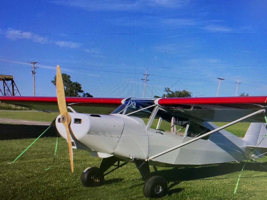
Building a homebuilt airplane is always a large achievement. Daryl built his new LSA in 2.5 years, without a kit! Well, it really took two years of construction, but it took a little while to get all of the paperwork and such done. He used the Stewart covering process, and a “little bit modified” Continental C-90. Empty weight came to Continue reading

Australian Bearhawk Patrol Glider Tug Called “Lucy”

Source: 2019 Q3 Beartracks, Alan Arthur
The gliding fraternity have been talking about auto engine powered tugs for decades and despite the efforts of many they haven’t become a reality (yet), recent changes to Civil Aviation Safety Authority (CASA) regulations have made it a far more practical proposition.
A casual conversation around the bar lead to a syndicate being formed to look at a private venture to install a Mazda 13B Rotary engine in a PA 25–150 (small Pawnee). The syndicate members Alan Arthur, Doug Harrington and Avon Furphy conducted an extensive search for a suitable aircraft and finally dismissed the idea as too expensive, too much work, too many ADs and too many owners that had an inflated idea of the true value of their aircraft.
The idea changed to building a kit aircraft similar to a Piper Super Cub, also with a Mazda Rotary engine. The Bob Barrows designed Bearhawk Patrol was selected and after some consideration an order was placed for a Bearhawk Patrol quick build kit with Bearhawk Aircraft in Austin Texas. The kit was ordered in July 2016 and after a couple of months sorting out options arrived in Perth Western Australia on 29 December 2016.
A couple of days later after it had cleared quarantine/customs, a trailer ride to Narrogin saw it installed in the new hangar at the Narrogin Gliding Club for the build. The kit consisted of a steel tube frame and other welded steel tubes and fittings and lots of raw material. The instruction manual was quite basic but I purchased CDs of the build details compiled by other builders and the kit manufacturer provided hundreds of photographs of other builders projects. The basic airframe went together quite quickly and by the end of January 2017 we had the first visit from the SAAA TC Geoff Danes and the AP for the project Bill Keehner.
Avon already had a Mazda 13B engine sitting in his shed waiting for a racing car project so he donated it to the project, it hadn’t run for many years so was shipped to Rotormotion in Perth for a complete overhaul and conversion for aircraft use. Rotormotion’s brief included a target HP between 210-240 Hp.
The auto engine installation consumed enormous amounts of time as our glider towing goal meant that we could not have any problems with engine cooling at relatively low airspeeds and high power settings. Consequently we selected a twin radiator system and a double sized oil cooler. Experience during the test flying program indicates that we may have got it right.
Avon’s Mazda rotary engine was a fuel injected and electronic ignition version from a Mazda RX7. All of the Mazda fuel injection and ignition system was discarded and instead twin aftermarket EMS Stinger systems were installed driving the standard injectors and twin spark plugs. Also discarded was the heavy exhaust manifold and all the environmental systems. After initial engine runs the custom exhaust was modified to include two straight through mufflers and ceramic coatings on the engine pipes.
PSRU selection proved to be a bit of a problem, all of the toothed belt systems seem to have disappeared, the only system we could find with good reports was a geared system from Autoflite in NZ. This PSRU is available in two or three gear versions and we chose the three geared one to keep the direction of rotation the same as Lycomings. It also moved the engine thrust line up closer to the original design position. After selecting the PSRU then we were able to order a prop to match. We ordered an IVOPROP Corp Magnum three bladed ground adjustable prop of 76” diameter.
The fuel system needed to be modified to incorporate dual high-pressure injection pumps. Initially I was going to build a header tank with dual submerged pumps but in the end found exactly the setup I had planned in an auto supply catalogue at a much cheaper price. The system is now gravity feed to the header tank and high pressure to the injectors, return fuel comes back to the header tank.
The aircraft relies on electrical power for engine operation so it was quite critical that everything was duplicated; not only is everything from dual batteries to the ignition boxes selectable but we have incorporated a panic switch that can change all selections to the opposite selection with the flick of one switch. At higher altitudes you can do some fault diagnosis but when towing a glider at 100 ft you don’t have time to play around with systems.
The airframe is part covered with aluminium alloy and part with fabric; we chose to use the Oratex prepainted fabric. The Oratex fabric is quite easy to use and being prepainted has no hazardous solvents to use, the glue is a water based hot melt glue. The fabric is about 80% the weight of other fabric systems which resulted in the aircraft center of gravity being well forward requiring lead ballast in the tail. If I was to build another Bearhawk I would plan to fit the dual batteries in the rear fuselage and not on the firewall.
Instrumentation did not need to be very complex and other than the engine monitor all are round steam gauges. For the engine management system we used the MGL Extreme EMS display which has the advantage of being in the main programmable. After 19 months, 4450 hours and a lot of engine runs and taxi tests the big day arrived. Word had spread and instead of having a quiet first flight there were dozens of spectators on Saturday 15 September 2018.
The SAAA team arrived early for the final inspection, Geoff Danes and Bill Keehner did their inspections and Bill issued the Phase 1 C of A. The aircraft flies really well; it took to the air as if it was made to fly.


Alan also says: Dennis and Donna suggested that I also send you some photographs of my fool proof control lock (you can’t leave it in and go flying).


Selecting Engine for the Bearhawk Patrol

by Steve Busby, Aerolite Flight Services

The Patrol can accept engines from 115hp to 210hp. The prototype is powered by an O-360 Lycoming 180hp engine, and this is the standard choice among most builders. It is up to the builder to decide on accessories and engine configuration, e.g. carburated vs fuel injected, standard mags vs electronic ignition. The kit is supplied with a Lycoming O-360 Type 1 dynafocal mount. This mount will work on all four cylinder Lycomings except the engines that have conical mounts.

If a builder wants to use a smaller engine, e.g. Lyc O-320, then you will want to keep weight in mind when building. 180hp is very adequate for the patrol, though, as the horsepower rating is stated, you can go higher. As an experiment on an early Patrol kit, we had a 210hp IO-390 in the shop, so we test fitted it to the kit. It bolted right on to the engine mount, but being an angled valve motor, was wider than a 360. To make the cowls look right, it was decided a wider firewall would be needed. We decided right then that the required mods were not worth the extra expense, complications and weight penalty.
The same kit as mentioned above, was fitted with a 195hp IO-375 Lycoming, with dual Pmags for electronic ignition. The accompanied pictures here show that installation, but a 180hp O-360 would be very similar, the large oil cooler being the biggest change. Though the performance with the 375 is amazing, a standard 360 will meet most everyone’s needs and will provide performance beyond most builders expectations.

Comparisons, Compromises, O-540 vs O-360

Source: 2018 Q3 Beartracks, Bob Triplett
Every aircraft is designed with many compromises. One has great speed or short field performance or great slow speed characteristics. I am not aware of any aircraft that has it all. When I find such a plane I will consider building that plane. Perhaps some of you know me or my plane (94RT).

I built 94RT from the kit. It has been displayed in the Bearhawk booth at Oshkosh for a couple of years. Let’s be clear, I do not work with Mark Goldberg and I have no relationship to the company. I enjoy the fellowship with the pilots who are interested in the design, with Bob Barrows, Mark Goldberg and the other regulars at the display. Besides it is a great place to get out of the sun.
This year the plane that Mark uses as a test bed to try new design features and as a demonstrator aircraft to give rides to potential customers due to a glitch was unable to make it to Oshkosh. It got as close as Hartford near Fondulac and was unable to be brought to the show. During the discussions it became apparent that another pilot was going to be required to fly the plane back to the Austin Texas area. In the course of our discussions I indicated that I might be interested in flying the plane back to Texas. After Mark considered my offer for a few days we agreed that I would fly it back.
I have a 180 hp Lycoming O-360A1D engine in my aircraft and have considered replacing that engine with the 250 hp Lycoming O-540 engine. I thought this would be a great time for me to fly behind the O-540 and compare my airplane and performance (O-360) to Marks plane.
I had never flown Mark’s plane so the first thing that I did was do a walk around to see what things I found different in his build than my own and what if any difference that might pose to me on a cross country flight. I had no one around to provide any tips or pointers and I did not want to bend Mark’s plane or add another check marked box on my insurance application.
My first observations were that there were no nav lights, no aux tanks and no landing lights. The plane has the new style B wing and the new style horizontal stab and obviously the 250 Lycoming engine. All of these features would impact my preflight planning.
Next I sat in the plane. I just sat in the plane and surveyed the differences in the layout. What was different from my panel? I closed my eyes and tried to reach for a control with my eyes shut to try to build a mental picture of things in my mind to make the plane more a part of my mental picture and make flying it a little easier. He had some unique differences in his layout. He has the throttle, prop, carb heat and mixture controls on the far left side of the panel near the opening. He likes to work those controls with his left hand and fly with his right. I have a lot of J3 cub time so after 3 landings I had no trouble adapting to this layout.
Another difference is his trim system. I have custom built my own design trim wheel with a 2:1 reduction. My trim wheel needs to travel twice as far as his to get the same effect. I had heard horror stories about the trim wheel being too sensitive and thought I have the tools to build the system and I could do it with a similar weight so I installed my own design. I can report that the factory trim system as provided is not a problem. I had no problems trimming the plane from the first flight to the final flight. I will say that since my system is a 2:1 reduction it requires considerably less force to move mine than the factory system. This difference might be accounted for by either the additional torque of my system or by the setup of the friction in Mark’s system. Knowing what I know now I would not spend the time and effort to install any type of reduction into the system. It is fine just as Bob designed it. Oh, one more thing. I took off with the trim out of adjustment in my own plane one time. Trust me you do not want to do this. The feedback in the stick is really heavy. As part of my preflight I always check the trim tab to see that it is a neutral position.
Another thing that I found different about the plane is that the panel is basic. There is nothing fancy about the panel. This is a matter of taste but if it were mine I would and have installed glass instead of steam gauges. Oh well I started with them and a basic panel, I guess I can survive. It is my opinion that Mark’s objectives are to provide a safe, simple, light design more toward all out performance. Also bear in mind that this aircraft has over a thousand hours flying as a demonstrator aircraft. Perhaps keeping the plane simple is the best choice as people will be getting in and out and cause a lot of wear and tear.
My First Flight
I decided that the first thing to do was to make 3 landings and 3 takeoffs before departing the area. I was not real familiar with the airport but we had just flown in and I had a chance to survey the area and the airport so I thought it best to check myself out in the plane at this airport before flying off somewhere to a strange airport.
As I came in with the power I could noticeably feel the power difference between my plane and this one. I came in very slow with the power and it responded favorably to me. I could feel when it was ready to fly and I was not at wide open throttle so as it began to fly I smoothly came to full power. The climb rate is phenomenal. At 200 feet on climb out I came back to 2400 rpm and reduced the manifold pressure somewhat. I climbed to pattern altitude and turned down wind. At the end of the runway on downwind I reduced power and set the plane up for landing. I had to use caution here because Mark’s plane is in miles per hour and my own is in knots. The first landing was not pretty but it was a nice landing. Remember there are a lot of differences in the two planes that I am balancing.
The second takeoff I now have more confidence in myself and the plane. I came smoothly with the throttle but carefully to wide open throttle. The plane jumped off the ground and we quickly climbed to pattern altitude. I flew a normal down wind and setup for landing as before. This time the plane began instructing me. I got a little low on final. As I added power the nose pitched up. Remember earlier when we discussed the trim and I indicated that the trim has a lot of power. As I fly my own plane I find that it is easier for me to bleed off altitude than to regain it. Also as you bleed off energy on flare it gives me some time to make a smooth flare and touch down. FLY a stable approach as much as you can. The engine has so much power that when you apply power in the landing configuration you will need to account for considerable changes in the stick feedback. After the third landing I felt that while not over confident this was going to be a fun trip and the plane was well within my skill level.
What did I learn here?
The plane is considerably heavier in empty weight than my own. The feedback in the stick is considerably heavier. It is not to the point of being annoying but you do feel the difference. Trim is even more important. Fly a stable approach as much as possible. Make your power adjustments as effective as needed but do it slowly. Be prepared to re-adjust the trim as needed. Remember those controls that are now on the left side. It requires that I take my hand off the throttle and put it on the stick, take my right hand off the stick and re-adjust the trim quickly and reverse the order. Sorry Mark I can live with it but it was not my choice. I understand his motivations. That is the beauty of the experimental plane. I can have it my way. The pane is considerably smoother. The six cylinder engine is noticeably smoother than the 4 cylinder. Mark has the new three blade trail blazer prop on this plane. He says that the prop has 20 percent more thrust. I don’t have a base line to compare the effectiveness of the prop. All I know is that the plane is a HOT ROD. It will well out perform my plane in climb out and speed.
Speaking of Speed
I flew most of the eight plus hour trip at 4500 feet. I set the engine up at 19 to 20 inches at 2400 rpm and saw fuel burns in the 13.9 to 14 gallons per hour with indicated airspeeds of about 135 miles per hour. Mark says that I could have leaned a little more aggressively, maybe able to get it down as low as 12 gallons per hour at this power setting, and perhaps a little less if I reduce the power to that of the 180 hp Lycoming. Yes I know that this does not tell us much as I did not calculate true airspeed. Remember those wings with only the standard tanks in them. I planned 2.5 hour legs which gave me a nice reserve at landing. Here is where I wished for the aux tanks. If you build with the 250 hp engine I would certainly install the aux tanks. At this speed the plane is quieter than my own. His controls are very nicely balanced and the plane is rigged almost perfectly. The engine is so much smoother than mine. It was pleasant to fly. I could trim it easily to level flight and fly it with two fingers. Yes it is tiring to fly in any aircraft for eight plus hours but I did not feel as much strain flying the Bearhawk for eight plus hours as I did riding on and making connections on the commercial plane for the return trip home.
Would I, knowing now what I know, trade my engine for the 250 hp engine? Probably not though I have not ruled it out. If I was flying on floats or spent a lot of time flying in the mountains it would make sense. The exhilaration is a real kick; I am in Wisconsin at 1107 ft. above sea level. My plane performs flawlessly at this altitude. Yes it would do better with the 250 hp engine. BUT remember that fuel flow. I burn 10 to 10.5 gallons per hour. One would also need to spend considerably more to purchase the engine and maintain the engine along with the feeding.
I love that hot rod airplane but airplanes are a compromise and I guess mine is a pretty good compromise after all. What you see here are mostly emotional evaluations and comparisons of my own plane and that of the factory demonstrator. Very little science here, hope you find something of value in this emotional review of a great plane. Thanks Mark for the opportunity to fly your great plane.
Epilogue
Well, it is September 27, 2018 and some time has passed since I flew the 250 Bearhawk and recorded my thoughts. Jared has just emailed me requesting some pictures of the plane to go with the article. I had just hung up the phone after talking with a party that had an O 540-B4B5 235 hp Lycoming for sale at a reasonable price. Yes, once you have flown behind 250 hp. the kick is hard to forget. That take off and climb performance is hard to resist. But I did not bite the bullet. I began to weigh the work ahead if I made such an investment and decided that if I really want that performance I would be just as far ahead to build a new B model plane with that engine in it. My panel is all electric and I just don’t like chopping into the systems to modify it to fit the needs of the 6 cylinder engine, new cowl, new engine mount, new exhaust system and a new induction system all need to be redone. I can do a better job knowing what I did on this plane. I keep telling myself that the plane performs flawlessly in the area where I live. I have two less cylinders to maintain. My engine has all new components in a freshly certified case with just 180 hours. Just look at the maintenance room that I have behind that engine. The fuel burn is less but I have to admit that I do see slower cruise speeds and somewhat less performance than the 250 hp engine. The 180 hp Bearhawk is a fine compromise. Either way you will not be disappointed that you chose to build the Bearhawk. All of the new features and the additional factory work make the plane easier to build and get professional results. Thirty minutes of work on a new plane would equal 2 hours of time that I invested in building this plane.

Bob points out how much room there is between the O-360 and the firewall.

EFII Experience in the Bearhawk Patrol

Source: 2018 Q2 Beartracks, Ed Meyer – Bearhawk Patrol N101EP (Co-owned with Paul Nowaske)
As promised on the Bearhawk Forum after a few requests, here is a write-up of our experience with the Electronic Fuel Injection and Ignition (EFII) system.
Why EFII
As a bit of background, I had a couple years of experience beginning 1969 where I worked in an FAA repair station overhauling Lycoming and Continental engines. My job was to overhaul accessories which included carburetors and magnetos. During this time I gained good understanding how they work and always thought that a carburetor in particular was a pretty crude way to get fuel into an engine. The one plus is that it is very simple. Later, in the ‘80s, automobiles transitioned almost exclusively to using electronic fuel injection and ignition and I observed that the reliability of our cars went up significantly without the frequent attention that the temperamental old systems required. We wanted something more modern for a new airplane.
The EFII system seemed to fill the bill. We opted for the dual system with many redundant components for reliability. We have two of most of the components in the system so that no single component failure will stop the engine. There are two crank position sensors, two MAP sensors, etc. driving two different ECUs. The ignition is driven by both systems much like dual mags where one set of plugs is fired by each. The injection is controlled by one system with a switch to change to the other if needed. This is always checked during run-up assure both are working properly.
Other considerations
The EFII system is 100% dependent on a steady supply of electricity for operation. Therefore we chose to install redundant electrical systems. We have the normal belt driven alternator plus a gear driven alternator on the vacuum pump pad. These each have an Earth-x battery. There is a main bus and an E-bus that each feed the redundant components of the EFII system. One of the optional components in the EFII system is a box called a Bus Manager that helps to insure power is always available. Given our dual electrical systems, the Bus Manager might not have been necessary but one feature included in it is automatic fuel pump switching if the main fails. I once had an engine failure in a low wing airplane which requires fuel pumping. After getting on the ground, luckily safely, and thinking about the events, I could not remember if the aux fuel pump had been turned on immediately. It was on after landing but I don’t know when it got turned on. Lots to think about when it got real quiet up front like where to land and such. The automatic switching appealed to me. This is checked at every engine start. When the system is first powered up, there is no fuel pressure so the Bus Manager switches to pump 2 automatically. Once the pressure comes up the selector switch can be set to number 2 then back to number 1, the main pump, it will stay on number one unless fuel pressure drops.
Installation
The EFII system has a good set of instructions for installation and we had little difficulty with following them. It required pulling the intake tubes from the engine and sending them in to have fittings welded on for the electronic injectors. (I understand the new System 32 EFII does not require this.) Also, the flywheel had to be sent to have a permanent magnet installed for the crankshaft position sensors to detect.
The EFII requires a fuel return line to be installed. We puzzled over this quite a bit to try and make this as simple as possible. Installation of a header tank was considered but rejected for a number of reasons. We finally decided to simply add a fuel fitting bung to each tank at about the center of the wing root rib lightening holes for easy access. A friend was a good aluminum TIG welder and did a first rate job on them. We opted for the duplex SPRL V4-4P fuel valve that includes left, right, both, and off settings for both the feed and return. Not knowing how much fuel returns, it seemed good to return it to the tank is comes from. I still do not know how much returns but I have since seen where some airplanes have return lines going to only one tank regardless of which is selected. This would be somewhat simpler than what we did but I would still want to know that the return volume is relatively small before I would opt for this.

We did have an issue installing the fuel valve. We had the lines all nicely run and hooked up and then during pressure testing it seemed the valve was not sealing as it should resulting in phone calls, emails, returning valve, etc. Turns out that we had installed it wrong! Somehow we had assumed the top section of the valve was the feed side and the bottom was the return. Not correct. After re-plumbing it was fine.
Our fuel system uses Bob’s design through the gascolator. Lines come from fore and aft of each tank to tee fittings inside the boot cowl then through the fuel selector valve to the gascolator. The EFII instructions state that a gascolator is “not required nor desired.” We chose to use it anyway for a couple reasons. It gives us a low point to sample the fuel for contaminants and it provides a screen ahead of the inline fuel filters that are supplied with the EFII system. One critique of inline fuel filters I have heard is that there is no way to tell if they are becoming plugged up. I think with the gascolator, if there were enough contaminants to be a problem they would show up there first.
After the gascolator, the fuel flows through the first inline filter then to the redundant fuel pumps which are under the floorboard near to the fuel valve. The pumps come mounted parallel in a manifold that has a single inlet and outlet. From there the fuel flows past the firewall to another large fine inline filter before going to the ‘rail’ which is hoses running to each injector in series. The picture below shows the secondary filter and fuel lines in-side fire sleeve running to #3 and #1 cylinders as well as the lower spark plug wires. From there a hose connects to the fuel pressure regulator which is mounted on the firewall. Then it returns to the fuel valve and finally back to the tank.

The ignition portion of the EFII installation is quite simple. The two coil packs need to be mounted and there were magneto cover plates provided that had mounting provisions for the coil packs. Crankshaft position sensors need to be installed near the flywheel on the front of the engine and the plug wires had to be made up to length but all the parts were provided. One of the advantages of the system is that it uses automotive spark plugs which are much less expensive than aviation plugs. Knowing we were going to use this system, we had Bob install cylinders set up for 14mm spark plugs when he built our engine. Even with the unshielded wires and plugs there is very little ignition noise in the radio. If I have the radio squelch open I can detect a small amount of noise that changes with the ignition checks during run-up.
Oxygen Sensor
One component that is separate from the EFII system but recommended is the installation of an O2 sensor and gauge for reading fuel/air mixture. In automobiles running unleaded fuel, the O2 sensor feeds back to the ECU so it can automatically adjust mixture for optimum. The EFII system does not use this feedback in order to maximize reliability since O2 sensors often fail, especially with leaded fuel. The sensor is mounted high in the exhaust only 3 or 4 inches from the cylinder head which is claimed to help it keep from fouling. So far so good on ours and I have heard of them going several hundred hours without problem. The mixture gauge, which gives a real time F/A ratio reading, is real nice to have especially when doing the initial setup of the system. In the picture at the right, the F/A mixture gauge is in the center above the EFII programmer with the mixture knob is to the right of it. The switch on the right is to select which ECU is controlling the injection with the 88 ECU normal. The key switch is left of the programmer.
Operation
The EFII system comes with a ‘programmer’ that provides the interface to adjust settings in the system. We opted to install the programmer in the instrument panel but it is not actually required during system operation. I have never changed any settings in flight and do not intend to. I have looked at some parameters occasionally but it is not easy to see in flight.
Before first engine runs, Robert Paisley, the man behind EFII, sent a set of values to update the default settings that were in the system. Robert spent 30 or 40 minutes on the phone with me describing what all the parameters are for and what settings I should change and what to be very careful of changing.
On first attempts at starting, it was somewhat slow to start. The system ECUs are identified and 71 and 88, which is a reference to the rotational reference of the crankshaft trigger sensors that drive them. It finally started by changing from 88, which is considered to main ECU, to 71 and adjusting the mixture knob richer. I later found that the selector switch was installed upside down, (amateur built you know) so it actually was on 88 when it started.

We ran it several times at various power settings looking at the mixture and adjusting until it was about right. This was done by setting the mixture knob until the mixture reading was about 12 to 1 then reading the percentage of knob adjustment on the programmer followed by changing mixture setting values for the various RPMs by an equivalent percentage and trying again to zero it in. This sounds like a lot of ground run time but it actually was not much.
I toyed with the idea of having someone with more recent experience than me make the first flight and there were volunteers willing. I opted to fly it myself mostly because of the EFII system being quite different and by now I un-derstood it better than anyone in the area. While flying I would carefully monitor mixture, adjust the mixture knob and then change settings back on the ground until it dialed in pretty well.
On early flights, the CHTs were a little high so we had to work on that. I think the biggest part of the fix was in-creasing the air outlet size at the bottom of the cowl and installing a lip. We also adjusted the baffles a little espe-cially right in front of #2 cylinder to allow more air to flow past the area that has very little cooling fins. One other change which seemed to help some was to change the timing a little at high power settings. This is also done from the programmer interface. I did not even open the cowling for this. It has settings that increase the timing up to 30 degrees before TDC above about 1500 RPMs. Additional settings retard it back a few degrees at high MAP. I in-creased these setting for a little more retard at high power. Especially for a new engine I would recommend that more retard is good at high power.
Normal Operations: Start-up begins with turn on of the fuel valve (the pump howls loudly if turned on before the fuel valve) followed by turning on the key (equivalent to master switch) which powers up the system. As previously mentioned fuel pump #2 comes on requiring the pump selector switch to be set to #2 then back to #1 which veri-fies the automatic switching function and verifies both pumps are operational. Once the EFIS boots up, I crack the throttle a bit and activate the starter switch. The starter can draw current from either battery or both and all this functionality came prewired with the Bus Manager. As it stands right now, when the engine is cold, I normally have to run the starter for a few seconds, pause a bit, and then activate the starter again and it fires right up. (I under-stand it is possible to update the firmware in order to be able to open the throttle a time or two the get the equiva-lent of an accelerator pump function providing a bit of prime.) If the engine has been run, even after several hours, it starts right away on the first try hot or cold. There are zero hot start issues.
Run-up includes an ignition check where power to each coil pack is turned off momentarily to ascertain that they are fully functional. There is no ‘mag’ drop when doing this. If anything there is a very slight increase in RPM. I suspect this might have something to do with flame propagation in the cylinders and the 1700 run-up RPMs. Also, momentarily switching from ECU 88 to ECU 71 during run-up verifies that ECU 71 system components all work properly. To shut down after flying: turn off the key. Just like a car. I normally turn off the fuel valve as well but having forgotten that a time or two created no issues other than some fuel migrating from one side to the other via the both setting of the fuel valve.
LOP Operation: With the EFII system it is easy to run well lean of peak. I am able to run it at about 16-17 to 1 and it still runs smooth. I can detect a slight power drop with it this lean but it stays smooth and CHTs drop about 20 degrees. According to Dynon, this is nearly 100 degrees LOP. I have thought about changing the settings for fuel flow to automatically lean like this at the RPMs I use for cruise which are generally anywhere from 2200 to 2400. I have been reluctant to do that because I am afraid that while increasing RPMs like starting takeoff, or going around, it might cause a stumble when going through these cruise RPMs. The benefit of this would be that the mix-ture knob could simply stay centered for all operations. Instead, for now at least, it is set to be equivalent to full rich when the knob is centered and when in cruise I can turn the knob to about the 10 o’clock position for LOP. This works easy and predictable. A good thing is that once set, it stays even when changing altitudes. A before landing checklist item is to reset the mixture knob back to center much like setting the mixture to rich for legacy systems.
Would I Recommend EFII? Yes. The engine runs very strong and smooth. I have no way of knowing how much power it is actually making but it feels strong and others have commented on the performance of the airplane. There is definitely a learning curve with the system. There is little doubt that it was somewhat more expensive than an old fashioned carburetor and magneto setup, especially with the addition of the second alternator and battery. Is it worth it? It was for us. I like it.
Robert Paisley adds: “Since Ed’s EFII installation, there has been a major update in the design of the EFII systems.
EFII is in the process of releasing all-new control electronics with many added features designed specifically for the needs of experimental aircraft. The updated EFII kit is called System32 – additional information can be found at www.flyefii.com.”

Installing the Engine Mount

Engine installation
Like covering, installing the engine is another of those areas where there are so many other information sources available that for us to go into detail would be redundant. We’ll hit each of those areas that are unique to the Bearhawk and give references for the rest of the information.
Engine installations are nothing new, and the Tony Bingelis book “Firewall Forward” is a great reference. Preparing for the engine installation can be intimidating for a first-time builder. Start somewhere, and take it one step at a time. That somewhere might as well be the engine mount.

Installing the Engine Mount
Run a 3/8” reamer through each of the engine mount bushings to bring them up to size and clean any welding scale out. Your engine mount was welded in a rigid jig, but like all engine mounts, the legs may displace slightly during welding, so it is normal to need to spring as least two of the legs into position.
Put the mount up in position and slide a bolt into the top, right leg. Then grind a slightly rounded point into a 3/8” hardware store bolt and slide it into the top, left fuselage bushing from the rear. By springing the motor mount leg, you should be able to push, or gently tap with a small hammer, the pointed bolt in far enough from the back to the hold the leg in position. Then put the permanent bolt in from the front and tap the temporary bolt out. Repeat the process until all the bolts are in position. We recommend a washer under the bolt head, and 1-3 washers under the nut. Nyloc nuts are acceptable if behind the firewall. If you install the bolts with the head in the cabin, use drilled bolts, castle nuts, and cotter pins. Nyloc nuts are not acceptable when they might be exposed to temperatures warm enough to soften the plastic.

Rubber Isolators
O-540’s have two different diameter holes in the mount lugs, which are bolted to the case. If you have a 2″ hole , then you need the Barry PN94011-02 (Lord J9613-12) isolator and the Type II mount from Bearhawk Aircraft. If you have a 1 3/8″ hole on your engine, then you need a Barry 94110-01 (Lord J7402-24) and the Type I engine mount. On the 94011/10-02 isolator, there is a top and bottom (one hard and one soft half per mount). Pay attention to the installation directions that will come with the rubber units. Some isolators are directional, meaning that one pad is much stiffer than the opposite pad. The stiffer pads are meant to go in the back, against the engine mount, to take the weight of the engine when the aircraft is sitting on the ground. The stiffer ones are easy to pick out, they have a “ridge” that is molded into them. If they go in backwards, your engine will sag quickly. Builder Zane provides this image and commentary:

To save anyone else the time calling Lord/Parker, I’ve attached the drawing showing the correct orientation of the two discretely numbered halves of the J-9613-12 mount kit (used with Dynafocal Type 2 and 2” I.D. ears.) The halves get flipped from front to rear on the bottom ears, presumably because they’re of different durometer elastomer and it puts the load on the firmer ones.


O-320/360’s use the Type I mount. Measure the “cups” that are welded to the engine mount. If the cups in the engine mount are around 2-5/8 inches in diameter, you’ll want Lord J-7402-16 or Aircraft Spruce P/N 08-03600 if you can get them.
Larger cups use Barry 94011-20 or Lord J7402-24 isolators.
Builder Ivan H. did some research and found the following about the Lord 7402-24 vs the 7402-16:
I spoke with a Lord engineer again today. The gel filled spacers are designed to prevent metal to metal contact between the spacer and the inner portion of the dynofocal mount ring during start up and shutdown. That is when the engine experiences the most twisting in its mount. He also said that if a person wanted to save a few bucks, the gel filled ones are only needed on the upper left and lower right locations (as viewed from the cockpit in a front engined plane) to get the same protection. So if one is concerned about that sort of thing, get the Lord J-7402-24’s for those locations and the J-7402-16’s for the other two locations. They have the same stiffness He did acknowledge that many installations don’t need that protection, but couldn’t comment on the Patrol due to no engineering data.

Continental 0-470’s use Barry 94110-40 or Lord J6545-1 isolators.

Exhaust Systems

The prototype Bearhawks had hand-fabricated exhaust systems made from thin wall, electrical conduit and have served the designer well for years. However, there are ready sources for custom Bearhawk exhaust systems, for those who want a stainless system and can’t, or don’t want to, fabricate it themselves.
Most builders have a system made by Clint Busenitz at http://www.vettermanexhaust.com/
Alternate suppliers:
Andre at Plane Xhaust in Fort Lauderdale, FL 866-312-4122 http://www.planexhaust.net/

Engine Baffles

Although it is absolutely possible to make your own baffles from scratch, using poster-board templates, many builders shortcut the process by starting out with baffle kits from Vans. Pick a set that matches the engine you are installing, with the RV-10 kit being for the 0-540. For the smaller engines, the two-seat RV kits will work best. Be sure to get the fuel injected version if you have the angle valve engine, or the carbureted version for parallel valve engines.

Keep in mind that the baffles are subjected to an extreme operating environment with lots of vibration. Be especially particular about stress risers and imperfections at the edges and holes.

Once the baffles are installed on the engine, you’ll need to trim (or extend) them to allow for a 1 inch gap between the baffles and cowling. Once the baffles are close enough to shape that you can install the cowl without making contact with the baffles, one trick to model the cowl shape onto the baffles is to mount jumbo paper clips on the baffles every inch or so. Carefully install and remove the cowl, allowing it to transfer its shape by moving the paper clips down.

All openings in the baffling, any areas that would allow air to escape, need to be sealed with High Temp RTV.

A Note on Baffling Theory
The goal of a good baffling system is to move as much air as possible through the cylinder cooling fins as efficiently as possible. This is accomplished by baffling in such a way that there are no leaks and the only way air can leave the plenum on the top side of the engine is by going either through the cylinder fins or the oil cooler. This maximizes cooling and minimizes cooling drag.


View of rear of spinner area: A nose baffle, as shown, stops circulation and leaks around the nose of the case.


When trimming the baffles enough room must be left between
the baffle and the cowling for the baffle seal.


Note the relationship of the rear baffle to the string, which stretches from the nosebowl to the firewall. Van’s baffles are too tall and using strings will establish the proper height.

Oil Coolers – Selection and Mounting

Keeping oil temperatures within limits is an incremental endeavor that is won and lost in small performance improvements that add up in small 5-10 degree leaps. You’ll need to construct a robust system that includes enough of these improvements to keep your engine cool, but you won’t know how much effort to exert until you’ve started flying collected measurements. Some builders bolt on whatever they can find and fly happily into the sunset. Others have to work hard to get every degree that they can.

The whole oil cooler situation can be frustrating. It is clearly a part of the engine system, but if you ask an engine manufacturer what kind of oil cooler to use, they’ll tell you to consult the airframe manufacturer, since it’s not an engine part, but an airframe part. You can ask the folks who sell the oil cooler how much support is required, and they’ll tell you “as much as you can provide.” This is obviously of little help to the homebuilder.

One good strategy is to find someone else’s successful installation and duplicate it. There have been many successful oil cooler installations, and many unsuccessful installations. If you can keep the temperatures where you’d like without any structural cracks in 50 or so hours of flying, then you’ll know you’ve done it right. It is not advisable to duplicate an installation that has not yet proven itself in service. Consider type-certificated airplanes of a similar performance envelope, and if all else fails, see how the RV guys do it. Be aware though that several Bearhawk builders have found the basic configuration drawn by Vans to be inadequate, perhaps due to our lower cruise speeds and generally larger engines. Then again, several RV builders have come to the same conclusions.

First, which oil cooler should you choose? There are two major construction categories, drawn cup (below, left) and bar and plate (below, right).

Aeroclassics sells the latter as a high efficiency version. The ends of the cooler will reveal the type.
Drawn Cup:

Bar and Plate:

Both types of cooler construction are be stacked into layers to determine the cooler size. For engines less than 180hp, smaller 7 and 9 row coolers may be adequate. Larger engines will probably require larger coolers, perhaps 13 rows or more.

High efficiency coolers are also available as single pass or dual pass. The dual pass coolers have two stages, so you can think of them as two small coolers in series.

We recommend new or professionally reconditioned oil coolers, because they are a common trap for engine debris. While you are ordering, get the appropriate steel AN fittings for the size of the lines you’ll be using. Most Lycomings use 5/8” (AN-8) lines, and most coolers are provided with pipe threads. Fittings to consider include AN816 (straight), AN823 (45 degrees), and AN822 (90 degrees). The lines will need to be flexible, and should be fire sleeved and pressure tested before you use them. 500 PSI is plenty. Some builders have found that smaller -6 lines restrict flow, thus slowing the oil enough to allow it to spend slightly more time in the cooler, and thus lower temperatures.

The mounting location will vary depending on the type of oil cooler you choose, and where it will fit. One option is in front of the engine, with the oil flow horizontal and the airflow vertical. For Lycomings, this would be in front of the number 2 cylinder, since it is positioned further aft than the number 1 cylinder. In this location, the cooler will have access to intake air that has not been warmed by the engine. This location will require longer hoses though, since the engine oil outlet and inlet are at the accessory case. Another option is vertical on the aft baffle (air flow horizontal), usually behind the number 4 cylinder. Both of these baffle-mounted locations will require structural enhancements to the baffles, which will need to carry the heavy cooler without generating cracks in the long term. The cooler will be subject to all engine vibrations, which will be substantial.
Mounting the cooler off of the engine will reduce its exposure to vibration, but will require flexible ducting to get the air from the high pressure area above the engine to the cooler. 4” SCAT type ducts are often used, but keep in mind that the rough surface inside the duct can generate pressure-robbing turbulence. Consider also SCEET type of duct, which has a smoother interior. You’ll get the best performance if you can make bends with smooth fiberglass plenums, while using the flexible duct on the straight runs. Plenums are available from Airflow Systems, or you can make them using lost foam male mold techniques (Google it).
When bolting the cooler in place, put tubing spacers that run between the two flanges of the cooler so the mounting bolts engage both flanges and don’t compress them together. The flanges of the cooler are aluminum, and as substantial as they seem, a single flange isn’t intended to support the cooler by itself. They are very soft and bend easily.

If your installation proves successful, please come back and add a comment with the details, or provide some documentation for the Beartracks newsletter, or a post on the message board. Successful data points are welcome.

Photos of a successful installation provided by Mark Goldberg: