Source: 2022 Q1 Beartracks, Bruce Case
Installing the hinges on the ailerons and flaps requires a methodical approach to turn out well. Here is the method that worked out for me. I first made two jigs to aid in drilling the aileron and flap hinges. The first jig shown here allows me to precisely locate both the bolted mounting holes and the hole which the ailerons and flaps pivot about. I used hardened drill bushings in my jig but you could simply do this with a large piece of angle iron. Just be careful that your drill is perfectly perpendicular to the hinges when drilling. What is most important is that you create the hinge pivot hole in all hinges at exactly the same distance from the mounting face of the hinge. The jig will guarantee this. If these holes are not precisely placed the hinge pins will not all be perfectly horizontal and binding of the aileron or flap can result. The locations of all the holes are called out in the plans.


Above is a picture of the jig in action. I use clamps and a vise grip to securely hold the hinges while pilot drilling the mounting holes with a #30 drill. I then pilot drill the hinge pivot holes with a #16 drill and then open up the pivot hole to the final dimension using a .188” ream which is the perfect hole size for a good fit on an AN3 bolt.

The photo above is my second jig in action. This jig precisely locates the location of the rod end bearing hole in both the long arm aileron and flap hinges. These holes are pilot drilled with a #16 drill and then reamed to .188” for an AN3 bolt.

Above is the hinge after drilling the rod end bearing hole. All necessary holes have now been placed in the hinges.
The hinge mounting procedure is the same for both the flaps and ailerons so I will only illustrate the aileron here. Note that the hinges will be offset in their pockets. This allows easy insertion of the hinge bolt. The plans call out an 1-3/8” centerline location for the hinges. Make a .628” wide aluminum spacer. Taping this to one edge of the pocket will give the necessary 1-3/8” centerline dimension when the hinge is butted up against it. Refer to the plans for the correct location of the 1-3/8” dimension as you don’t want to tape the .628” spacer to the wrong edge. You will only use the .628” for the first pocket as the location of the second set of hinges is governed by the 2nd steel pivot bracket attached to the spar:

The aileron is located flush to both the top and bottom sides of the wing using two contoured wood templates. I made this template using the wing Mylar airfoil plot furnished with the plans. Note you will want to create a little additional space at the rear of this wood pattern to allow the aileron some latitude in front to back positioning. It is important to clamp the wood pattern firmly to the wing so there is no gap. You will have to start out with this wood template slightly loose to allow for moving the aileron around to the
correct position:

Select the correct hinge bracket and place it against the spar and the .628” aluminum spacer previously taped down. Insert the longest AN3 bolt that you can install in the hinge. I found that an AN3-11 was perfect.
Now apply pressure so that the hinge is firmly pinched against the .628” aluminum spacer and then move the two wood wing templates into position so that they are tight against the wing and the aileron. This takes some time but can easily be done by one person. The goal is to have the hinge tight against the .628” spacer and tight against the spar. The wood template will force the aileron into the correct location. Now with everything held firmly move the hinge up and down so that the AN3 bolt is perfectly horizontal when sighting from the rear of the aileron. The hinge is now in the correct position for drilling the first hole. I secured it firmly in position using a ¾” piece of wood and a small C-clamp at the bottom of the hinge before drilling (photo below).

Using a right angle attachment drill a #30 hole in the top hole location only (photo below).

Now remove the aileron from the wood wing templates and carefully open up the #30 hole you just drilled to the correct size for a #6 screw. Mount the hinge using a short #6 screw and nut. Remove the C-clamp holding the bottom of the hinge and firmly holding the hinge in location against the .628” spacer drill the bottom hole to a #30. Enlarge the hole just drilled to a #6 screw and attach using a second #6 screw and nut. This first hinge is now securely located.

Make a wood spacer block that is .288” thick. This is the required gap to just clear the hinge bearing. Insert the AN3-11 bolt into the hinge hole as a visual reference. Insert the 2nd half of the hinge bearing into position. Now move this hinge up and down to get the AN3 bolt as horizontal as possible. You can do this visually by sighting along the rear of the aileron. With the 2nd hinge in the correct location use a clamp to firmly hold it in position. You can also add a vise grip as I have shown in the picture to the left for more clamping power. Now pilot drill both holes with a #30 drill. Enlarge all the holes for #6 machine screws and then attach the second hinge half with #6 hardware.


At this point you can use the same procedure to drill and mount the second set of hinges at the other end of the aileron. Again use the two wood wing templates for positioning the aileron vertically. This time you will not use the .628” aluminum spacer but rather you will locate the first half of the hinge visually so it is perfectly vertical and parallel to one side of the aileron pocket and snug up against the 2nd hinge bearing. Again use the two wood wing templates to firmly push the aileron into the correct position. This second operation takes more time than mounting the first hinge in the first pocket as you don’t have the convenience of the .628” spacer. When everything is located draw a reference line using a small Sharpie along one edge of the hinge. Drill the first #30 hole as on the first hinge set with a right angle drill. Remove the aileron from the wing. Mount the hinge using the hole just drilled with #6 hardware and then using the Sharpie reference line, locate and drill the second #30 hole in the hinge. Enlarge that hole and mount the hinge with a second set of #6 hardware. Now using the .288” wood spacer locate the mating hinge and again use the AN3-11 bolt to visually get the correct vertical location of this 2nd hinge half. Drill and mount the 2nd hinge half using the same procedure as outlined in the first pocket. Reinstall the aileron on the wing and check for correct location and freedom of movement. At this point you will remove all the hinges and enlarge the mounting holes to .188” first with a drill and then final reaming to .188”. All the #6 hardware holes in the spars will also get enlarged to .188” in preparation for riveting on nut plates.
Below you can see the finished 2nd set of hinges mounted with AN3 hardware and also showing the required joggle to create clearance for the Aurora rod end bearing.

Updates from Bob, 2021 Q2
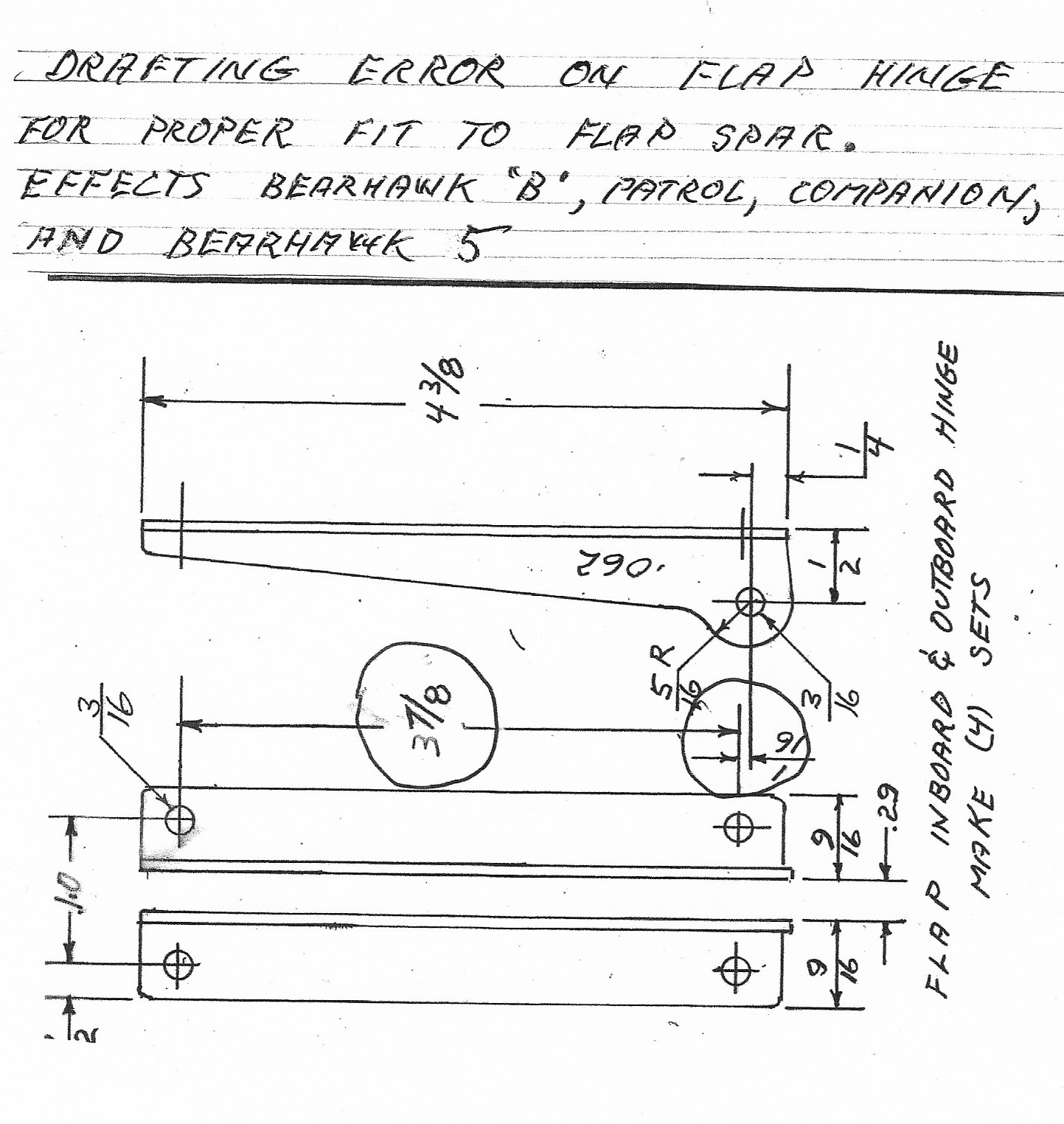
There have been two recent safety updates. The first was a minor drafting error in the flap hinge, which impacted the Model B 4-Place, Patrol, Companion and Five, and was distributed in April. This photo shows the revision:
There is also a new update released 6/28/2021, which will also show up at bearhawksafety.com in the coming days. This is an Engineering Change that relates to the way the covering is tucked into the channel at the top of the windshield.
Bob’s instructions are, “Fabric attachment at top of fuselage to windshield mounting frame channel- A few aircraft have had fabric come loose. As shown is a good way to glue in place.”
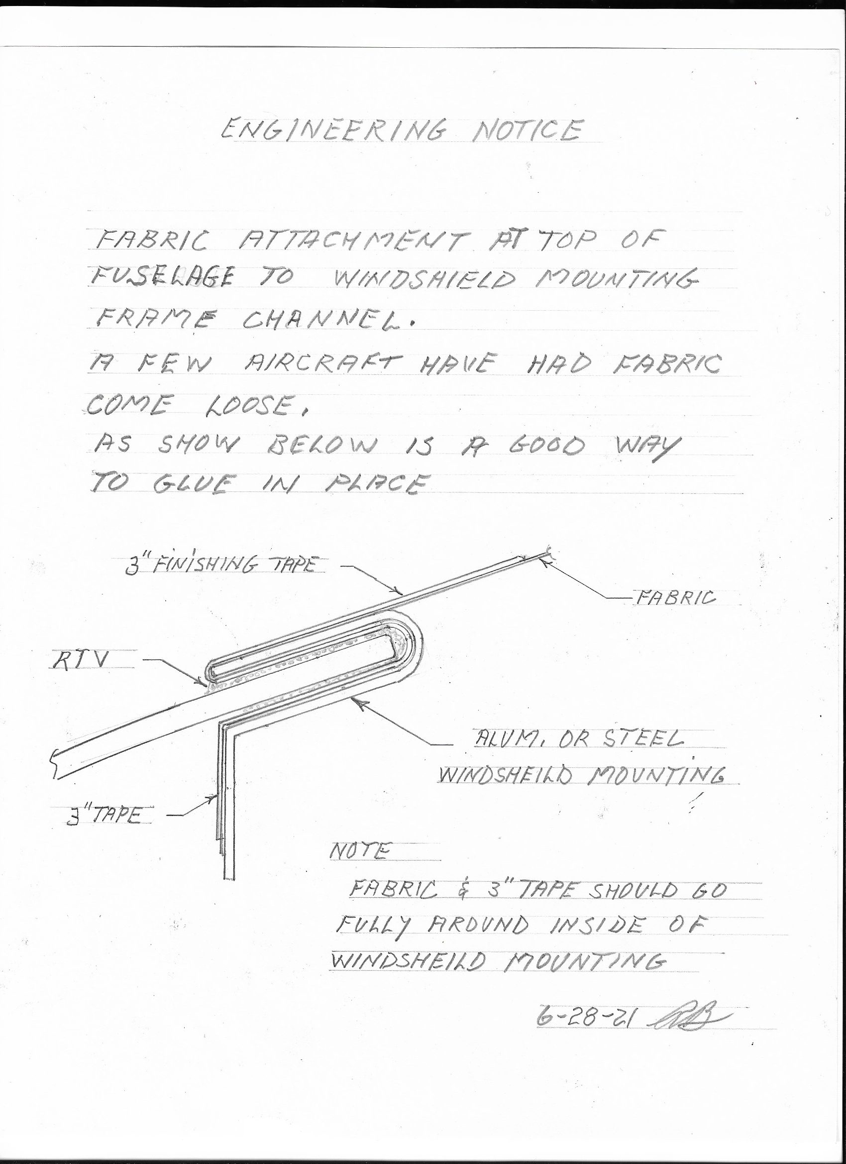
If your fuselage is already covered and isn’t routed as shown in the update, he says, “If it has been flying for a while, it should be fine, but it is something that we need to let people know about.” Bob also brings up the point that it’s crucial to follow the instructions of the covering system that the builder selects. Popular systems including Polyfiber, Stewarts, and Oratex vary greatly with crucial details. In a recent case, reinforcing tapes were able to peel up with fingernail intervention, which prompts Bob to bring up that point.
Bob and Mike have been busy building engines, trying to reduce the lead time which has grown long due to strong demand.
His Bearhawk LSA is back to flying status, thanks to builder Collin Campbell in Missouri. Bob flew the airplane home and was pleased to report it flies straight after the extensive rebuild. Some of the original engine parts fly again in the new plane. Continue reading
Use Loc-Tite for Preliminary Fit of Aileron and Flap Hinge Rod Ends
Source: 1999 Beartracks, Bob Barrows
It is recommended that you Loc-Tite the rod ends into the hinge mounts on the final fit after welding and painting. If all checks out well rivet the rod ends in place with two 5/32″ AD rivets.
Flap Hinge Mounts: Tack Weld At First
Source: 1999 Beartracks, Bob Barrows
Refer to drawing #13. When making the flap hinge mounts it is best to just tack weld the pieces together first and not finish weld until the wing is finished and the flaps are in place. This will allow you to cut the tack welds and realign the hinge mounts if needed in order to achieve the best fit up between the flaps and wing. Once the fits are established then remove the fittings from the wing and finish welding.
Flap hinge mount as removed from welding jig, tack welded together only!
1998 Inboard Flap Lever Engineering Notice (280 and below)
Source: 1998 Beartracks, Bob Barrows
Reference drawings #12 and #14 for plans serial numbers 280 or below.
Inboard Flap Lever
The inboard flap lever arm was shortened from 4-1/8″ to 4″ for clearance with the aileron cable. If you have completed this assembly you may remove up to 1/16″ from the tip of the flap lever arm for clearance. Continue reading
Welding Jig for Flap and Aileron Hinge Mounts
Source: 1995 Beartracks, Bob Barrows
Profiled Aircraft Tubing
Accurate profiled tubes for your aircraft tubing requirements are available to homebuilders from VR3 Engineering. VR3 custom designed and built a cnc tube profiling machine with a milling cutter to produce tubes with unprecedented accuracies and convenience for the homebuilder or a manufacturer. Why cut and fit tubes any other way?
Cutting profiles are generated from computerized 3D solid models to maintain dimensional accuracy, nested intersections and detailed profiles. Both ends of the tube are cut in one setup to ensure this accuracy on the profiles, the clocked orientation, and the tube length.
Homebuilders will appreciate the time savings and convenience of using profiled tubes while maintaining the economy and satisfaction of a plans built airplane project. The quality available surpasses most airplane manufacturers. Home builders will quickly realize the value and convenience of profiled tubes.
• elimination of measuring, manual layout, cutting, grinding and secondary fitting;
• accurate profiled tubes ready for tack and finish welding, no grinding or fitting
• unprecedented intersection accuracies without gaps for an optimum weld joint.
• unrestricted 3D geometry, cluster and nesting configurations
• clean cut edge surfaces, ideal for welding
• no wasted or left over material to store
• all tube sizes from .375” to 1.5” od, any wall thickness per plans.
• eliminate concerns regarding heat affected zones, changes to metallurgy, oxidized cut surface
• simplified welding jig and fixture requirements; profiled tubes are the fixture
• easier and simpler welding techniques.
The rewards homebuilders will recognize beyond the time savings and quality include:
• progress for every hour of build time
• reduced frustration, rework and wasted materials
• enjoy building your project
Profiled tubes are available as kits for fuselages, engine mounts, landing gear and miscellaneous components. VR3 will produce 3D models for plans-built aircraft or custom weldments. You may have had a chance to see VR3 at Oshkosh 2005. In any case, inquiries and questions are welcome. Check the website at www.vr3.ca and click on ‘profiled aircraft tubing’ for additional information and photos.
Contact: Don VanRaay or Menno Peters
VR3 Engineering
65 Cherry St.
Stratford, Ontario, Canada N5A 2E9
Ph # 519-273-6660
Fax # 519-271-6888
Website: www.vr3.ca
Email: dvanraay@vr3.ca