Flight Testing Progress Report N907PM, plus Control Locks for the Flaps and Ailerons, Tail Lift

Source: 2024 Q3 Beartracks, Paul Minelga
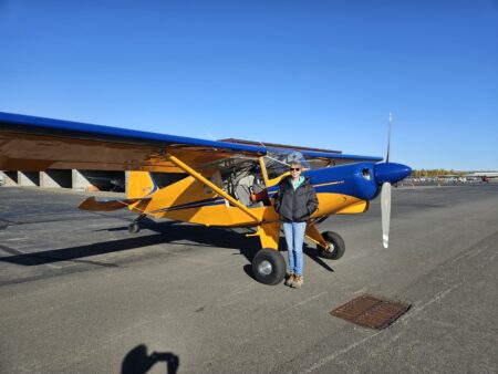
Here’s an update of N907PM’s flights, up to 28.2 hours on the Hobbs. Well, there isn’t much to update! This may be shocking to some, but completely logical to me, so let me walk through the hours from first flight to present.
I already went over my first flight in the previous Beartracks article and YouTube video, so no surprises there. So what happened next? Extensive testing of the flight envelope? Figuring out the handling characteristics of my Bearhawk? Multiple stalls, turns, simulated engine failure, full-flap landings? Nope. None of that…well, almost none, but I will explain why and you can critique as you wish.
The first flight was certainly an exhilarating experience. It was the first date with a new machine, flying at the upper range of its engine and airframe performance envelope. The excitement of not knowing which sounds were normal and which sounds could be the beginnings of a catastrophic event was to be experienced, as only one can on a first flight! Well, 1.3 hours later proved the airframe and engine were up to the task of at least one safe takeoff, flight and landing. But the question remained: What’s next? I have a considerable amount of time and money invested in the engine and I want to break it in as best as possible. The EAA test flight checklist doesn’t allow for this scenario. Since the aircraft didn’t offer up any surprises and it is a proven design, my focus on the subsequent hours were focused on engine operating parameters and a proper break-in. In other words, I ran the engine hard. Running hard meant no air work, no slow flight, no series of stop and go landings, no shock cooling, all in the name of engine break-in.
At 5 hours I did my first oil change, and it was necessary! The oil looked like metallic graphite paint! I cut apart the oil filter and thankfully it didn’t yield any unwelcome surprises. Along with the oil, the oil filter just showed minute evidence of a LOT of new moving parts in a powerful internal combustion engine getting to know one another. I even pulled the oil screen in the sump. Fortunately, there weren’t any pieces with part numbers trapped in its mesh. Oil was still being consumed, or blown overboard, but I still don’t know where this engine’s “happy spot” is on the dipstick…every engine has one. So more flying is in order….a lot of flying…within gliding distance of my home airport, until about 10 hours. After that, I did a flight with the last 30ish minutes using a modified EAA test flight checklist by doing stalls and exploring trim changes with different flap settings. I also did a full-power go-around at altitude with three notches of flaps to check if I could overcome the sudden initial trim change. I did.
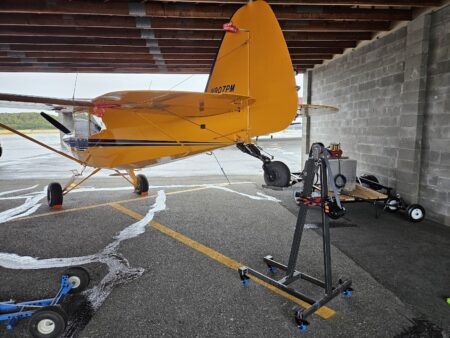
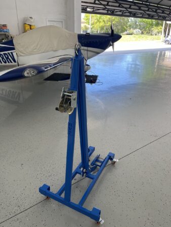
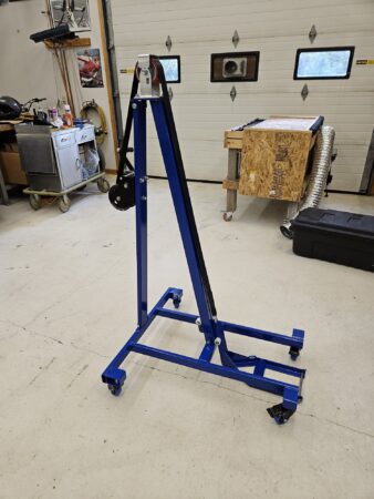
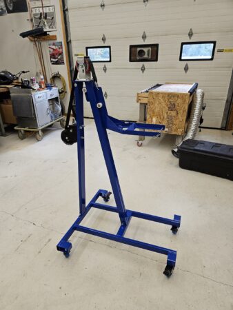
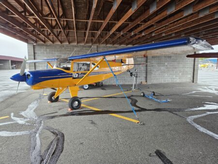
After that 10ish hours without an engine failure I figured it was time to spread my wings a bit and do a little cross country, at full power of course. I was flying in familiar territory. In my beautiful part of Alaska there are a BUNCH of airstrips available in case of an unfortunate event. Almost all are private, but I have yet to meet anyone that would not welcome a pilot in immediate need of a short, semi-flat surface. So my next 15 hours were spent doing cross country flights, at altitude, at close to full power. At 25.4 hours it was time for a another oil change and a good look over of the airframe. In addition to the oil change, I did a mini condition inspection as most of the important parts on the airframe and controls are hidden behind panels and can’t be seen on a preflight. I built a tail stand and calibrated my oil dipstick in the 3pt attitude and verified the factory stamped level attitude markings.
So what are my takeaways and what did I learn? First and foremost I always did a good preflight and a very thorough post-flight after every flight. On one post-flight I discovered the inlet fitting of the oil cooler started leaking. Everything stopped until it was fixed. I also maintained a meticulous log of the engine parameters. Even at the top end of the performance envelope, flying in circles can get pretty boring. Every flight I recorded the OAT, engine oil temperature, oil pressure, each cylinders EGT and CHT (Number 2 has always been my hottest), fuel flow, volts and amps. During my cross country flights I experimented with how minor trim settings affected level flight and always tried to keep my altitude within 50 feet of my target altitude. BTW, my BH can be trimmed to fly hands-off in smooth air, no heavy right wing as some have experienced. I feel very fortunate in that area. I also have a real-time CO detector in the cockpit and I recorded those readings as well. I never saw more than 1 PPM in level flight and 8 PPM maneuvering. I also took note of the differential between the level of the fuel tanks after refueling. I always flew with both tanks selected and never had more than 1 ½ gallons differential between the two at refueling.
One thing that took me off-guard a bit was making the transition from fabrication mode to maintenance mode. I built this thing, now I have to maintain it. It’s a completely different set of skills! I started a list of deferred maintenance items to “fix” during my next condition inspection. They are all minor, but should be resolved.
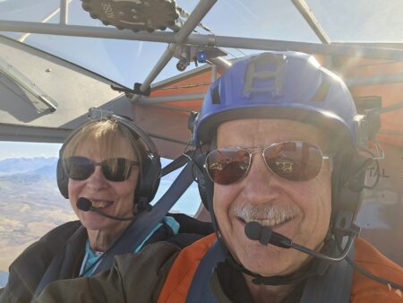
Now that I am satisfied that the engine is broken in and the aircraft doesn’t exhibit any control anomalies, I will start and complete the EAA flight test checklist. I feel it is very important to do the methodical testing and documentation of the aircraft. But, like I said before, this is a tried and true design and the first few hours didn’t exhibit any builder-induced surprises, so I was comfortable in getting the engine properly broken in before going any further. As an aside, I legally took up my first passenger the other day…my wife! The day was stunning. It was completely clear, light wind and the fall colors of the birch and aspen against the turquois blue of the Kenai River were amazing. Even Denali (formerly Mt. McKinley) was in full view in spite of it being over 150 miles away. “Don’t give in, don’t give up.” – Iwai Makoto

Control Locks:
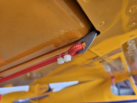
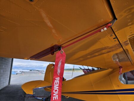
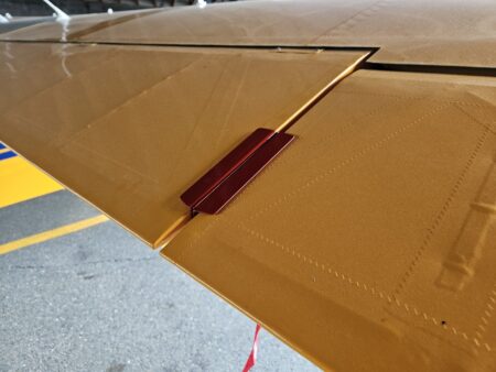
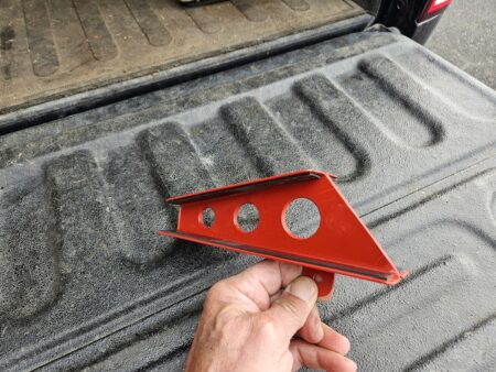
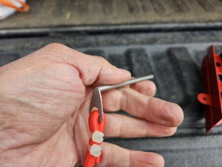
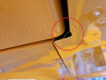
I want to share what I made for the 4-place BH. Yes, they look almost identical to the Atlee Dodge gust locks because that’s where I got the idea from. I would have bought them from Atlee, but I wasn’t sure if the profile angle of the Piper aileron/flap matched the angle of the BH control surfaces. Also, the bungees holding the Atlee locks in place wrap around the lift strut of the Piper. That isn’t an option for the BH as the lift strut is way out of alignment with the aileron/flap intersection. I looked at ways to attach a bungee and almost settled on drilling a hole in the bottom of the wing somewhere close to the edge and installing a small eye bolt. I spent a lot of time just thinking about options when saw a little hole in the wing that is created by a stiffener that is riveted to the trailing edge of the flap pocket. I tried out different diameters and lengths of rods and found one that slid in and out without any trouble.
I made the pins and the eyes welded to the end of the pins out of stainless steel so they wouldn’t rust. I made the locks themselves out of some scrap .060 5052 that I had in my now vacant shop and glued some neoprene strips on the surfaces that contact the fabric. A couple of red bungees, flagging and some zip ties later I have a set of gust locks!
I have a set of Air Gizmos gust locks that I was using for the flaps, but I had to still tie the stick back. Also, there were a couple of times I found the gust lock on the ground when it had worked itself loose. The Air Gizmo lock works great as long as the surfaces are close to parallel. So instead of buying another set for the elevator, I made these and am now using the ones I had for the flaps on the elevator. Now everything is tight and I don’t have to use the seat belt to tie the stick back.
Tail Lift:
In-Flight Flap Deflection Measurement

Source: 2023Q3 Beartracks, Russ Erb
Starting in the mid-1990s, the Bearhawk was first introduced to the homebuilt scene when Bob Barrows, the designer, would famously park the prototype at airshows such as AirVenture and Sun ‘n Fun with the flaps full down. It was an impressive sight with those long span flaps deflected down 50 degrees. “Everyone knows” that flaps allow an airplane to land slower and thus shorter. If you are trying to sell a design as a STOL airplane, showing a lot of flap is certainly one way to do it. (Personally, I built the airplane because it was a high wing four place, not because of STOL back country capabilities. The wheel pants give away that this airplane mostly lands on pavement.)

Figure 1. Bearhawk parked with flaps full down


The reality is that the flaps don’t actually deploy that much while in flight. While the actual deployment is sufficient, as we will discuss later, it just doesn’t look like it does on the ground. Anyone who has flown a Bearhawk with the flaps deployed and bothered to turn around and look at them while airborne will notice the difference. It also turns out to be a good thing that the flaps don’t deploy any more than they do.
A while back, Jared Yates was talking with Bob Barrows about how much the flaps actually do deflect while in flight. They both knew it was less than the flaps deflect on the ground, but no one had ever actually measured the deflection. Seeking to find out, Jared contacted his favorite Bearhawk flight tester to investigate this issue and find out what we could learn about it.
I had always assumed the difference was because of “cable stretch” but hadn’t bothered to actually investigate this hypothesis. Now that someone else was asking the question, it was time to design a flight test program.
The Difference Is Visible
Since you may not have your own Bearhawk to go fly and see for yourself, let’s take a look at some pictures taken during our flight test. Each of these pictures is taken the with the camera in roughly the same position, so you can compare the pictures directly.
In Figure 2, the flaps are three notches down on final approach at 65 KCAS, which is supposedly 40 degrees of deflection. Note the size of the gap between the trailing edge of the flap and the trailing edge of the wing root fairing and compare it to Figure 3.
In Figure 3, the flaps are three notches down, but with the air loads removed. Notice how much larger the gap is between the trailing edge of the flap and the trailing edge of the root fairing compared to Figure 2. This very noticeable difference in deflection in the air and on the ground for the same flap lever position is what led to this investigation.

Figure 2. Three notches of flap at 65 KCAS


Figure 3. Three notches of flap at 0 KCAS


Flight Test
The test item for this test was Bearhawk #164 “Three Sigma”, which is a four place Bearhawk of the original design (Model A). The flaps of the Model A stopped at a wing root fairing about 12 inches from the fuselage. Later Bearhawk designs have flaps that extend right up to the fuselage.
The flaps were mechanized in a Piper style design. A flap lever pulled a cable, which pulled an arm on a torque tube at the wing root, and another arm on the same torque tube pushed a pushrod that deflected the flap. Flaps were held up/pushed up by air loads (lift) in flight, and were held up by springs while on the ground. The flap cable ran from the flap lever by the pilot seat, underneath the floor, and up behind the rear cabin bulkhead. Through a fitting and three turnbuckles, the flap cable formed a “Y” with the upper two branches running to the top of the fuselage and forward to each wing root, where they attached to an arm on each torque tube. The total length of cable from the flap handle to the torque tube arm, minus fittings and turnbuckles, was approximately 172 inches.
Results
The measured flap deflections are shown in Table 1 and in Figure 4. (Flap deflections measured at flap limit airspeeds)

Notches Nominal Deflection Degrees Ground Degrees Flight Degrees
0 0 4.3 -1
1 15 14.6 2.2
2 25 29.1 6.4
3 40 42.8 17
4 50 55.1 N/A


In Figure 4, the black dots show the nominal flap deflections, i.e. the values shown on the plans.
In-flight data at four notches of flaps were not collected, because at an airspeed of 55 KCAS I was not able to pull the flap handle more than about halfway from the third notch to the fourth notch because of high aerodynamic forces. Tests later with a force gauge estimated that the required force to pull on the last notch of flaps was in excess of 75 pounds, which was more than my (apparently wimpy) arm could pull. I tried multiple times with no success. I do not routinely use the fourth notch of flaps, but I have been able to deploy it in flight on a previous occasion. I don’t know what was different this time. Bob Barrows told me he has to slow to almost stall speed to get the fourth notch out. I’m not sure how smart that is close to the ground. He also said the new arrangement with the flap lever raised from the floor makes this somewhat easier by changing the muscle groups required.
The most significant thing seen in Figure 4 is that the in-flight deflections are around half of what was expected based on the ground results. This is consistent with what we saw earlier in Figures 2 and 3.
On the ground with no air loads, my flaps have a resting deflection of 4.3 degrees while the flap lever is in the zeroth notch. I made this adjustment years ago when I realized that with the flaps adjusted to have the trailing edge line up with the wing root fairing on the ground, airborne the flaps did not move at all when pulling to the first flap notch. Thus, I shortened the flap cable slightly so that the flaps would actually move slightly at the first notch. In flight, the air loads push the flaps up to the up stop, stretching the cable as required.
Bob Barrows told me that when designing the Bearhawk, he expected that the actual in-flight flap deflection of the flaps would be less than the deflection seen on the ground. He also expected that the flaps would deflect more as the airplane slowed down because of lessened dynamic pressure, causing the flap drag coefficient to increase. The flight test we did was only done at the flap limit airspeeds so as to capture the minimum deflections.
Analysis
My first suspicion was that the flap cable was stretching under load, resulting in reduced flap deflection. There are two ways stranded cables stretch when under load: elastic stretch and structural stretch. Elastic stretch refers to stretching caused by elongation of the wires in the wire rope. That is, the metal strands act like a really stiff spring. Conversely, structural stretch is caused by the adjustment of wires and strands, lengthening of rope lay, and compression of the core. Structural stretch is the larger of the two by roughly a factor of 10. Even so, the structural stretch should be less than 1 percent of the total cable length.
Can 1 percent stretch or less explain the difference seen in flap deflection? Yes it can. Because of mechanical advantage, the cable doesn’t move much when the flaps are deflected. The cable is about 172 inches (over 14 feet) long, so 1 percent is over an inch of stretch. A more detailed analysis predicted a total cable strain of just under 1 percent, as expected. (Bob notes that twisting of the Flap
Torque Tube also accounts for some of the system flex).

This article is a summary of the results. For the full story on how this test was done and the full analysis, go to http://erbman.org/trailingedge/2308%20in%20flight%20flap%20deflections.pdf.
Can We Do Better?
If by “better” you mean get more in-flight deflection, then probably not with the current design. But I contend that there is little to be gained with more deflection.
The aileron control cables and elevator control cables are each a complete loop, which we pre-tension with turnbuckles. This absorbs the structural stretch in these cables so that we can then make precise control inputs. With no other guidance to go by, I adjusted my cables such that when the control surface hit the stop, I could not push the control stick enough (with a reasonable force) to cause slack in the return cable. Knowing what I have learned in this investigation, I feel confident saying that I put enough tension into the cable to use up all of the structural stretch, leaving only the elastic stretch.
There is no pre-stretch in the rudder cables other than what you put there with your feet because the cables are not a complete loop. This is acceptable because, unlike the elevator or ailerons, there is no significant aerodynamic lift on the rudder in its neutral position, and the required precision of control is less.
The cable that we use for the flaps is not pre-stretched, which is apparent because you can grab the strands and easily untwist them. The Bearhawk flap cables don’t see enough tension for the structural stretch to take a set, which allows the cables to remain flexible, which is important when pulleys are involved.
You could always shorten the flap cable to get more in-flight flap deflection, but this will cause two problems. First, depending on how much ground deflection you add, you may add enough that the cable won’t stretch enough for the flap drive to hit its hard retracted stop, meaning that all of the flight loads on the flap will be carried by the flap handle mechanism. Second, doing this preloads the flap system, so it will take even more force on the flap handle to move the flaps into the desired deflection.
My operational experience would point to the conclusion that the flaps are fine as they are. My investigation into the best configuration for an instrument approach showed that two notches of flaps was the minimum deflection needed to control airspeed for the final approach and landing. For 13 years I have generally used three notches of flaps for final approach, which allows for a slower approach speed and produces sufficient drag to maintain an approach angle steeper than the 3° ILS/PAPI/VASI glideslope if desired. Yes, the flaps don’t deflect as much in-flight as the plans claim they do, but the actual deflection is sufficient for the mission as designed. Thus, no changes are recommended.
Besides, full flaps still look cool at fly-ins.

Modifying the Flap Handle for Easier Access with a Rope

Source: 2022 Q3 Beartracks, Russ Erb

Bob Barrows is a tall man. With height comes long arms and long legs. Since the RB-4, the airplane that would become the prototype Bearhawk, was expected to be a one-off airplane for his own use, he understandably designed it to fit himself.
I’m only 5’ 9” tall, which is a reasonably average size. While building my Bearhawk, I moved the rudder pedals 3 inches closer to the seat than shown in the plans, which still puts me most of the way forward in the seat. My reach to the stick and panel has been quite acceptable. What I’ve had trouble with for the last 14 years was reaching the flap handle, especially for the first two notches of flaps. To reach the release button with the flaps fully retracted requires bending over enough to put my face in the instrument panel, which isn’t really good for flight safety. This was partially mitigated by ramping the first two notches so that I could pull the handle up without reaching the release button. Even so, it still required an uncomfortable amount of leaning forward to reach the handle. Once the flaps are down two notches, I can reach the flap handle and release button reasonably comfortably.
The Search for a Solution
So, for years I’ve been noodlin’ trying to come up with a way to actuate the flap handle more safely without having to stuff my face in the instrument panel. One guy I know was actually marketing a product for just this purpose. It consisted of a second handle above the flap handle for pulling it up and a mechanism for actuating the button so that the handle could be moved up and down. He sold his product for several types of aircraft, and asked for access to my Bearhawk so that he could design a similar product for the Bearhawk. Because of the unique geometry of the Bearhawk, any auxiliary handle he tried collided with the seats when the flaps were at higher deflection. After two or three attempts I think he gave up, as I haven’t heard from him again.
As I continued thinking about possible solutions, I realized that the biggest problem was trying to figure out a method to remotely depress the flap handle release button. After much consideration, I realized that I didn’t really need to be able to remotely depress the flap handle release button. I do all of my takeoffs with the flaps retracted, since the takeoff distance is not significantly reduced with flaps extended. The airplane would rapidly accelerate above the flap limit speed before the flaps could be retracted unless the nose was pitched uncomfortably above the horizon. Stuffing my face in the instrument panel to retract the flaps while still very close to the ground didn’t seem like a safe thing to do. While this sort of risk may be justified from short back-country airstrips, it was not justified for my style of runway to runway flying.
Otherwise, anytime I would retract the flaps would be at a high enough altitude that I felt safe enough briefly stuffing my face in the instrument panel, or else I was safely at a stop on the ground. Therefore, I could get by with only a system for lowering the flaps the first two notches. After that I could actuate the flap handle normally.
I had seen some other builders that had welded a simple handle about three inches above the flap handle. This would still require a significant amount of bending over. If the handle were high enough to reach without bending over, it would interfere with the seats at higher flap deflections.
The Epiphany
While sitting in my Bearhawk trying to figure out a suitable solution to this problem, I realized that I didn’t need a rigid handle. All I needed was essentially a rope tied to the flap handle and a handle to pull on. I would also need some method for keeping the handle where I could reach it so I wouldn’t have to reach down to the floor to pick it up, which would defeat the whole purpose.
I first tried tying the cord down near where the sector goes through the flap handle. Flight testing showed that I could pull on the first notch of flaps, but there wasn’t enough leverage to pull the second notch of flaps. Thus, I modified the design to pull near the end of the flap handle for more leverage. In this configuration I was able to successfully pull on the first two notches of flaps in flight, so it was ready for the final design.
The Final Design
The final design is as shown in the photo on the previous page. The pull handle is way over the top from what is needed. My handle was originally the D-Ring for an Air Force high speed ejection parachute as used in the T-38. Back in 1981 I was a survival instructor at the US Air Force Academy. Two groups of students each cut up a condemned parachute pack to use the materials to fabricate various pieces of improvised survival gear. I saved the parts they didn’t use, and have had them in a box for over 40 years, hoping someday I could find a use for them. In this case, I found a use for at least one piece. In reality, a 3-inch piece of 3/4 inch dowel would have worked just as well.
A simple piece of 550 parachute cord is sufficient to connect the pull handle to the flap handle. The fancy overbraiding with cobra knots is strictly aesthetic and adds nothing to functionality. I just like doing that. A smaller cord is used to hang the pull handle from some convenient structure above. This keeps the pull handle where it can be reached. A carabiner allows easy release from the structure above if needed. A piece of 3/4 inch PVC pipe (from the aircraft supply section at Home Depot or Lowe’s) goes over the flap handle, and keeps the pull cord from sliding down the flap handle. The PVC pipe is restricted from sliding down the flap handle by the welds around the opening for the sector. The geometry of your arm pulling on the third and fourth notch of flap will tend to cause the PVC pipe to be pulled up over the end of the flap handle. This would not be good. To prevent this, a slot was cut in the side of the PVC pipe and a screw clamp was placed at the lower end to securely clamp the PVC pipe to the flap handle and prevent pulling it off.
Finally, a small screw clamp is placed at the end of the flap handle, just below the release button, to keep the pull cord from sliding off the end of the flap handle. Carefully position the clamp so that it doesn’t interfere with your hand as you are pulling on the third or fourth notch of flaps.

Inboard Flap Extension – Pre-Model B Bearhawk 4-Place

Source: 2022 Q2 Beartracks, Mark Scott
An empty winter basement with no projects underway is a dangerous thing.
It is great fun flying my “A Model” Bearhawk 4-Place to wonderful out-of-the-way places with short grass strips. Short field performance is great, especially with 260 hp installed, but I knew if the flaps were extended inboard it would do better. I applied my professional aerodynamics experience and calculated an expected 3 kt reduction in power-on stall speed with flaps extended inboard close to the fuselage.
Three knots might not sound like much. But landing roll distance is dictated by kinetic energy which is: ½ *Mass * Velocity squared. This is why brakes are often rated by energy dissipation capabilities. For example, a touch down speed reduction from 35 kts to 32 kts is a 16% reduction in kinetic energy which means a 16% reduction in landing ground roll for the same braking power. That would drop your 500 ft roll to 420 ft. I have a time integration program that calculates airplane takeoff roll that shows the same or slightly larger percentage reductions in takeoff roll.
The 3 kt power on stall speed reduction from only an 11 inch inboard flap extension is derived from three things. First the flap area is simply bigger which of course helps. The second and biggest benefit is the new flap area is in the propwash which generates a couple times more lift than if it were not. The third benefit is the close proximity of the inboard flap end to the fuselage creates resistance to the air escaping from the high pressure lower surface to the upper surface. This further increases flap effectiveness. Hence, inboard flap
area is very valuable. All the newer Bearhawk models as well as Maules, Huskies, and other high wing aircraft have flaps running close to the fuselage so I was pretty sure there would be no adverse directional stability or control issues.
Figure 1 shows the original flap configuration. The fixed portion trailing edge is slightly longer than at the hinge line.

This geometry makes the flap to fuselage gap decrease as the flap is deployed. The inboard portion of the fixed section is removable via Tinnerman screws in nut plates for access to the flap cable, guide, and pulley.
Figure 2 shows a true straight edge hardwood board clamped to the wing at the cut line.

I used an air powered grinder tool with a thin 3/32 cutting disk. I found the thinner disk made for a cleaner and easier cut. The outboard rib is cut and trimmed back to the spar as far as possible but the inboard rib is not cut. The plan was to leave the rib attached to the rear spar and bend it inboard parallel to the top fuselage longeron. You can’t run the flap immediately adjacent to the fuselage because of the flap cable guide and pulley.
Figure 3 shows the left side rib bent parallel to the fuselage longeron.

You have to drill out some wing skin rivets at the front to enable the bend. Figure 4 shows the completed much narrower fixed portion.

I was able to reuse the original fixed portion skin by trimming it to match the new rib location and drilling it to match the rib’s Timmerman nut plate locations. With the new narrow fixed portion location set I made a cardboard mock up of the flap extension. Cardboard is wonderful stuff for making aluminum mockups.
Figure 5 shows a trial fit.

This mockup was invaluable to laying out the new inboard flap skins.
Figure 6 shows the right flap extension in work.

Conventional aluminum design and fabrication techniques were used. The inboard rib and skins are .024 inch and .020 inch 2024-T3 respectively. A simple stress analysis on the attachment rivets found the .020 skin more than adequate. There is a .016 in thick center rib to eliminate potential thin skin oil canning vibrations that could develop in the pulsating propeller wake. The skin is one piece with a semicircular trailing edge to match the flap. I used flush 1/8 pull rivets throughout the assembly including the attachment to the flap.
Look carefully at the left flap extension in Figure 7.

This is where it got a little tricky. I reflex my flaps about 5 degrees up in cruise. This places the flap leading edge very close to the rear spar. With the mockup I found interference between the leading edge of the new inboard flap section and the rear spar. In particular a rivet head at mid-section, and the rear spar attachment doubler plate and a rivet at the inboard section. I had to bring 4.25 inches of the most inboard section in about 3/16 of an inch for clearance. I made two additional holes for rivet head clearance. The craftsmanship does not have to be exceptional here since it is always hidden. It just needs to be structurally sound and fit well.
Figure 8 shows the completed left flap extension riveted to the flap inboard rib.

It took a few tries to get the flap contour to nicely match the flap rib but it worked out in the end. It also took a couple of iterations with the flap extension clecoed to the rib to check flap clearance and trim to the new fixed portion. Once installed I carefully laid down lines for the dark blue stripe and made templates. Fortunately, a friend started painting his Kitfox and built a beautiful paint booth. I used that to complete the painting. The final result is shown in Figures 9 and 10.


So, were my calculations correct? It looks like they were. My power on stall speed dropped from 32 Kias to 29 Kias, plus or minus 0.5 Kias, at the same gross weight and CG. I have not been able to do takeoff roll measurements yet but it feels shorter. I think the flaps look a lot better too. I reduced my flap extension speeds by 5 Kias due to the larger flap loads.
The indicated stall speeds are lower than expect based on calibrated airspeed calculations. I suspect some kind of upwash at the pitot tube is going on since Cessnas have a large Kias to Kcas calibration factors near stall and I have a similar pitot tube installation. Subsequent and ongoing airspeed calibration runs with a yarn tuft rake shows a lot of upwash. This may the subject of a future Beartracks article. In
any event the difference in speed between the flap configurations should still be fairly accurate since my measured pitch attitude is very close for both configurations.
If you have interest in performing this modification I would be happy to talk to you about the details.

Installing Aileron and Flap Hinges

Source: 2022 Q1 Beartracks, Bruce Case
Installing the hinges on the ailerons and flaps requires a methodical approach to turn out well. Here is the method that worked out for me. I first made two jigs to aid in drilling the aileron and flap hinges. The first jig shown here allows me to precisely locate both the bolted mounting holes and the hole which the ailerons and flaps pivot about. I used hardened drill bushings in my jig but you could simply do this with a large piece of angle iron. Just be careful that your drill is perfectly perpendicular to the hinges when drilling. What is most important is that you create the hinge pivot hole in all hinges at exactly the same distance from the mounting face of the hinge. The jig will guarantee this. If these holes are not precisely placed the hinge pins will not all be perfectly horizontal and binding of the aileron or flap can result. The locations of all the holes are called out in the plans.


Above is a picture of the jig in action. I use clamps and a vise grip to securely hold the hinges while pilot drilling the mounting holes with a #30 drill. I then pilot drill the hinge pivot holes with a #16 drill and then open up the pivot hole to the final dimension using a .188” ream which is the perfect hole size for a good fit on an AN3 bolt.

The photo above is my second jig in action. This jig precisely locates the location of the rod end bearing hole in both the long arm aileron and flap hinges. These holes are pilot drilled with a #16 drill and then reamed to .188” for an AN3 bolt.

Above is the hinge after drilling the rod end bearing hole. All necessary holes have now been placed in the hinges.
The hinge mounting procedure is the same for both the flaps and ailerons so I will only illustrate the aileron here. Note that the hinges will be offset in their pockets. This allows easy insertion of the hinge bolt. The plans call out an 1-3/8” centerline location for the hinges. Make a .628” wide aluminum spacer. Taping this to one edge of the pocket will give the necessary 1-3/8” centerline dimension when the hinge is butted up against it. Refer to the plans for the correct location of the 1-3/8” dimension as you don’t want to tape the .628” spacer to the wrong edge. You will only use the .628” for the first pocket as the location of the second set of hinges is governed by the 2nd steel pivot bracket attached to the spar:

The aileron is located flush to both the top and bottom sides of the wing using two contoured wood templates. I made this template using the wing Mylar airfoil plot furnished with the plans. Note you will want to create a little additional space at the rear of this wood pattern to allow the aileron some latitude in front to back positioning. It is important to clamp the wood pattern firmly to the wing so there is no gap. You will have to start out with this wood template slightly loose to allow for moving the aileron around to the
correct position:

Select the correct hinge bracket and place it against the spar and the .628” aluminum spacer previously taped down. Insert the longest AN3 bolt that you can install in the hinge. I found that an AN3-11 was perfect.
Now apply pressure so that the hinge is firmly pinched against the .628” aluminum spacer and then move the two wood wing templates into position so that they are tight against the wing and the aileron. This takes some time but can easily be done by one person. The goal is to have the hinge tight against the .628” spacer and tight against the spar. The wood template will force the aileron into the correct location. Now with everything held firmly move the hinge up and down so that the AN3 bolt is perfectly horizontal when sighting from the rear of the aileron. The hinge is now in the correct position for drilling the first hole. I secured it firmly in position using a ¾” piece of wood and a small C-clamp at the bottom of the hinge before drilling (photo below).

Using a right angle attachment drill a #30 hole in the top hole location only (photo below).

Now remove the aileron from the wood wing templates and carefully open up the #30 hole you just drilled to the correct size for a #6 screw. Mount the hinge using a short #6 screw and nut. Remove the C-clamp holding the bottom of the hinge and firmly holding the hinge in location against the .628” spacer drill the bottom hole to a #30. Enlarge the hole just drilled to a #6 screw and attach using a second #6 screw and nut. This first hinge is now securely located.

Make a wood spacer block that is .288” thick. This is the required gap to just clear the hinge bearing. Insert the AN3-11 bolt into the hinge hole as a visual reference. Insert the 2nd half of the hinge bearing into position. Now move this hinge up and down to get the AN3 bolt as horizontal as possible. You can do this visually by sighting along the rear of the aileron. With the 2nd hinge in the correct location use a clamp to firmly hold it in position. You can also add a vise grip as I have shown in the picture to the left for more clamping power. Now pilot drill both holes with a #30 drill. Enlarge all the holes for #6 machine screws and then attach the second hinge half with #6 hardware.


At this point you can use the same procedure to drill and mount the second set of hinges at the other end of the aileron. Again use the two wood wing templates for positioning the aileron vertically. This time you will not use the .628” aluminum spacer but rather you will locate the first half of the hinge visually so it is perfectly vertical and parallel to one side of the aileron pocket and snug up against the 2nd hinge bearing. Again use the two wood wing templates to firmly push the aileron into the correct position. This second operation takes more time than mounting the first hinge in the first pocket as you don’t have the convenience of the .628” spacer. When everything is located draw a reference line using a small Sharpie along one edge of the hinge. Drill the first #30 hole as on the first hinge set with a right angle drill. Remove the aileron from the wing. Mount the hinge using the hole just drilled with #6 hardware and then using the Sharpie reference line, locate and drill the second #30 hole in the hinge. Enlarge that hole and mount the hinge with a second set of #6 hardware. Now using the .288” wood spacer locate the mating hinge and again use the AN3-11 bolt to visually get the correct vertical location of this 2nd hinge half. Drill and mount the 2nd hinge half using the same procedure as outlined in the first pocket. Reinstall the aileron on the wing and check for correct location and freedom of movement. At this point you will remove all the hinges and enlarge the mounting holes to .188” first with a drill and then final reaming to .188”. All the #6 hardware holes in the spars will also get enlarged to .188” in preparation for riveting on nut plates.
Below you can see the finished 2nd set of hinges mounted with AN3 hardware and also showing the required joggle to create clearance for the Aurora rod end bearing.

Updates from Bob, 2021 Q2

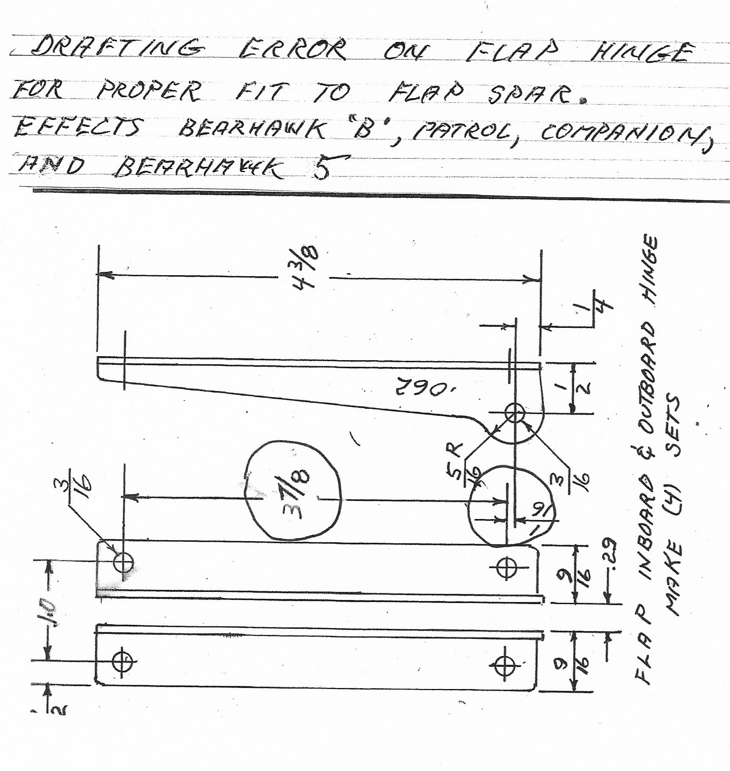
There have been two recent safety updates. The first was a minor drafting error in the flap hinge, which impacted the Model B 4-Place, Patrol, Companion and Five, and was distributed in April. This photo shows the revision:

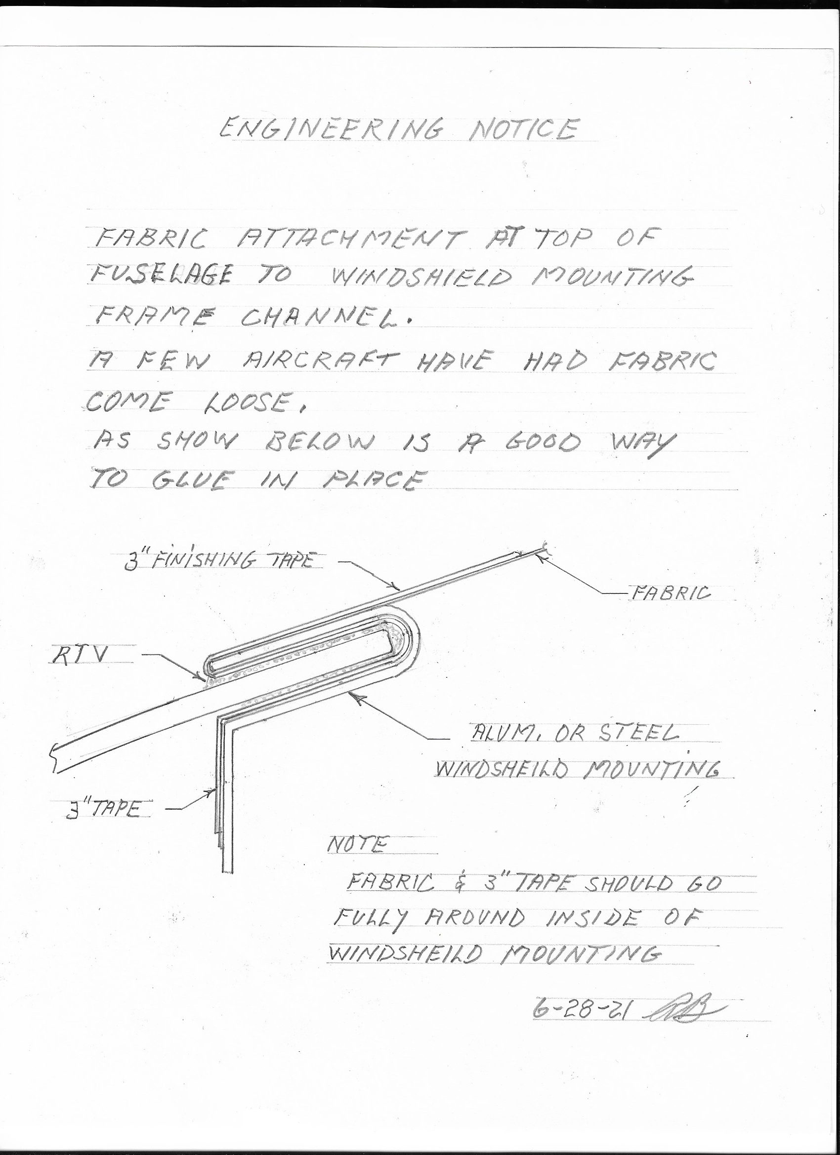
There is also a new update released 6/28/2021, which will also show up at bearhawksafety.com in the coming days. This is an Engineering Change that relates to the way the covering is tucked into the channel at the top of the windshield.
Bob’s instructions are, “Fabric attachment at top of fuselage to windshield mounting frame channel- A few aircraft have had fabric come loose. As shown is a good way to glue in place.”

If your fuselage is already covered and isn’t routed as shown in the update, he says, “If it has been flying for a while, it should be fine, but it is something that we need to let people know about.” Bob also brings up the point that it’s crucial to follow the instructions of the covering system that the builder selects. Popular systems including Polyfiber, Stewarts, and Oratex vary greatly with crucial details. In a recent case, reinforcing tapes were able to peel up with fingernail intervention, which prompts Bob to bring up that point.
Bob and Mike have been busy building engines, trying to reduce the lead time which has grown long due to strong demand.
His Bearhawk LSA is back to flying status, thanks to builder Collin Campbell in Missouri. Bob flew the airplane home and was pleased to report it flies straight after the extensive rebuild. Some of the original engine parts fly again in the new plane. Continue reading

Using Clip-Lock Turnbuckles

Source: 2020 Q3 Beartracks, Rob Caldwell
Turnbuckle Conversion Table
Builder Rob Caldwell has been making fast progress on his Bearhawk 4-Place. He’s installing MS Clip Lock turnbuckles instead of the older style AN turnbuckles that are secured with safety wire. This table shows the part number conversions for folks who might like to do the
same. The center column shows the traditional safety wire turnbuckle parts, and the right column shows the MS Clip-Locking style.

Type Safety Wire Clip Lock
Outer Ailerons (AN130-32L) 2 ea.
Barrel AN155 MS21251-B5L
Fork Eye AN161 MS21252-5LS
Cable Eye AN170 MS21255-5RS
Cabin Center Aileron (AN130-16S) 1 ea.
Barrel AN155 MS21251-B5S
Cable Eye AN170 MS21255-5RS
Cable Eye AN170 MS21255-5LS
Flaps (AN130-16S) 2 ea. (same as outer ailerons)
Barrel AN155 MS21251-B5L
Fork Eye AN161 MS21252-5LS
Cable Eye AN170 MS21255-5RS
Elevator (AN135-32S) 2 ea.
Barrel AN155 MS21251-B5S
Pin Eye AN165 MS21254-5RS
Pin Eye AN170 MS21255-5LS

Garage Engineering Episode 2: Oh Scrap!

Source: 2019 Q4 Beartracks, Mark Johnson
“They’re all practice.” — John Denver
My shop is filled with jigs and tools that have accumulated on shelves, drawers and bins over the years. As many of you know I’m building slower than slow, all because I have a lot to be grateful for: I work full time, I value my sleep, I’m a first time builder, from scratch, and I have a family. So things tend to sit a while in my garage, but I always seem to return to them and have to relearn a few things.
Such was the case when I realized I mis-drilled an aileron skin to the nose ribs. My spar was bowed more than my comfort range, but I didn’t notice until after I had drilled and clecoed the center skin to the nose ribs, forever locking the spar in a bow. This meant that once the spar was straightened out, either the skin or the ribs would have to be scrapped. It takes an act of congress and a bit of schmoozing for me to run off to my buddy’s bending brake to rebend a skin, plus that’s a lot of material to scrap. So I looked at my old rib fixtures, dust and acetylene soot and all, and ended up revisiting my first year of building to remake two aileron nose ribs.
Through the process, I was amazed at the mental games I put myself through, even though these parts were relatively simple and small. “That’s what, ⅛ inch off? Pfft no big deal.”… “Years from now, your airplane might never fly trimmed, and you will always think back to this day and curse yourself for making a bowed aileron!” … “Will it really matter? Surely it’s good enough. We’re not building the space shuttle. I’m sure the other side ain’t perfect either” and on and on it goes. I don’t think I ever made a conscious choice to scrap the ribs, until there were two shiny new undrilled ones in my hand. That makes the decision easier!
You could say I hurled myself into action before I could think much more about it. In the end, rebuilding a part was not very hard. I’d made the thing before, and all the tools and muscle memory eventually rose to the occasion. In fact it was actually fun creating something I already knew how to make. You feel like a pro. The biggest hurdle was the nagging feeling of going back; the turning away from relentless progress with ever increasing distance between me and my goal that will validate my life’s purpose, social status, marriage, sex appeal and career ambitions.
Whatever ridiculous feelings I had, they didn’t change the reality of the error that started it all. Those wandering #40 holes were still there, they needed to go away, “moving” them by drilling out to #30 wasn’t going to make up for it, and there was one obvious solution in a future universe where those mental games and compromises did not exist. I just had to do it. So moving backward was in fact the quickest path to progress.
The next time you need to scrap a part, be on the lookout for psychology taking the reins. Bob even noted in his builders book it’s not that hard to mess up and scrap a spar. A SPAR, can you imagine? When you wish you could uncut or undrill something, take a break from the task, put the knife down, breathe, get some advice and do your best to understand the problem.

Patrol: Installing the Flap Handle, Cables and Pulleys

The first thing to do is assemble the flap handle actuating tube, it is a simple matter of inserting the spring and tube inside the larger flap handle tube,(A). Builders often start with a spring that is too long and snip the spring off until the desired button pressure is achieved. Then you take the curved and detented flap position part (B), and insert it through the slot in the handle, and the tube that you put inside. Then the assembly gets sandwiched in between two tubes, (C), and a bushing, (D), is slid in place to hold it. You then bolt the detented flap position part at the top and bottom. The bushing gets drilled in place with the tube, and a cotter pin inserted, just like the rudder pedal bushings. Please note that in the following pictures, some fasteners are just temporary, or have temporary nuts on them.


Cables for the flap system are galvanized or stainless steel 1/8 7×19. The first cable is made up and connected to the bottom arm of the flap handle using a cable shackle, (E). It then runs through the lower two fairleads, around the first pulley and then under and around the second pulley. Make your cable so that you have approx 10 inches of cable after the second pulley, this is when the flap handle is in it’s lowest position (flaps 0). This cable then gets attached to the bottom of a triangular plate with a cable shackle. Remember to make the cable guards for the pulleys. What you are looking for in the final installation is to have the steel triangle as close to the pulley as possible when the flaps are in the full down position. This assures max travel of the flaps.


You will then need to make up two more cables that run from the triangle plate to the flap control horn on each wing. A turnbuckle on each cable end gets attached to the upper holes in the triangle plate, this will be for adjusting the cables later after you connect to the flaps, so make sure you leave adjustment in the right direction. The cables then run up to their respective pulley’s at the rear baggage station, go forward through two more fairleads before running under the final pulley just aft up of each flap control horn.


The final attachment is connecting the cable to the flap horn with another cable shackle. Here is a place that at times a larger cable shackle is used (1/4″) to help avoid interference with the wing rear spar end. This space is very tight. So be sure your cable, the flap control horn, or any of the attach hardware do not rub on the wing rear spar end as the flap moves through its travel range.
Remember to make sure the flap control horn (at the wing) is in the flaps up position, and the flap control handle is in it’s lowest position (closest to the floor), when making up your cable lengths. The position (angle) of the flap control horn is shown on the plans with the flaps all the way UP. Measure that angle and position it as shown on the plans.

These two drawings show the flap handle assembly, courtesy of builder Bruce Case:
Flap Handle Drawing A
Flap Handle Drawing B

Final Riveting of the Flap and Aileron Trailing Edge

As delivered, the flaps and ailerons have their trailing edges temporarily riveted in place for shipping purposes. This will allow each builder to adjust them slightly if necessary so that the edges will be perfectly straight. The reference point is the root rib, since it is fixed in place and everything else has to true up to that. Don’t use the wing tip as a reference. Fiberglass parts are not dimensionally stable over time, and some early wing tips are just a little short, so it’s common to see that the aileron can’t be made to line up with it. This nothing to be worried about. The trailing edge is just pop riveted in place. Drill out those soft aluminum pop rivets and you can move the trailing edges in and out to get them lined up. When you have them where you want them, rivet them permanently using aircraft quality blind rivets.
Lining up the Wing Tip
After you have the T.E.’s of the surfaces perfectly lined up with each other and the root rib, it may be required to build up the back of the wing tip with just a little epoxy and fiberglass. One builder glassed a short length of 3/8 aluminum fuel tube to the back of the tip and faired it with Polyfil. This provided just the right radius and also corresponded to the right amount of extension required.