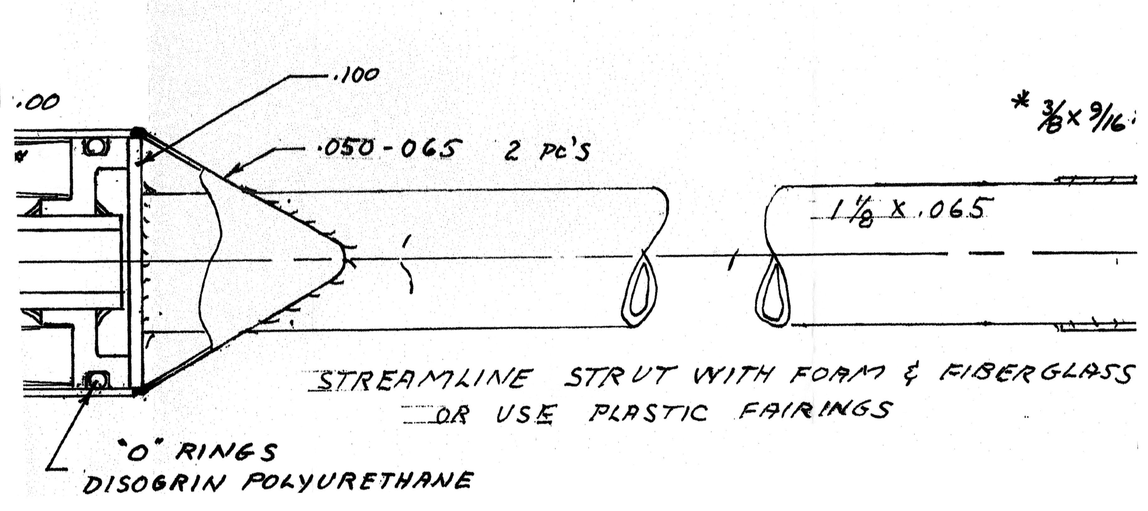
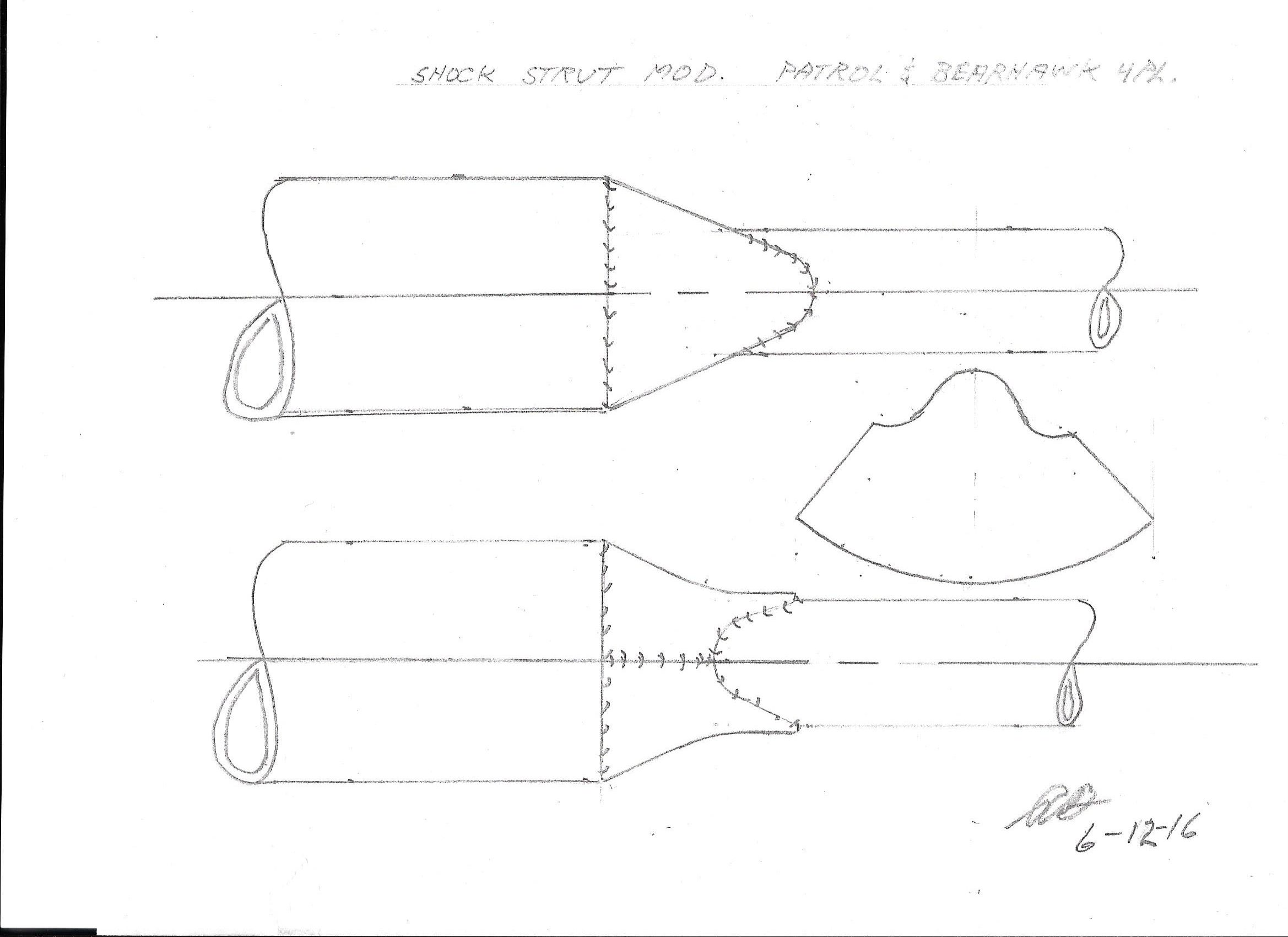
The landing gear shock strut has been changed on the 4 Place Bearhawk and the Patrol. This change was done to increase gear side load capability (ground loops) and cost reduction. The streamline tubing has been replaced with round tubing (1 1/8 x .065"). The shock strut should be faired for reduced drag.
 Safety update terminology: ENGINEERING CHANGE: A change to current serial number drawings onward - non-mandatory - may or may not be published. This change is the result of a product improvement, update or modification. Or a minor change of the design to ease manufacturing, maximize utility, economize materials or ease assembly.
Shock Strut Material Engineering Change for 4-Place and Patrol
Engineering Notice Concerning Aileron Pulley Selection
Source: 2000 Beartracks, Bob Barrows
Reference Drawing # 14 - The aileron cable pulley can be changed from a AN210-4A to the 1/2" smaller O.D. MS20220-2 if needed to allow the aileron cable to better line up with the wing strut.
If you use the MS20220-2 pulley you will need to bush its I.D. to 1/4" or use a 5/16" bolt and drill out the pulley bracket.
Inspect the line up of the aileron cable to the pulley, if not close to centered the bracket may need to be adjusted a little for proper line up.

2000 Engineering Notice Concerning Horizontal Stab/Elevator Outboard Trim Location (453 and below)
Source: 2000 Beartracks, Bob Barrows
The following Engineering Notice is Non-Mandatory. Applies to the horizontal stabilizer/elevator outboard hinge location. Drawing #20 plans serial #453 and below.
I have moved the outboard hinge to a new location 4 inches out towards the tip on drawing #20. This change is not required if you have finished fabricating your horizontal stabilizer.
Elevator spar stress levels and stiffness are improved with this running change, also the overhung ratio is more closely matched to the rudder. Upper tail wires will increase in length by 3 1/2" and lower tail wires will increase in length by 3 3/4".
Both of my Bearhawks have the original location and I do not plan to rework the tail feathers to make this change. I have had no indications of a problem to date. This change only improves the design.
1999 Engineering Notice Regarding Upper Front Door Hinge Positioning (416 and below)
Engineering Notices
Source: 1999 Beartracks, Bob Barrows
Reference plans number 416 and below, Drawing #16. As shown in the drawing below change the 5 1/2" dimension to 5 3/4" to increase clearance between door frame and bottom of the wing in the open position. If the fuselage is already welded up, adjust hinge location for needed clearance.
1998 Control Stick Engineering Notice (376 and Below)
Source: 1998 Beartracks, Bob Barrows
Refer to drawing #26 for plans serial numbers 376 and below.
The T3 control link that works inside of the 1 1/8 X .049 torque tube does not have enough clearance to use standard attach hardware as shown in view B.
Make the link as shown below so that standard hardware can be used at the cable attach locations. A 3/16" steel rivet will be need to be used at the control stick attach point. I made the rivet by cutting a AN23 clevis bolt to the 19/32" length behind the threads.


If you have already made the link you can use the AN3 bolt at the cable end with a thin nut with Loc-Tite and or peen slightly (see photo).
Another solution would be to make the .062 end brackets at an angle such that all the hardware works outside the 1 1/8 x .049 torque tube as shown above. Plans number 376 and up have this arrangement. If you would like a new drawing #26 please send $3 to cover printing & shipping cost.
The Bearhawk I am building now will use the control stick as your plans show with the 3/16" steel rivet joint at the control stick attach point. See photo above.
1998 Inboard Flap Lever Engineering Notice (280 and below)
1998 Tailplane Incidence Adjustment Engineering Change (326 and Below)
 Refer to drawing # 19.
Change the 3 7/8" dimension to 3 1/2" as shown in the drawing.
This change will allow for more horizontal stabilizer adjustment range to accommodate various engine installations.
1998 Firewall Positioning Engineering Notice (326 and below)
 Refer to Drawing # 18 firewall detail.
During the assembly of the Bearhawk I am now building I found that the 7 1/2" dimension was about 1" too high. This dimension should be reduced to about 6 1/2". See corrected drawing below.
This change is needed to keep a good line from the top of the nosebowl to the top of the instrument panel and increase the tunnel area at the bottom of the firewall for better engine cooling.
Please note the size of the firewall has not been changed, it has just been positioned lower on the airframe.
Also note that depending on the type of engine you use, the shape of your nosebowl and the height you make the instrument panel may affect the vertical location of the firewall.
The minimum clearance of the engine and related components to the cowl is 1/2".

Horizontal Strut Fittings Safety Update
Source: 2014 Beartracks, Mark Goldberg
 Applies to Four Place Bearhawk, Kits Only.
May 8, 2014
A few days ago, a customer had a failure of one horizontal stabilizer support struts in the air. Fortunately, the Bearhawk can fly without the strut on the front and he was able to land safely. Bob Barrows flew his Prototype I Bearhawk at first without the struts, but later decided that the additional safety of the struts merited installing them.
Several years back there was a change in the design of the struts at the top where they bolt to the bottom of the leading edge tube of the horizontal stabilizers. The issue was fatigue from vibration caused cracking at the place where the streamline tubing was bent at an angle to mate up to the bottom of the horizontal stabs. At that time, a change was made to run fillet weld across the area where the bend was thereby adding material and strength to the area where there had been a problem. Also, a doubler washer was welded to the bottom of the bent part to reinforce the area where the attach bolt is.
So since that time we have been aware of what vibration can do to the tail of the plane in general and theses struts in particular. The failure of this strut was in a different area. The “bolt” failed that is welded to the bottom of the strut to thread on the AN665 clevis end. The AN490 “bolt” failed where the threads ended.
Two factors contributed to make this problem occur. First, the owner reports that the welding extended past the “shoulder” of the AN490 onto the threads thereby weakening them. In addition, this strut was a little short so the owner made a longer piece to use instead of the AN665 clevis end. This positioned the end of the threads further away from the attach point at the lower longeron making vibration worse. This was a one time occurrence that no one else has seen. It is possible that the AN490 had a manufacturing or material defect despite being a certified AN fitting. We are issuing this Service Notice as a precautionary measure.
I have inspected five of the support struts – three I have on hand and the two on my Bearhawk. None have weld bead beyond the shoulder of the AN490. So it would appear that this might not be too prevalent on the parts out in the field. Please look at the picture included that shows the AN490 before welding. Where the threads transition to the shoulder is a little curved radius – it is not a sharp corner. Don't confuse this with weld bead.
We ask you to do two things: inspect that lower part of the support struts to see if the weld bead extends onto the threads. If it does, the strut will need to be fixed. Also, Bob asks that at least 1/2” of threads be engaged into the AN665. Having the threads closer to the attach tab on the lower longeron diminishes vibration and potential fatigue. The crack on the strut that eventually failed started as a small crack and grew over time. So please give a thorough inspection to this part before next flight and during your preflight inspections.
If you find that the weld bead extends onto the threads – or your struts are too short to get 1/2” thread engagement, please contact me to make arrangements to get your strut fixed. Bob has designed a fix that we will do for you if your struts are short.
Applies to Four Place Bearhawk, Kits Only.
May 8, 2014
A few days ago, a customer had a failure of one horizontal stabilizer support struts in the air. Fortunately, the Bearhawk can fly without the strut on the front and he was able to land safely. Bob Barrows flew his Prototype I Bearhawk at first without the struts, but later decided that the additional safety of the struts merited installing them.
Several years back there was a change in the design of the struts at the top where they bolt to the bottom of the leading edge tube of the horizontal stabilizers. The issue was fatigue from vibration caused cracking at the place where the streamline tubing was bent at an angle to mate up to the bottom of the horizontal stabs. At that time, a change was made to run fillet weld across the area where the bend was thereby adding material and strength to the area where there had been a problem. Also, a doubler washer was welded to the bottom of the bent part to reinforce the area where the attach bolt is.
So since that time we have been aware of what vibration can do to the tail of the plane in general and theses struts in particular. The failure of this strut was in a different area. The “bolt” failed that is welded to the bottom of the strut to thread on the AN665 clevis end. The AN490 “bolt” failed where the threads ended.
Two factors contributed to make this problem occur. First, the owner reports that the welding extended past the “shoulder” of the AN490 onto the threads thereby weakening them. In addition, this strut was a little short so the owner made a longer piece to use instead of the AN665 clevis end. This positioned the end of the threads further away from the attach point at the lower longeron making vibration worse. This was a one time occurrence that no one else has seen. It is possible that the AN490 had a manufacturing or material defect despite being a certified AN fitting. We are issuing this Service Notice as a precautionary measure.
I have inspected five of the support struts – three I have on hand and the two on my Bearhawk. None have weld bead beyond the shoulder of the AN490. So it would appear that this might not be too prevalent on the parts out in the field. Please look at the picture included that shows the AN490 before welding. Where the threads transition to the shoulder is a little curved radius – it is not a sharp corner. Don't confuse this with weld bead.
We ask you to do two things: inspect that lower part of the support struts to see if the weld bead extends onto the threads. If it does, the strut will need to be fixed. Also, Bob asks that at least 1/2” of threads be engaged into the AN665. Having the threads closer to the attach tab on the lower longeron diminishes vibration and potential fatigue. The crack on the strut that eventually failed started as a small crack and grew over time. So please give a thorough inspection to this part before next flight and during your preflight inspections.
If you find that the weld bead extends onto the threads – or your struts are too short to get 1/2” thread engagement, please contact me to make arrangements to get your strut fixed. Bob has designed a fix that we will do for you if your struts are short.