2000 Beartracks Mailbag: Q&A with Bob

Bob, Enclosed is a check for Bear-Tracks for another year. I do have a few questions:

1 – What is a good method to use to transfer the airfoil shape to the wood to be used for the form block for the wing ribs?

2 – What is the recommended radius for the wing rib form blocks? I believe that 1/8″ would be about right for both .025 and .032.

3 – Do you have an e-mail address and if so do you answer e-mail correspondence?

I have a piece of 1″ thick hard maple for the form block. I just need to transfer the airfoil shape to the wood and cut it out. I am ready to start with the ribs. Is Proto II in the air? I bet the performance is really great – Thanks for your time.

Paul Foster – #289 – Monte Vista, CO

Paul, Thanks for your questions and newsletter renewal. As for your questions

1) The best method to use is to glue drawing #7 to your form block with contact cement or Plyobond.

2) a 1/16″ radius will work best for both thicknesses of the aluminum.

3) I do not have an e-mail account. Proto II is flying great -look for a flying report in this issue of Bear-Tracks. -Bob

This letter was pulled from the Bearhawk E-group. For more information on the Bearhawk E-group see page 7.

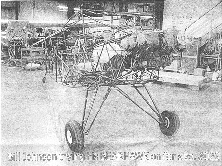
Well, after several days of non-stop building, 023 is on the main gear. I stumbled across a new Scott 3200 tailwheel in some stuff my Dad purchased from someone’s attic. He got a bunch of stuff (including a 65 hp engine, prop, landing gear, etc) for less than the price of a new Scott! What a deal.

Anyway, related to tail leaf springs, after much discussion and some consulting with Bob, I have decided on purchasing a PA25 tail spring from Univair (part number PA25TWS1) for approximately $90. 1 decided on the PA25 because Bob recommended two leafs all the way to the tail wheel bolt. Taper rod was attractive but with the Scott tailwheel, side loads should not be a big problem – it will go to full swivel if a major side load occurs.

My plan on putting a Continental 0470 on my Bearhawk has been changed. Finding an engine mount damaged or not – is not easy. Any found, even damaged, seem to run between $500 & $700. The Lycoming 0540 seems easier to make an engine mount following Bob’s newsletter. Also, Bingelis only talks about Lycomings!

Compressing the landing gear shock strut took some thought. I used a bar clamp – very long – and it worked fine. Later Bob told me he used his drill press with the table moved off center – I wish I thought of that! Oh well, some days I make things harder than necessary.

Piper TriPacer Seats also took some work to find. I ended up paying $60 each – frames in very good condition and but they need covering. Seemed like allot but finding seats was not as easy as hoped. Salvage dealers did not have any. My source has a couple more sets if anyone is interested.

Well, that’s my story for now. If anyone is near Cincinnati (actually Florence, KY) or Elkton, Ky, let me know. I build my parts in Florence and assemble in Elkton. It would be great to have some other builders close to discuss building, etc.

Bill Johnson – #023 – Florence, KY

Hi Bob, So glad to hear that you are ready (perhaps already have) to fly #2. Our second wing is going together quickly. Should have both sides, including control surfaces before the end of the year. Looking forward to starting on the fuselage.

The photo is my left wing with control surfaces installed. I am starting to look for a wind damaged Maule or C180/182 to scavenge for the engine and other needed parts. Still having a ball with the whole project.

Pat Fagan – #232 – Pearblossom, CA

Also from the Internet -I have most of the systems hooked up or at least roughed in. All the flight controls are working. I am finishing up the fuel system now. #75 is being powered by a (1996) Ford Taurus 3.0 24 valve engine that I modified with a polybelt GT. The engine has run with no propeller but hasn’t been run to RPM or load yet. Items needing to be finished are the fuel system, engine control linkages, a few things left on the cowl, and trimming everything. I am installing a removable interior for complete inspections in the future. I know that a lot of little details need to be worked out yet.

I am in the process of moving again. This time I am going to build a house and hanger at an air park. I hope to continue working on the Bear hawk through out the house project and get it in the air by at least late summer. How is everyone else doing on progress?

I will be happy to answer any questions the group has and give my opinion of what I may have done different. I will say as far as the plans I have followed them to the line and had very good results, The project gets more interesting when you start to improvise beyond the main part of the plane, i.e. engine controls and all the other goodies. Enough for now. Happy building.

Tom Yeoman – #075 – Apache Junction, AZ
Hi, Bob,
Things are moving along, not on schedule, but forward.

I was saddened to hear of Ray Thurston’s passing – It was like hearing about a family member.

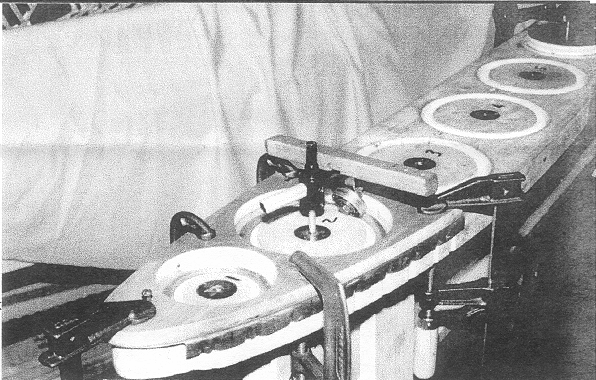
The enclosed picture shows the flanging tool I used for the rib “holes” – it was made from a standard flycutter and worked great! The wood handle was used to exert pressure on the bearing. Steel washers were glued to the form bloc to serve as bearings for the center pin. This might be helpful to other builders so I am passing it along. All the Best,

Walt Draxler – #082 – Arlington Heights, IL

Bob, I hope this letter finds you and Mike in good health and fun flying in your Bearhawks. Enclosed is a check for my newsletter renewal – I have been so busy that I forgot to send it in. I’ve finally got a good start on my Bearhawk. I have all my small steel parts cut out. I am just finishing all my ribs and I am about to start on the wing spars. My goal is to have the wings done by the beginning of winter. I am enclosing some long overdue pictures of my project. I will be looking forward to seeing you and Mike at EAA again this year. If you need a place to stay for a couple of nights you can stay at my place. I am about 40 miles from Oshkosh. Maybe that is too far, let me know. I sure would like to hear your comments about my project. I can take criticism. I hope to have the wings framed up by then. I have a question about the fuel tanks. I noticed in one of the newsletters that you weld and rivet them. Is the riveting necessary? Can I just weld them? Is the riveting for added strength or just to hold them together for welding?

Ray Gabriel – # 334 – Greenleaf, WI

Ray, thanks for the nice letter and your newsletter renewal. Your parts look very good in the photos that you sent. Mike and I might be able to stay over at your place for one night while at Oshkosh, check with us at Oshkosh. It would be interesting to look over your project. The rivets in the fuel tanks are only to hold the sheets in place for welding. ~ Bob.

Ray Gabriel using a Liebert Hole Cutting Machine. Ray reports that a user can cut all the holes in all the ribs in about 3 hours with this machine. Also pictured are all the 4130 steel and a few of the aluminum parts ready for bending and drilling.


Bob, I have been meaning to write for sometime to thank you for the information in your newsletter. I have been working on my seating arrangement. The front seats incorporate a “captain’s table” arrangement for the mounting. Adjustments are made by pulling a side lever to the right and sliding the seats back and forth. The back of the front seats fold forward to allow entry to the rear passenger area. The back of the rear seat is adjustable. I used 3/4″ x .035 square tubing for the windows and door frames. I know that it costs a little more but it sure is easy to work with. I’ve got to relocate the rear window frame 2″ higher.

The engine is a Lycoming 0-540 of 235 HP. It will be pulling a fixed pitch McCauley 8452 Prop. I hope to have it up and running by October 2000.

George Anderson – #153 – Daphne, AL

Hello Bob, Just got the Jan 2000 Bear-Tracks. I am always looking forward to receiving the next issue. Sorry that we didn’t make it to the fly-in in Oct. We were planning on coming down to the fly-in and visit relatives but I came down with the flu – so maybe next time.

Thanks for the information in the newsletter – It must be nice to have two Bearhawks!

Thank you for coming to our cook-out last summer and I hope you can make it to our next one sometime in June this year. Since the cook-out there have been 4 of my neighbors talking about building Bearhawks. My daughter and son-in-law are planning on building one as soon as they finish their Cessna 140. We might have to change the name of the airport from Hale’s Landing to Bearhawk Landing!

I have been busy working on the 1959 Cessna 172 that I am restoring – it’s almost done. The Koala 202 is almost ready to cover and I have most of the 4130 steel hardware for my Bearhawk wings made. I have too many projects and not enough time or money to finish them all.

Do you have plans for any future modifications for the Bearhawk? If so what? How about plans in the newsletter for seat frames and tracks. I have found that the Tri-Pacer seats are hard to find.

Dan Riffee – #267 – Hale’s Landing, WV

Dan, Sorry to hear that you were sick and couldn’t make it to the fly-in. Like you say maybe next year. Mike and I really enjoyed our trip to Hale’s Landing last year and are looking forward to it again this year. When you firm up a date – let us know.

Currently I have no more modifications to the Bearhawk design planned. Your idea for seat drawings is a good one and I will work on that for a future newsletter. -Bob


Bob, Enclosed is a check for the 2000 newsletter, also I have a few questions:

1) The part of the nose ribs that form the leading edge, have you noticed on the prototype or do you forsee a problem with fretting because the metal is not secured together at the leading edge tip?

2) On the plans it calls out a 1.25″ flange on the main spar and a 1″ on the rear. The newsletter has instructions for laying out spar blanks : Width = web finished height PLUS 2 x flange width PLUS 1/16″. This will give a larger flange than calls out in the plans, the same also with the 9/16″ and 1/2″ marker for the rib flanges. I wonder if it makes a difference or would I have clearance problems later?

3) Are the spar webs square on both ends or do the root ends have the shape of the wing attach fittings to fill the gap between the fittings?

I have started slowly on the wings, having trouble getting consistently sized ribs but getting there, I have all my tools and shop set up so far and having a lot of fun.

Mark Skiba – #349 – Camarillo, CA

Mark, Looks like you are really getting into the drawings and giving them a good going over. As for your questions: 1) Fretting has not shown to be a problem on the prototype and I don’t see any indication that it would start. 2) Slightly larger or smaller flanges will not cause a problem. 3) The spar blanks have the shape of the wing attach fittings.

Your ribs should be consistent within about 1/32″, let me know if you are still having trouble with the ribs. Maybe I can give you some more pointers for rib construction. ~ Bob

Mike and I received notice that Ray Thurston’s #005 BEARHAWK project has been purchased from his estate by John H. Dugdale. Ray had completed a tremendous amount of work on his BEARHAWK and it would have been a shame to see it go to waste.

Hi Bob,

I’m making good progress on the BEARHAWK. I’m on the wheels and rudder hook up to the pedals (I had to move the rudder pedals back from the firewall for brake cylinder clearance). I have a 0-470 and Prop and a good lead for the mount.

The seats are installed and I’m rigging up the rest of the tail. I have included a few photos of me forming the T25 ribs 1/8″ bend with a steel mandrel on the anvil.

Do you have a date for the fall BEARHAWK Cookout?

Will Graft – #365 – Wadsworth, OH

Wil, good to hear from you. I mention the distance used on my rudder pedal setback on page 5 of this issue. As for the cook out – we are still working out the best date as October has suddenly become very busy. We will have a firm date by Sept 1. ~Bob


The following post is from the BEARHAWK e-group.

Today I had to go see the IA who helped my brother restore his Citabria and I mentioned the e-mail list discussion of reverse engineering a set of EDO floats. The one hassle which he could see, would be forming the “hoop” stiffeners which give the rounded top of the floats their shape. He showed me an old partially torn up EDO and it looked like they were formed in a brake and then formed into their rounded shape, similar to how the fuel bay wing skin stiffeners are made for the BEARHAWK wings, only with a LOT more curve. So it would be a lot of trial and error compensating for springback, and it would have to be redone for each size hoop due to the taper of the floats. Not an insurmountable challenge, but probably easier to copy a float with flat top and sides.

He did mention that in the EDO line the model 2425 is not rounded like the others, and might make a good candidate for duplication. If the model number is also the displacement, that might be a bit on the small side, but may be close enough if you don’t increase the gross weight above what is specified for the landplane version.

Other than the hoops the rest of the float looked pretty straightforward and ought to be easy to copy if you could get the right extrusions. The one thing I noticed was LOTS and LOTS of closely spaced rivets. I think I would prefer to build my floats in fiberglass if a set of suitable plans become available. Matter of fact, my friend the IA asked “why don’t you just design your own?”

Del Rawlings – #316 – Cordova, AK

Bob,

#232 is really coming along well now. I bent the top frame as you suggested and was pleased to find everything lined up! I almost have the entire frame tacked together.

I was wondering, do you call for any special bolts, like close tolerance or high strength in the wing struts or landing gear?

I am planning on an 0-540 for a powerplant, will any 0-540 core serve for setting up my motor mount or do I need the actual engine?

Pat Fagan – #232 – Pearblossom, CA

Pat, good to hear that the process worked, as for the special bolts question, the answer is no. The airplane was designed to use standard AN hardware. The actual engine would be best – short of that, make sure that the engine that you use is set up the same as your core and that it has the same mounting bosses that match your motor mount ~ Bob

Another note from the e-Group:

Has anyone perfected the “Barrows Method” of flanging the @#$% lightening holes?

Mike’s book as well as “BearTracks” makes this look real simple.

“Barrows” Method:

1. Wax it up.

2. Using the flange tool, lift the hole 30 degrees by smoothly going around it about 2-3 times.

3. Flip the rib over and push it down with the back of your flanging tool to lock in the 30 degrees and tame any bends.

4. Sit back, admire your work, and realize that you’re God’s Gift to the Bearhawk community and builders world over.

“Romanko” method:

1. Wax it up. (Even I couldn’t screw up this step)

2. Fail at smoothly taking the flanging tool around the @#$% hole. Instead, use the flanging tool like a soda pop opener and go around the @#$% hole lifting it up in increments equal to the width of the flanging tool.

3. Admire all waves you just put in the @#$% hole.

4. Wax it again, and go around the @#$% hole with the flanging tool, realizing the waves will never come out.

5. Flip the rib over and push the waves with the back of the flanging tool until you realize you really are having a hard time judging 30 degrees with your eye at 0400 in the morning. Induce more waves.

6. Sit back in amazement as you realize what was once a straight rib has turned into an oil can. Go outside. Look up. If you see stars, leave for the airport and get in some quick flying before work.

I know that some of you have built elaborate dies for forming your holes, but I really hate the thought of spending time doing that. Frankly, I’d prefer to keep everything “Barrows Simple”. I keep looking at Bob Barrows as my example. If he built THREE sets of wings using this method, it’s good enough for me. I think it’s just an issue of practice, but I really thought I’d have it down by now. Until I do, I will continue to refer to them as the @#$% lightening holes.

Bob Romanko – #399-Charlottesville, VA

Bob, Bob and I have agreed to conduct a personal workshop with you to perfect the “Barrows Method” of rib flanging. I got it on my first try. ~Mike
I found some rod ends at Sun & Fun for $12.00 each. Talked to the surplus dealer (Russell). He has about 1000 more of these jewels. The part number on the rod end is RE4H6-2 made by Fafnir (look at the Spruce catalog and you will see these are the right ones). If you would like to purchase, fax an order to Russell AT2 Surplus (847-432-6847). He said it takes time for him to fill orders so be patient.

Bill Johnson – #023 – Florence. KY

Bill, you look good sitting in that fuselage. I was able to confirm the rod end information with Russell – Order what you need builders! ~Mike

Bob, I’m enclosing some photos of my Bearhawk. I have completed the fuselage, both wings, wing-tips, fuel tanks (installed), nose bowl, and the seats. All cables are hooked up and operational.

I constructed the seats myself with 4130 tubing and
zig-zag springs for the seat bottoms and backs. They are fully adjustable front and back with a hinged back for access to the rear seat compartment.

I’m getting ready to mount my engine on the Bearhawk.
It is a Continental 0-470. I hope to have my Bearhawk in the air by next fall – God willing.

Things seem to be going very well building from your plans. I cut my first tube three years ago.

Sorry I missed seeing you and the prototype in May when I was on the east coast. Maybe it will work out better on my next visit. God Speed,

Boyd Newgen – 264 – Ontario, OR

Boyd, What a great letter to receive the day I return from Oshkosh! Thanks for all the great photos and keep them coming. I am glad to hear that you are making such good progress, ~Mike

Hi Bob & Mike, I have had the Bearhawk plans 5 years and I am only now just starting. I have done a Kitfox and a Thorp T-18 (which took People’s Choice at Oshkosh) in the early 80’s. I want my Bearhawk to do the same.

You mentioned that you stayed at Blackhawk Field in WI during your trip to Alaska. I hangared there for two years prior to coming to Oregon.

I am a steadfast promoter of the Bearhawk. Why someone didn’t think of it the 30 years proceeding Bob remains one of life’s mysteries!

Don Schindler – 068 – Springfield, OR

Dear Bob, Please send me a copy of the Utility Door Plans ($25 M.O. enclosed).

I have been studying the plans at great length, trying to create and assemble the aircraft in my mind. In this way I feel I will have an understanding of the aircraft as a complete idea and not just some parts to make and slap together. This activity alone has been a source of great entertainment for me.

I expect to be full bore into parts construction by the end of December.

I have a couple of questions for you concerning the plans – At the root end of the spars you show the .032 web is to be continued all the way under the spar end plates and the spar end inside plates. Also you show the web flange ending at the top and bottom of the spar slightly short of the corner angle of the end plates. this creates and inside right angle cut at the top and the bottom of the web material at the end of the flanges. Is this inside right angle cut a possible source of future web cracking from stress? Should I radius it or continue it as a gentle curve up to the flange?

Do the line diagrams of the fuselage tubing depict the inside, centerline, or outside of the tubes?

And finally are there any unusual cluster arrangements in the fuselage tubing joints?

Bion T. Rodgers – 436 – Mount Royal, NJ

Bion, You should have your utility door drawings by now – let me know what you think. As for your questions: You make a good point about the spar flange. There should be no sharp inside corners on ANY aircraft metal part. Use a 1/8″ radius or larger. The fuselage line drawings depict the CENTERLINE of each tube. And there are no unusual cluster joints used in the Bearhawk frame as designed. ~ Bob

Dear Bob, I was pleased to have made your acquaintance on the telephone the other day. As indicated I have purchased Ray Thurston’s Bearhawk project but have not yet collected it from Blenheim. I will collect it soon, in the meantime Mrs. Thurston has sent me the plans and I am studying these.

Ray has done a lot of work on his project and it is a tragedy that he was not able to complete it. I hope to be able to pick up where he left off and continue the quality of workmanship. I am not a trained engineer, but enjoy a challenge and have always had a “hands on” practical tendency to make and fix things – boats, engines, travelling irrigators amongst others.

We live on a small block (14 acres) about 14 miles from Christchurch. While we are within the Christchurch International Airport Control Zone, there is a possibility we could fly off the block (it is 515 meters long (that’s 1690 feet to you and me)). The big thing will be to not annoy the neighbors as the area is in the process of being divided into smaller and smaller blocks with people moving here from the city.

So far as the Bearhawk is concerned, I have not decided what engine to use yet. Personally I am not keen on air cooled engines, but there is considerably less work and less uncertainty involved in sticking with the Lycoming. I am also not keen on reduction drives as many of these seem to have some problems. I quite like the idea of an inverted, direct drive, alloy V8, such as Steve Whitman used in his Tailwind. No doubt this would take some development too. A Rover 3500cc can be stoked and resleaved to give over 5000cc and this would give enough HP, but this too would take some development.

I would appreciate if you could provide me with a bit more specific performance data re: the Bearhawk than is contained on the websites. If this has been published in the newsletters do not bother to repeat it (I am awaiting receipt of the back issues from Mrs. Thurston). I am interested in the specific performance of the prototypes – e.g. estimated HP of the engines and the cruise speed at 2400 RPM for each, climb rate, fuel burn at cruse. Do your take off and landing figures represent literally lifting off the ground or are they the traditional 50 foot obstacle clearance? Also can you supply some data on the Bearhawk’s ability to handle cross winds. I look forward to meeting you someday in the U.S. or in New Zealand

John Dugdale – 005 – Canterbury, NEW ZEALAND

John, Thank you for the introduction and I hope that you find the Bearhawk to be to your satisfaction once you begin construction. I considered Ray to be a very good friend even though he was on the other side of the planet and I am pleased to learn that all his hard work will not go to waste. I think that you will find the answers to most of your questions in the back issues of the newsletters. My performance figures represent actually lifting off the ground. I personally think that the Bearhawk handles crosswinds quite well. The nearest production airplanes that would be close in crosswind competence would be the Husky, Super Cub or Citabria. ~Bob

Lycoming Engine Specs: HP, CR, Dimensions and Weight

Source: 1996 Beartracks, Bob Barrows

MODEL HP COMP. RATIO RPM HEIGHT* WIDTH LENGTH DRY WT.
O-320-A,E 140/150 7.00:1 2450/2700 22.99 in. 32.24 in. 29.56 in. 244 lbs.
O-320-B,D 160 8.50:1 2700 22.99 32.24 29.56 255
IO-320-B,C 160 8.50:1 2700 19.22 32.24 33.59 259
O-360-F 180 8.50:1 2700 19.96 33.37 31.83 270
IO-360-B 180 8.50:1 2700 24.84 33.37 29.81 270
IO-360-A,C 200 8.70:1 2700 19.35 34.25 29.81 293
O-540-J 235 8.50:1 2400 24.56 33.37 38.93 356
O-540-A 250 8.50:1 2575 24.56 33.37 38.42 356
O-540-E 260 8.50:1 2700 24.56 33.37 37.22 375
IO-540-C 250 8.50:1 2575 24.46 33.37 38.42 375

The weights above include mags and fuel system (carburetor or fuel injection) but do not include a starter or alternator. We would recommend the use of a light weight starter and alternator on the 0-540 series.

The list above was compiled from a TEXTRON Lycoming publication titled PISTON ENGINE SELECTION GUIDE.

*To bottom of carburetor or fuel injection system.

1996 Beartracks Mailbag

Source: 1996 Beartracks

Bob – Thanks for the good talk we had yesterday – that was what was needed to push me over the edge. After nagging my wife for about six months, it wasn’t difficult to convince her that I needed to purchase the plans for the Beerhawk. Please find my check enclosed.

I’ve been on the Cozy e-mail list for several months and have really enjoyed it The list is a bunch of guys with e-mail access that share information with each other. I’m going to miss it I think the Internet is a great vehicle for the exchange of problems and solutions, as well as a source of encouragement for weary builders.

A similar e-mail list for the Bearhawk would be invaluable. I know that you are not set up to give such a service, and I’m not asking you to make an investment in that area. However, I manage a system on the Internet, and I have enough bandwidth to handle a lot of traffic. I intend to start such a forum, and perhaps document my trials and tribulations with this project for the whole world to see. What I would like to ask from you is that if you have any inquiries about e-mail or WEB pages, that you forward those interested people to me, and I will add them to my forum.

I do have some selfish motives here. Having never built an airplane before, I would love to have contact with people who have – especially those working on the same type of airplane. I also like to be kept up to date on new engines, etc.

Thanks for designing such a neat aircraft! I look forward to starting work on it. My wife looks forward to me getting this out of my system.

R Paul Beam (067)

Bob – #009 is underway and I am now thoroughly enjoying the project. I have some questions and want to pass along some experiences getting underway.

First the books by Tony Bingelis were disappointingly sketchy about the how-to’s of fluting and flanging. Regarding fluting, I discovered it is best to keep my plier tips back from the bend about 3/16″ and make the flues minimal in depth at first, especially an the longer straight parts of the wing ribs. Next the flutes are modified deeper as needed. Also, I’ve learned that flute modification may be necessary before the piece will lay flat an the bench. Before we discussed fluting by phone, the flutes I had made were every 1 1/2″ apart, spaced where the drawings indicate no rivets; I had not used two flutes within the space, nor skipped any. I then tried two as you suggested within the two front-most sections between rivets on the nose ribs (the maximum curve on the ribs) with good success. Also, the little scratches I got with my fluting pliers were inspected by an A&P mechanic at our local airport. He said they looked great and asked how we do the flanges an the lightening holes…so I showed him your little wooden tool! He was Impressed.

Would you discuss priming our parts as we proceed. I am in a very damp climate and expect this project to take a long while. Should I be priming as I go along? How do you clean your parts before priming? Do you use any ultra fine sanding before priming? What kind of primer specifically do you prefer? Would dipping be practical for small stuff? Now I’ll pass along a couple of my experiences and solutions to date (for better or worse!).

Flanging the lightening holes gave me fits on two counts: getting the tool to do its job and preventing and eliminating warpage of the ribs. The solutions were as follows: Wax the aluminum on both sides before running the tool around (as was suggested Winter ’95 ). Place the rib flat on a piece of cheap, short nap, foam backed carpet. The carpet “absorbs” the thickness of the tool edge so you run it around the lightening hole and prevents scratching as you turn the aluminum for best mechanical advantage. That reduced the warpage which I further took out as suggested by running the tool around the flange from the top (Winter ’95)…with another modification! I found the wood blocks idea a bit hard for myself to manage. Instead, I used a scrap of 5/8″ plywood to make a full sized pattern insert for each size rib, complete with holes large enough so as not to touch the flanged edged of the lightening holes (precision is not important here). I also made a separate wooden push tool instead of using the butt of the flanging tool. It has a T shaped handle which helps distribute the push forces across my hand, and a slight concave to the contact end to keep it from slipping.

I’ve joined our Tallahassee EAA and through the club have gotten in contact with three members who are building RV’s, and also the mechanic mentioned above who owns a shop at the airport and is helping them. So I have friends locally for some of my “novice-builder” needs. Still, I hope each of us will share our experiences as we progress on THE BEARHAWK.

Roy Nash (009)

Thanks for the neat ideas Roy. Regarding priming/painting –
Prime spars for sure. Other parts can be primed as you go – degrease and SCOTCH-BRITE before priming. I use zinc chromate but others like epoxy primer should be even better, although harder to work with. STEEL PARTS should be bead blasted, primed
and coated with polyurethane or epoxy enamel. See SPORT AVIATION page 86 Oct ’95 edition for more information.

Bob

Dear Bob,

Thanks for the inspiring phone conversation we had in December. My close friend Julian Henley and I have decided to start building our own BEARHAWK before any more time is wasted! So — I’ve enclosed a check for a set of plans. We hope to stop by and see you in April or May.

As I mentioned to you before, there is heavily congested airspace in the northeast with the “BIG THREE” New York airports, Bradley International in
Hartford, CT, and Boston Logan Airport in Boston, MA, as well as extensive general aviation traffic. I would like to put a skylight in the ceiling area that
would go from the windshield back to the trailing edge of the wing, very much like a Champion Citabria or Decathlon. Could you possibly sketch out your recommendation for this, as this is very important safety feature up here in the northeast, and would be greatly appreciated.

Steven Wieczorek – Branford, CT

Steve,

Your plans are on the way. Working with another person during construction should help speed things up a bit, just be sure to do a little something EVERY day.

The skylight will be OK in the BEARHAWK. You may not want to run it as far back as you mentioned though. Past the rear spar the fuselage is starting to narrow and the contour of the roof is starting to round out. I would recommend that you run the skylight from the top of the windshield to the rear spar. Look for more information about this option in an upcoming newsletter.

Bob

Dear Mr. Barrows,

I received the plans set just a few days ago, and so far I am delighted at the prospect of starting the building process.

In going through the plans, however, I noticed a difference between what is drawn and what I saw at Oshkosh. I noticed that there are no aileron trim tabs, shown in the drawings. Do you recommend the installation of separate aileron trim tabs or would it be better to install a system to trim the entire aileron? Is
aileron trim even necessary?

Second question: Since I am limited on building space (until I move to a new house) is it advisable to begin construction of the ailerons and flaps before beginning the wings? Primarily I am wondering if the wing is needed before the control surfaces for alignment purposes. I would also like to start on the “small parts” to learn to work with and rivet aluminum before tackling such important components as spars. When I do get to that point, however, I will be sure to employ the experience of local EAA members.

Thank you for your time and I look forward to building my BEARHAWK!

Bob Spetz – Tempe, AZ – #118

Bob,

The aileron tabs you saw a Oshkosh were servo tabs, not trim tabs. It was found that servos were not needed and were eliminated from the plans before they were offered for sale. The servos would only add complexity to the design and slow down construction. The ailerons are just as light without them.

You can proceed with building the ailerons and flaps first if you like. The wing is not needed for these assemblies to take place if you build wing to prints. Starting on the “small parts” is a good idea. You may want to make all the ribs first (wing, aileron, & flaps) and then make the steel parts for the wing. And don’t be afraid to ask for some help from your EAA friends when it comes time to bend up those spars.

Bob

Dear Bob,

Enclosed find an ad for the Bear-Tracker Trader. Also enclosed is a check for renewal of my subscription to Bear-Tracks when the time comes.

Our wings are coming along nicely but are on hold now since my partner Gene Nelson is away for the summer presumably to escape the heat.

I am working on the power plant and prop drive which is to be a 383 small block direct drive Chevy. I plan on a conservative 200 H.P. at 2800 R.P.M. using Airflow Performance Multi-Point Fuel Injection system. It is a very exciting project. I am looking forward to seeing you at Oshkosh.

Regards,

Bob Cleberg – 042 – Tucson, AZ

Bob,

Thanks for the update on your project. I suspect you are going to get a lot of calls from fellow BEARHAWK builders about your engine conversion. There is a story in the April ’96 issue of KITPLANES about a similar conversion in a P6E Hawk replica, although it seems to be a bit heavy and will need to be installed inverted to maintain thrust line. Keep us updated as to your progress. ~ BOB

Dear Bob;

Please find enclosed check for Bearhawk plans. Many thanks – the rest is up to me.

Sure looks (and reads) like the ideal bush plane for my needs. I’ve been flying an O-200 powered Protech in and out of the bush for the past two years and have learned more about the power of prayer and “seat-of-the-pants” flying during that short period than in the previous 23 years with 3 different aircraft.

Do you happen to know if high compression pistons are available for the O-200 Continental, because I could sure do with a bit of extra “oomph” up front while I build the “Bearhawk”!

Best Wishes,

Charlie Janes – 202 – New Zealand

Charlie:

I think that the Chevrolet small block 4.00 +.060 pistons have been used in O-200 race planes for higher compression. The Continental C-85 pistons will also increase the compression ratio for more power.

Bob

Hi Bob,

I have enclosed the engine prints for the Javelin Ford 3.8L V6 for you to look over. Please give me your expert opinion – Will this set-up work? Thank you for your time and I look forward to your reply.

Randal Clark – 207 – Mayville, WI

Thank you for the data on the Javelin Ford 230 V6. This is the first time I have been able to closely investigate the specifications on this particular engine. My initial reaction is that this engine is a bit heavy at 395 lb plus the weight of the radiator, coolant, pipes and oil. You may be able to lighten the package up with a little creative thinking.

The Javelin engine dimensions are not encouraging either. The depth of the Javelin engine from the prop center line to the bottom of the oil pan is 20 3/4″ whereas the Lycoming is about 12″. The height of the Lycoming is 6 7/8″ near the front and the Javelin is about 6″ in this area. The basic cowl lines of the Bearhawk would not fit this engine installation. A builder redesign of the cowling as well as the firewall may be needed to make the Javelin conversion work.

I find weight and horsepower claims of most automotive conversions doubtful. You should do your own investigating in this area.

The Bearhawk as with any other aircraft, is much more enjoyable to fly if you keep everything light.

Bob

Engine Static Thrust Tests

The BEARHAWK team was curious as to just how much thrust the engine and propeller combination was producing. Bob built a thrust meter and we tested it – an amazing 750 1b of static thrust was measured. In our quest to find the ideal engine and propeller combination, we have been testing every airplane that might land at the airfield. Below are our results so. Testing is continuing so look for more results in future newsletters!

The above graph is only an estimate of the static thrust that could be produced by that particular airplane on that particular day. It is meant only to serve as a rough estimate of engine and propeller power. All the above engines are Lycomings. Thrust is in pounds.

More Thrust Test Data

Here are more real world engine prop combinations. This data was gathered in a nonscientific way. The data represents only the particular thrust on that particular day that the aircraft could produce. We have not had the opportunity to test an automotive conversion that has the horsepower necessary for the Bearhawk.

AIRCRAFT DATE ENGINE R.P.M. THRUST H.P. PROP
Bearhawk (retest) 06-14-95 Lyc O-360 2800 170 C/s 75.5
Super Cub PA-18 10-25-95 Lyc O-320 2600 150 74/56
Maule M-5 Rocket 02-25-96 Lye 0-360 2600 180 C/s 76
Wichawk 07-05-96 Cont O-470 2250 213 84/56
Super Cub PA-18 08-22-96 Lyc O-320 2500 150 74/?
Pietnpol 09-29-95 Ford Mod A 1850 50+ 76/40
J-5 Piper 10-01-94 Lyc O-290 2250 125 74/49

*Re-test at new RPM and new standard cam from Superior.

Introduction to Engine Selection

Source: 1995 Beartracks, Michael Meador

One of the first questions a viewer of the BEARHAWK will ask is “What kind of engine does it have?”, or “Will a such and such engine work with this design?” The BEARHAWK has been designed to accept just about any engine choice within the 150 – 260 hp range. The prototype BEARHAWK has been fitted with an O-360 specially modified to run on auto gas at a lower compression ratio. The prototype has no starter or electrical system. The engine is also fitted with a constant speed propeller.

As a builder one of the last things you will be doing is hanging an engine on your airplane, but for some reason this is the foremost thought on every builders’ mind. The engine will probably be the single most expensive item that you put on your BEARHAWK, unless of course you opt for a color radar-GPS-Friend or Foe-auto pilot-weapon systems unit! You may have or know someone who has an engine that is perfect for your project. Just remember you have one of the greatest luxuries of any builder – TIME! You don’t have to buy an engine the same day you get the plans! What’s it going to do anyway, just sit around and look expensive? You will have at the very least a year or two to shop around, but it might help if you know what you are shopping for.

The design range of the BEARHAWK is 150 – 260 hp. This leaves a tremendous number of choices for the builder. Several engines you may want to look at are:

Lycoming
0-320 150 hp – 160 hp
0-360 170 hp – 180 hp
0-540 235 hp – 260 hp
I0-320 160 hp
I0-360 180 hp – 200 hp
0-435 190 hp
CONTINENTAL
0-360 210 hp
0-470 225 hp – 260 hp
Other
FRANKLIN 6 cyl 180 hp – 215 hp

As you can see you have a number of engines to shop for. Look around, ask questions, get to know some people. You should have no problem finding that ideal engine.

1995 Beartracks Mailbag

This is a combined list of mail Q&A from the 1995 Beartracks issues.

Dear Bob,

You have mentioned that you have the drawings for the wings of the BEARHAWK ready and had sent some out to builders in the U.S., at first I thought that I would leave it until you had the fuselage drawings ready as well, but on second thought I too would like a set to study and perhaps organize materials and you could forward the remaining drawings later. Bob, I have a few questions which I may need to give our Civil Aviation Authority some answers to when talking to them about the BEARHAWK.


  1. What are the FLAP SPEEDS?
  2. What is the MAXIMUM MANEUVERING SPEED?
  3. Do you know the approximate GLIDE RATIO?
  4. Do you have a maximum “G” operating figure?
  5. Based on your experience so far with the BEARHAWK do you consider there will be sufficient fin and rudder area to control the thrust and torque with a 260 hp. engine?
  6. What is the range of the C of G and where is the datum?
  7. Do you have a sample C of G calculation at M.A.U.W. (Max Load) and with only the pilot and minimal fuel?
  8. Do you have a rough idea of the material costs for the fuselage and wings without engine, instruments, seating and cabin finishing?
  9. Did you give any consideration to fitting Wittman type spring steel undercarriage as fitted to Cessnas as opposed to to the bungee type? If you ruled it out for a particular reason could you tell me why. I noticed that some aircraft have treated alloy 7075 I believe in their undercarriage, I don’t know how good it is.

Regards and best wishes.

Ray Thurston – Blenheim – New Zealand

Ray,

I sent your wing drawing by air post on Jan. 19, 1995. Please mark in on drawing #1 your serial number 005. Listed below are answers to most of you questions:


  1. Flaps can be dropped at 90 M.P.H. @ 1.5 g’s. I am still experimenting with different flap settings. Currently the BEARHAWK has 5 flap settings at 10 – 15 – 25 – 35 – 40 degrees respectively.
  2. Maneuvering speed is 110 M.P. H. at 5 g’s.
  3. Glide ratio is approximately 9 to 1.
  4. Maximum “G” allowed 4-1/2 @ 2400 lb. and 5 @ 2300 lb.
  5. Rudder control vs. torque looks OK for 260 hp.
  6. C of G range 9″ to 22″ of leading edge of wing. (Note: later changed to 10.5″ to 22.5″)
  7. See weight and balance sheet (upcoming, January 1997).
  8. Estimated cost (U.S.) for the fuselage and tail tubing is $1200.00 and for the aluminum is $1500.00.
  9. The BEARHAWK has a homebuilt spring / oil system of a simple design, similar to that used on a Maule. This gear is lighter than spring type and offers far less rebound.

I hope that answers most of your questions and please stay in touch.

Bob

Bob:

Enclosed please find a check for the second half of the BEARHAWK plans. As for my progress, I do not plan on starting until June. I have however, spent considerable time studying the first half of the plans. This has naturally generated several questions which I would greatly appreciate getting your input on.


  1. On aluminum sheets, how do I determine the grain orientation of the metal and what should that grain orientation be on the spar web, ribs and wing skins?
  2. What welding technique do you use on the steel tube components, gas, heliarc, etc.?
  3. A recent article in SPORT AVIATION concerning the merits of various types of welding rod has left me overwhelmed with concerns. I have been welding for over 10 years using classic gas welding techniques and mild steel rod- I have never had any problems with my welds. I would like to know your opinion on the issue raised in this article and what type of welding rod you use.

Gordon Champion – Deep River – Ct. – serial #004

Gordon,

Grain is determined by the direction of the printing on the sheet aluminum; however, grain orientation is not a problem while your aircraft is under construction. Stress levels are within limits for either direction. Be sure to use proper bend radii to insure crack free parts.

As for my preferred welding technique I use gas welding (Oxy. – Acetylene), Tig should be OK as well.

The article you mention has raised concern with other builders also. I am recommending that you stick with mild steel welding rod. Airplanes built with 4130 tubing have used mild steel welding rod for years with almost perfect results. Alloy rod can be a big problem with cracking and brittle failure.

I hope that answers you questions. Let me know when you start construction.

Bob

Dear Bob,

The remainder of the Bearhawk drawings arrived so I have now worked out the quantities for the 4130 and other pieces on the fuselage, and have been in touch with Dillsburg Aeroplane Works.
I have ordered all the aluminum from Airparts in Kansas and that is due here in a container ship later on this month.

Meantime, I have constructed a long level work table the same as I had when I built my Tailwind, it is somewhat longer at 20′. I have also located a pair of Lift Struts, something I thought would not be available here.

Following your instructions in the newsletter I have made up a rib former and made up an end rib with some scrap to check it out complete with lightening holes, the wooden tool for flanging worked perfectly. I have a pair of fluting pliers which I made some years ago, everything else I need I either have or can obtain the use of.

I am retired so I have plenty of time, fortunately my wife likes gardening so that lets me off the hook there, although I do help by cutting lawns etc., perhaps I am a little spoilt, but it’s a nice setup. I don’t know if I told you but I was a mechanical engineer all my life and have had good experience with welding, machining and sheet metal work but have never had anything to do with aircraft sheet metal.

A few questions I want to ask you as you are a qualified in aircraft engineering.

When I built the Tailwind I constructed the the fuselage sides on the table, then stood them up in a jig and tackwelded in all the braces and crosspieces. I get the impression from your plans that you made up the top and the bottom and then fitted the side pieces, it probably doesn’t matter either way but as you are well into designing and building your methods would be useful to know.

I used oxy-acetylene with the Tailwind, I had thought of using a MIG welder this time and normalizing the welds after, what are your thoughts? Another question I have is regarding the weight and balance calculations, drawing No. 1 gives the C of G limitations also gross and empty weights etc., could you give me the length of arm for the engine, fuel, front and rear passengers and luggage if a locker were fitted beyond the rear seat I would like to know what numbers you used and when you weighed the aircraft what weights were on the mains and on the tailwheel. Could you give me your engine weight, the only Lycoming weights I can find give it at 256-265 lb. and I am unsure if this includes the mags. I note that you do not have an alternator or starter, but you have a constant speed prop, I believe they are quite chunky.

Looking at a Lycoming I0-540, they seem to weigh about 400 lb., once again I am unsure what this includes, so adding on a constant speed prop could put the total weight up to 500 lb., so is the C of G still within limits with this weight?

Regarding wing construction, there seems to be different ideas on attaching the skin, do you favour mounting the assembled spars and ribs on a vertical stand for skinning or packed up level on a flat surface?

Some of these things you may cover in future newsletters, so let me know.

Regards and Best Wishes, RAY THURSTON – NEW ZEALAND

DearRay,

We just got back from a great trip to SUN N’FUN with the BEARHAWK (1400mi.), plus another trip delivering a Lycoming engine to the Northeastern USA (1100 mi.). That’s a total of 160 hrs. on the BEARHAWK now. Good to read that you are a B.S.M.E. and past builder of a Tailwind.

Regarding the questions in your letter of April 1. 1995:

1. I built the fuselage as per plans due to the rounded nature of the sides of the fuselage. It is best to build the top and bottom frames, then jig in place and tack and weld the sides. This system seems to work best. This method will be covered in an upcoming issue of BEAR-TRACKS.

2. We use only OXY-ACETYLENE. MIG welding would not be my recommendation.

3. The length of engine arm will vary with engine used. Distance from wing leading edge to engine prop flange is approximately 56 inches. We are planing a complete weight and balance write-up in the near future. You can scale drawing #1, and reference construction drawings for other information.

Prototype: Mains = 1064 Tail = 78
  Arm = -3.75 Arm = + 195

4. The list of engines in the first newsletter should fit the C. of G. limits. The prototype 0-360 weighs 293 lb. dry (Dry is with mags and fuel system – carb or injection and without a starter or alternator). The heavier models (Lyc. 0-540) (396 lb. w/starter and alternator) will require battery mounting in the rear of the fuselage.

Sincerely,

Bob

Dear Bob,

I enjoyed talking with you at Oshkosh very much. You have a super design so I am enclosing a check for $200 for a set of plans. I think I will go with the Ford V6 engine as I can’t afford to start development work on a V8 right now. The V6 appears to be a proven powerplant and it is economical and well suited to the Bearhawk airframe.

At this time I do have a few questions for you:

1. Do you recommend that I only tack weld the sides and join them together before finish welding all, or do I finish each side while it is flat on the bench and join the finished sides together?

2. Can I use used 180 struts or should I buy new ones?

3. What parts can be purchased for the airframe that would speed up the assembly?

4. What used parts cart be substituted for new to keep the cost down?

Thanks again for a great design!

Mike Holcomb

Mike,

Your Bearhawk plans are on the way!! I hope you enjoy building the Bearhawk as much as I know you will enjoy flying it. Regarding your questions:

1. You will only need to tack weld the top and bottom of the fuselage separate, then join the two halves together by tack welding in the side tubes. The Bearhawk is different from
most other plans-built projects as you construct the top & bottom of the fuselage first and then tack weld in the side tubes. Look for more details in upcoming issues of BEAR-TRACKS.

2. You may use used 180 struts with broken ends as you will be installing your own end fittings anyway.

3. As this is a plans-built you will be building most of the parts. You may be able to ‘farm-out’ some of the work. Keep an eye on our suppliers’ section for possible sources.

4. There are a lot of used parts you can use in your Bearhawk to keep cost down. Instruments, wheels & brakes, hardware, etc. Again, look for a write-up on keeping cost low in an upcoming issue.

Best Wishes – Bob

Dear Bob,

Good news! BEARHAWK 009 is underway, with my first order for aluminum sheet for the ribs placed today from Dillsburg! Meanwhile I have been busy for two weeks building the assembly table, buying some used tools (metal band saw, floor drill press, welding clamps, air shears, bench grinder, acetylene welder) and studying the plans. My “airplane factory” is now set up on our screened back porch, once unused, with all tools under lock and key, good light and ceiling fans overhead (this is Florida, don’t forget). I’m also awaiting arrival of the four Tony Bingelis books from EAA (the fourth one is Engines). Until the aluminum arrives, I’ll be working on the rib form block, marking took and fluting pliers. I’m very excited and look forward now to each few hours I’ll get to work on the BEARHAWK. Beth is being a good sport even though she thinks I’m crazy and has to explain that I don’t even know how to fly. But not for long!

Below is a small idea that has worked out very well in case you want to pass it along. Thanks for making this dream possible with such a fine and affordable airplane. Hope you had a great time at Oshkosh, with lots of admiring interest in the BARROWS BEARHAWK.

Roy Nash

Dear Bob,

I am making up another order for raw material and I thought I would order a windshield, not that I will need it for sometime, but with freight cost to New Zealand, it pays to get a reasonable amount of material when making an order. Can you give me the suggested model of the Cessna 170 windshield I need. I also need the approximate lengths of control cable required for rudder, elevator, ailerons and trim.

There was also the matter of an increase to the VNE. I would like to have it increased to about 185 mph, your comment was about the prototype wings which were skinned with .020″ and the drawings were showing .025″ and that this would probably be OK, if this correct could you make the higher VNE official? I suppose when you have fitted the new wings to the Bearhawk you will be testing this aspect.

My final question is in relation to the wing to fuselage spar plates, do you drill and ream if required the 3/8″ and 5/16″ bolt holes out to full size at the time of assembly onto the spars or do you pilot drill only at that stage?

Regards,

Ray Thurston – New Zealand

Dear Ray,

Always good to hear from you. I just read an interesting article in the September ’95 issue of PRIVATE PILOT about flying the South Island of New Zealand. I must say I was very impressed. I think the Bearhawk will be right at home in your area! Regarding your questions:

The best looking and fitting windshield for the Bearhawk I have found is the Cessna 170B model made by L.P. Aero Plastic. The part number is #312 or #312.187 The 312 is 1/8″ thick the 312.187 is 3/16″ thick. 3/16″ would be best if you want a 185 VNE. Bearhawk.tips 2015 Note: LP now carries a Bearhawk-specific windshield that is a pre-trimmmed Cessna 170 model that will save considerable time

I will do the testing for the 185 VNE when the new wings are installed.

Control cable needed is 150 ft. of 1/8″ (7×19) and 30 ft. of 1/16″ (7×7). Scale your drawings for individual lengths needed, and leave a little extra for fitting on assembly.

When fitting the wings, I used a smaller 3/16″ pilot holes in the fuselage fittings and wing root fittings, then drilled to size on assembly.

Best Wishes – Bob

The Story of Larry Sullivan’s New Bearhawk

Source: 2015 Q3 Beartracks, Larry Sullivan
15q3kKit number 98 arrived from Texas in November 2007 and we set up shop in the hangar at HXF in Hartford WI. My building partner Tom Brown, was a pilot for Midwest Airlines out of Milwaukee and he had identified the Bearhawk as a plane worthy of our investment of time and money. He has a hanger at HXF where he kept his father’s Cessna 421 and it was and ideal location. (60’ x 60’ with heat and a toilet). Little did I know the marathon I was beginning.
Neither Tom nor I had any building experience although I had worked on some cars and motorcycles and built a couple of houses and furniture for my kids. The first year was one of sporadic progress on the tailwheel, struts, floorboards, and tail feathers. Nothing requiring fabrication. By the end of 2008 the crash had occurred and Tom had been laid off by Midwest Airlines resulting in major life reassessment. We both had kids in elementary and High School and little progress was made.
Even in that first year, despite very little progress, I began to get the sense of the constant focus the project demanded. How it pulled at me every free moment and when falling asleep at night. From one small task to the next, each requiring a phone call, time on the web, or just visualization of how things go together, it was always on my mind.

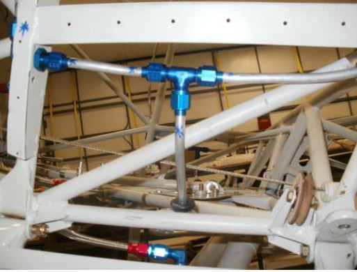
Larry's fuel line routing

Larry’s fuel line routing

Unfortunately life got in the way. My kids were finishing high school and I was on call most of the time. Tom got a sales job that took him away for most of the week. The project sat there for three years without any attention. I even put together a flier to sell the brand new Lycoming 390 engine we had purchased in late 2008. Then I acquired a partner and my call responsibilities were reduced. I had told so many people that I was building an airplane and I had had the dream in my head for so many years, I just didn’t want to give it up. I asked around the Hartford airport to see if there was anyone who might be willing to help me get started in earnest and guide me.
Fortunately, I met Marc Stamsta, a skilled craftsman who builds vintage wood airplane wings and spars for a living (www.maxaero.net) and he was willing to help me get the project going. I bought Tom’s share of the project and proceeded solo!
Marc met with me each Thursday and we tackled the wings first. I learned to squeeze and buck rivets and shape fuel and pitot lines. Despite having purchased the Wicks “hardware kit”, few of the bolts seemed to be the proper length and turnbuckles were not quite right half the time. This was one of the most frustrating aspects of the build. I had to hunt for the correct piece of hardware or thimble or cable. The “1,100 hour estimated build time” was quickly whizzing by.
15q3mHanging the wings met with near disaster when the drill bit became jammed at the root when drilling the hole to final size. Fortunately we were able to free it without damage. As with each part of the kit, we were impressed with the precision and quality of the kit. Everything seemed to fit together well.
It was on to the fuselage and I took on the fuel lines first. I made a slight modification in the route, and Bob indicated he saw no problem. Instead of bringing the rear line all the way forward of the doorframe, I routed the forward line back to meet the rear line below the door about even with the front of the seats. This allowed me to put the selector valve more aft next to the flap handle, the gascolator is aft of that and is more easily accessible behind the left landing gear.
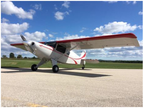
15q3nI chose to use a new fuel-injected Lycoming IO-390 EXP engine with 210 HP, and a Hartzell 80” constant speed prop. The hope was that it would provide an excellent balance of power and weight. I saved 100 pounds over the 540 and gained 30 HP over the 360. For the build itself, I’m thankful I went with the four cylinder as it provided a huge space between the engine and the firewall to fit things and route lines and cables. As a novice builder I think it would have been much more difficult with the 540. The one major disadvantage is that the #1 and #2 cylinder intake manifolds did not fit into the cowling, requiring modifications. Thus, the blisters on my cowl. I found some old Travel Air valve covers that worked very well. In retrospect, I probably would go with a standard 360 for simplicity.
15q3oI used a baffle kit purchased from Glasair, for use on their Sportsman model with the 390. Since my throttle body is horizontally mounted in front of the sump, the baffle kit goes down under the throttle body so that the entire area behind the nose bowl is pressurized. I have no alternate air or cowl flaps. My exit opening is less than the standard and although I put a lip on the opening, I’ve been trimming it back because even in 80 degree humid weather here in Wisconsin, my oil temps been 180-200 and CHT have been 325-350 max.
I used Vetterman’s crossover exhausts. Clint provided excellent sup-port, was easily available by phone and made some modifications at no charge until it was right. I needed to add their 4” extensions to direct the exhaust further down as it was really fouling my struts and underbelly without them. I have been told by others at HXF that the plane has a very distinctive (bad-ass!) sound.
15q3pFor the panel I chose the Dynon Skyview 10” monitor with their transponder, ADSB, engine monitoring system, GPS, heated pitot with AOA, and backup-battery. I took a seminar put on by Dynon at EAA prior to installing the system. I’m learning as I go and have had excellent support. Everything has worked as advertised. Rather than individual fuses for my electrical system I chose the Composite Designs Radio Stack power panel, which included the Master and Alt switches, Radio/Nav/Strobe/Fuel Pump/Landing Light switches and 14 breakers. It made the wiring so much easier and Wayne went above and beyond to give me some overall wiring advice. I used the ICom IC-A210 radio, and PS Engineering PM-1000 II four-channel intercom.
I enjoyed the wiring aspect of the build. I’m proud that I had only two issues, easily fixed with entire electrical system, despite completing it without any interim testing. The D-pins in the ADHRS connector cable were loose and had to be pushed in, and with the transponder and ADSB, I connected the TX to TX rather than TX to RX and had to reverse them.
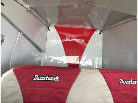
15q3qN460K is covered with the Polyfiber system. I also used it for my seat frame supports. I painted it in a paint booth at Tom’s hanger (where I was building) that he had used for a work-related project and allowed me to build out to fit the Bearhawk. I had hoped to have my three children participate in the build with me but you can lead a horse to water… My daughter Caroline did help by welding together two rotisseries for mounting the wings and fuselage for painting and covering. They worked beautifully. I could wheel the fuselage and wings into the booth and easily rotate them as needed.
I used PPG Aerospace Desothane topcoat and Desoprime epoxy primer. The EAP-12 Desogel non-chromate adhesion promoter was very easy to work with. Rather than using the toxic Alodine products, this just sprayed on with a spray bottle and then was dabbed with a cloth to cover the entire bare metal surface and was allowed to dry. No rinsing needed. The painting was laborious and since it was not perfect, frustrating. I learned as I went which isn’t the best plan when it’s the finished product! At one point there was a thin streak on the wing and I finally realized there was a strip of plastic still on the bare metal that I had not detected when scrubbing and prepping. I was able to fix it without any visible defect. The paint seems very tough and worked well on both the aluminum and fabric. I used the polyfiber silver UV-protector as the primer for the topcoat on the fabric.
My plane came in at 1387 pounds, achieving my goal of less than 1400. I can carry 400# in the front seats, 300# in the back seats, 165# of cargo and 50 gallons of fuel and still be at 22.5” aft CG.
15q3rN460K’s first flight was on May 16, by Tom Hegy, an experienced crop duster at HXF. No problems initially. I flew it a few days later and on my first landing the engine stalled as I was flaring. I had trouble re-starting and when it did start, the #4 cylinder was not firing. After about 10 hours of troubleshooting we determined that the flow divider was faulty. Precision Airmotive exchanged it for a new one and it has run smoothly since. I had taken transition training with Jared in February, which was critical for my confidence. Still I was anxious particularly about the ground handling and landing on pavement. Under the recent circulated FAA AC 90-116 (Additional Pilot Pro-gram for Phase I Flight Test) I was able to have several local instructors fly with me for the first 10 hours. By then I was getting comfortable and have put an additional 50 hours in so far. Going to Oshkosh and having N460K displayed at the Bearhawk Booth was a thrill and an honor.
Bicycles in the BearhawkWith regard to performance, I’m cruising at about 125 mph at 21” MP, 2300 RPM, consuming 8.5 gph. It seems the top cruising TAS is about 140 mph at 24 squared but at only 2500 ft MSL. I haven’t really taken it up higher and pushed it. I did take it to my 40th high school reunion in South Bend Indiana last month, taking the route under the O’Hare airspace along the Chicago Skyline over Lake Michigan, which was a thrill, especially since my wife came with me! I’m enjoying the process of learning the Dynon’s capabilities and with only a little over 100 hours of total flight time I have a lot to learn as a pilot. I look forward to the next 10 years with N460K.

Roy Glenn’s Bearhawk LSA

Source: 2014 Q4 Beartracks, Jared Yates
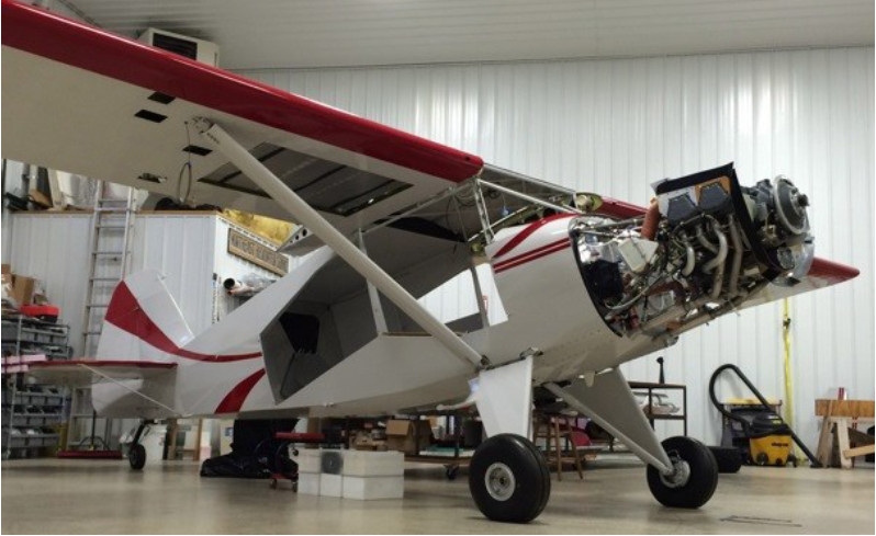
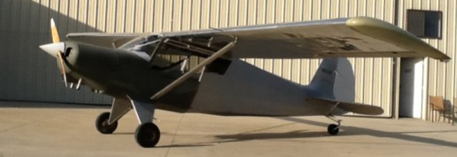
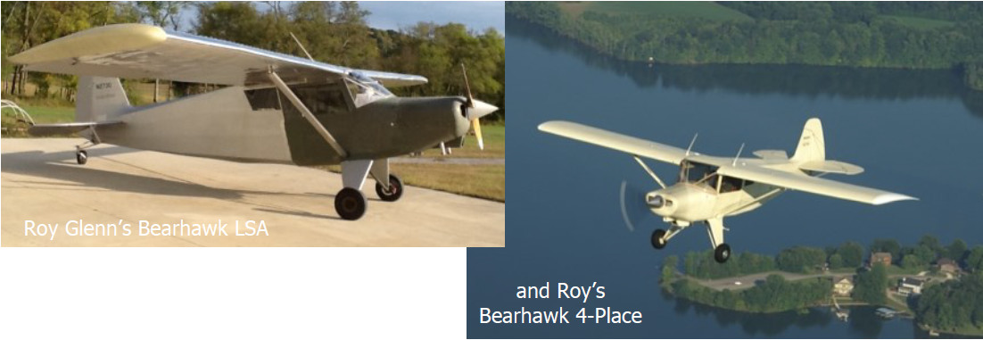
14q4mRoy Glenn is a frequent visitor to Bob’s fall fly-in. Over the years he saw Bob’s progress on the Bearhawk LSA prototype, and knew that he wanted to build one. After a few years of persistent expression
of interest, Roy was finally able to get Bob to sell him a set of plans for the Bearhawk LSA. 22 months
after Roy got the plans, Bearhawk LSA from plans number 002 was flying!
It’s fair to say that Roy’s building timeline is atypical, but then again, so is Roy. He is retired from a career that included simultaneously running a small construction business and owning a scrap yard, so he knows how things go together and come apart. He is also experienced with working on airplanes, having restored a 1941 Taylorcraft, a Cessna Cardinal, and having built a Bearhawk 4-Place from scratch.
Roy started his big Bearhawk back when he still lived in Connecticut, after reading the October 1995 Sport Aviation article that introduced so many people to the Bearhawk. In 1996 he saw the Bearhawk at Sun-N-Fun and was immediately sold on the design. As he says, “The Bearhawk, performance-wise, is hard to beat. I’m not going to find a better airplane for the type of flying that I do.” It took longer for Roy to finish building his first Bearhawk, in part because he had not yet retired from his two full-time jobs. Four years ago, he retired and moved to an airpark near Shelbyville, TN, 8TN2. He has dreamed of having such an ideal home and shop configuration for many years, and is glad to have finally been able to establish one. His hangar currently houses four airplanes: his Bearhawk LSA, Bearhawk 4-Place, Cessna 150, and project Corban Jr. Ace. The Jr. Ace was a donor to the Bearhawk LSA, contributing its Continental O-200 and wheels. The engine had just 175 hours when the airplane ended up on it’s back, damaging one of the wings, the vertical stabilizer, and rudder. 14q4l
Roy has been flying for almost 30 years, and especially appreciates the handling qualities of the Bearhawk LSA. The ground handling is a little bit more favorable than the 4-place. He has 56 hours on it so far, and hopes to fly it to Bob’s airport sometime next year. Roy’s Bearhawk LSA came in heavier than Bob’s Prototype at 890 pounds. Roy accounts for 90 of these pounds with options including a heavier metal prop, heavier McCauley wheels, starter, alternator, and battery. The covering process is Polyfiber, which Roy chose because he was familiar with it and has had good results in he past. He has not yet applied a top coat paint, mostly because he hasn’t been able to find just the right color yet. The paint on his 4-place has darkened with age, which has led to it being a shade of white that wasn’t his first choice. Roy reports that the building techniques were very similar for the two Bearhawk projects, with the exception of skinning the wings. Some of the skins on the LSA are .016 aluminum, which is very hard to work with because it is so delicate. He says that’s the one area where his cosmetic results didn’t turn out as well as he would have liked. Like many flying home-built airplanes, Roy’s LSA is still a work in progress. On his last trip to Airventure he picked up a GRT EFIS S200 and EIS 4000 engine monitor, and has been very happy with that change.
His next change will be to install a Lycoming O-235 that he is currently rebuilding, because he just likes Lycomings. He knew that this engine change was a possibility back when he built the fuselage, so he made the firewall two inches wider than the plans called for. The steel tube structure is built per the plans. After a few years of searching for a good deal on a core, he finally found one off of a Piper Colt down in South Georgia. He’s going to try to fit it in the first cowling, but concedes that he might have to build a new cowl. The Lycoming will certainly be heavier than the Continental, though he hopes to save weight with a lighter exhaust system and alternator, and he’s going to try to run without an oil cooler.
The long term plan is to put the Continental back onto the Ace. The Ace requires some structural repairs, having nosed over before he purchased it, but he looks forward to flying in the summer with the open cockpit. When I asked Roy what he plans to do with all of those airplanes, he says he intends to keep them all until he can’t fly them anymore. It’s clear that he enjoys projects, and is rarely without at least one in queue. As he puts it, “I’m a build-a-holic so I can’t resist building another one. I wouldn’t hesitate to do it again.” He says he has a set of Patrol plans on hand. Roy’s wife is very supportive of his airplane projects, though she doesn’t fly with him often. He says “She has her hobbies, I have mine, I guess that’s why we get along well.” We’ll definitely keep an eye on his progress, and follow up with an update on how he likes the new engine installation.

New Hot-Rod Bearhawk Patrol in Virginia

Source: 2014 Beartracks, Jared Yates
14q2oHatcher Ferguson and Don Aldridge have just completed their second Bearhawk Patrol, and it is a showcase of experience and ingenuity. The two built N22HD with performance in mind, and spared almost no expense. The fuselage is welded from a VR3 tubing kit, and the quick-build wings are from Bearhawk Aircraft. The engine started out as an ECI IO360, and now it flies as a fire-breathing 210HP example of “the best they could make it.”
Sky Dynamics of Moneta, Virginia modified the engine with a light-weight cold-air sump and induction system, lightweight flywheel, and 4-into-1 exhaust system. After the modifications Sky Dynamics ran the engine on their dyno to validate the performance gains. Two P-mags drive the electronic ignition system, and the fuel injection servo is from Don Rivera at Airflow Performance. Hatcher and Don Aldridge initially purchased a used Silverhawk fuel injection system on eBay, but the engine ran terribly with it. They took the servo down to Airflow Performance and found that it had been contaminated with water. Airflow Performance swapped out their servo for another, and now it runs beautifully. All of that power is turning an 80- inch carbon fiber Whirlwind prop, and Hatcher reports takeoff rolls consistently under 100 feet. Why did they install such a high performance engine? When I asked, the answer was along the lines of “to see if they could.”
Hatcher and Don know that the best way to further boost performance in an airplane with this type of hot-rod engine is to reduce weight. They considered weight savings in nearly every construction decision that they made. For example, they eliminated the skylight, rear seat throttle control and brakes, and the baggage door. They installed light-weight single puck brakes, used micro nutplates throughout, substituted #6 screws for #8 screws whenever possible, and minimized the size of welded tabs. The lightweight tailwheel assembly is Bob’s design, built by Eric at BHTailwheels.com. They redesigned the seats to reduce the width of the rear and increase the width of the front, and had a hot-rod shop shape the foam and sew the leather upholstery. The miniature Becker radio and transponder save a few pounds, as does the vacuum-pad alternator. The lithium battery saves approximately 15 pounds over a comparable Odyssey, but it still turns the engine over with plenty of gusto.14q2p
In some cases they added a little bit of weight to make the airplane more safe and functional. The LED lights and strobes give better inflight visibility to other airplanes, and allow for flights later into the evening when the flying is good. Hatcher says “they’re all LEDs, which hardly weigh or draw anything.” When that engine is running at full power and burning 17-18 gallons per hour, cooling is a concern. A cowl flap adds a little bit of weight but keeps temperatures normal. In the end, this airplane’s empty weight is 1168 pounds, 30 pounds lighter than their last.
A local expert helped fabricate a two-piece all fiberglass cowling. This doesn’t save any weight, but the new cowl is much easier to install and remove, and it has a more complex shape that reduces drag. The installed cowl is the third one made from the female mold. The first was two heavy, and they reduced the thickness of each of the next two. Hatcher speculates that they could save a few pounds by using carbon fiber instead of fiberglass, and fortunately they can use the same mold with carbon fiber to test that theory in the future.
What’s not to love about such an advanced flying machine? The paint, according to Don and Hatcher. Everything was going well as they applied the Polyfiber covering system to the powder-coated airframe. After they started painting top coats with the same Imron paint that they used on their blue Patrol, DuPont discontinued the product and they had to switch to the new “XL Pro.” The new product didn’t match the old product to their satisfaction, so they had to repaint several parts, at an estimated expense of 10-15 pounds. Hatcher says that he’s not satisfied with the way the paint turned out, but I’ve yet to meet an amateur airplane painter who will tell you he is. If the two fly it to Oshkosh next month as planned, I suspect that they won’t receive any complaints about it, especially if it is parked anywhere near mine!
The big question is, how does it fly? The specifics are still pending as they refine the calibration of their instruments. Hatcher reports that it handles just like their last Patrol, but has a much shorter takeoff, steeper climb, and faster cruise. They have only taken it on a few short trips, so they don’t have good cruise performance data yet. Hatcher says for local flights he uses about 13” MAP, 2300 RPM, and gets 100-110 miles per hour at 5.9 gallons per hour. If he runs the engine hard in level flight, his cruise speed begins to approach the realm of VNE, which is the main reason that their Patrol is a little bit slower than their RV10. Bob Barrows has flown the airplane and says that he likes the way it performs. Like most experimental airplanes, this new Patrol still has a few tweaks in the works. The static RPM is only around 2600, and Hatcher would like to gradually adjust it up to 2700. He would also like to fit a set of his giant wheel pants (for 6-8.50 tires) and build some fairings for the shock struts. I asked if they had kept track of how much they had spent on the project, and Don said “Yes, but we don’t discuss that!” with a laugh. Both are quite pleased with the way the airplane turned out, and I’m looking forward to seeing it in person!