Flight Testing Progress Report N907PM, plus Control Locks for the Flaps and Ailerons, Tail Lift

Source: 2024 Q3 Beartracks, Paul Minelga
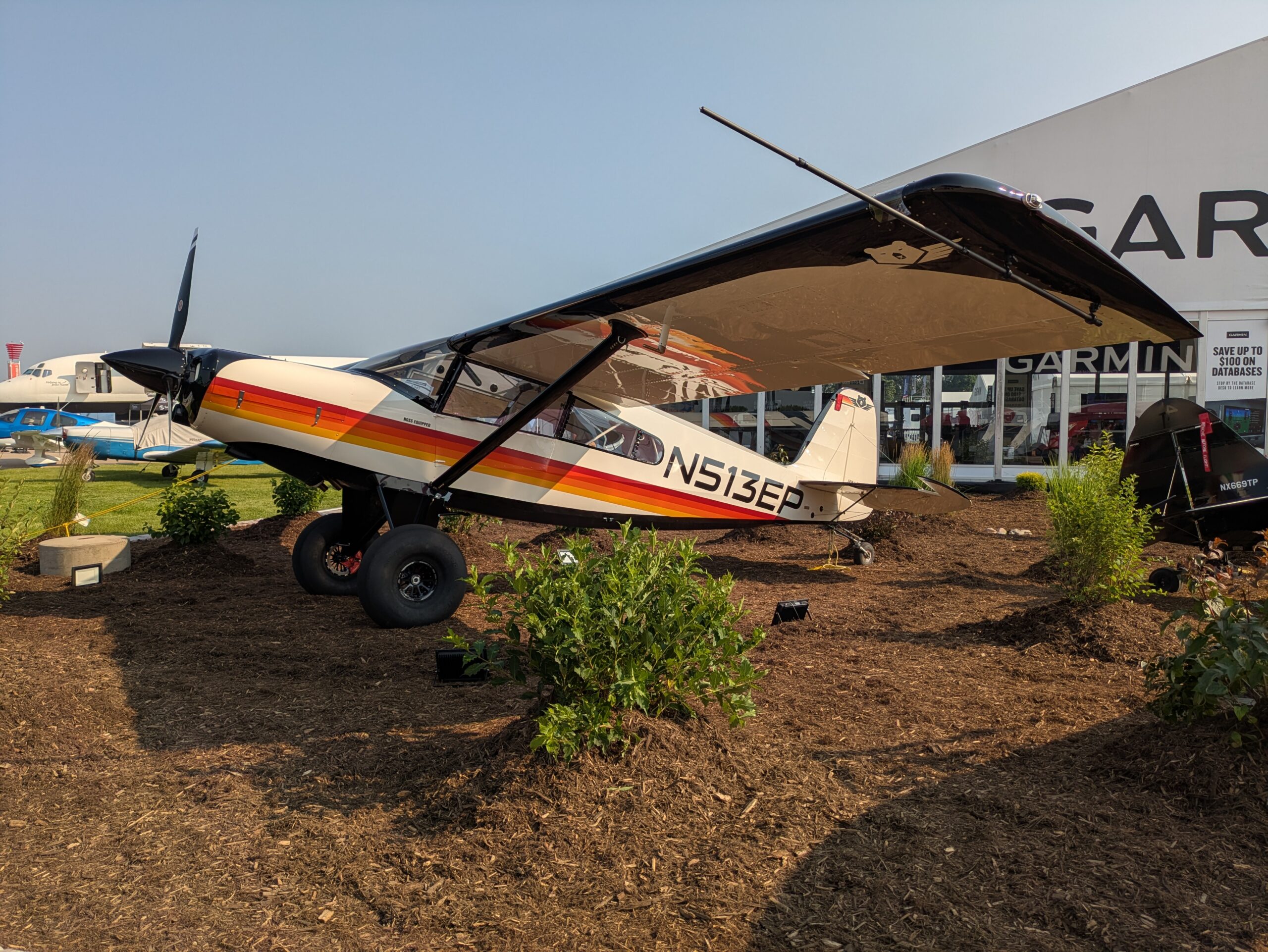
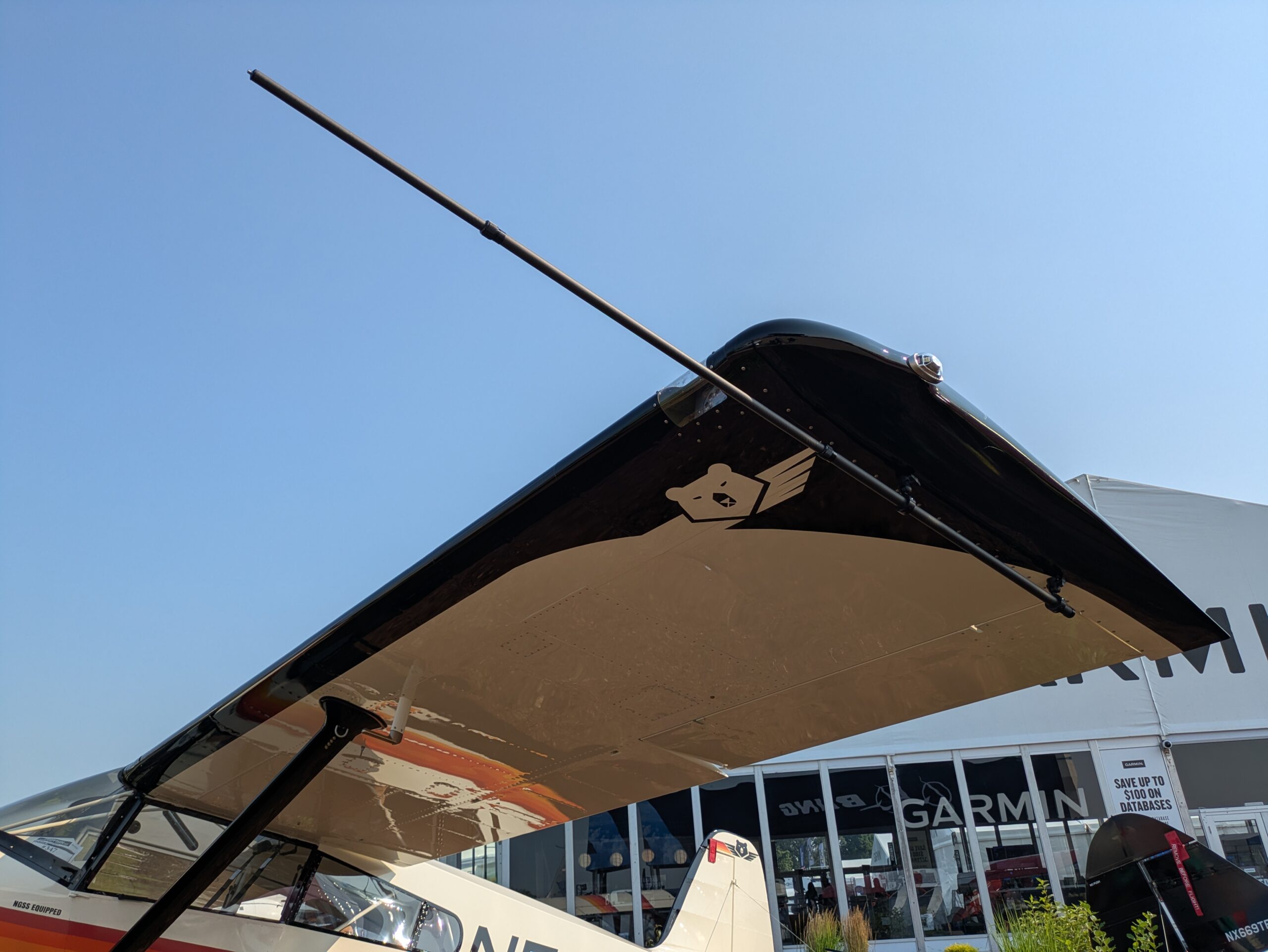
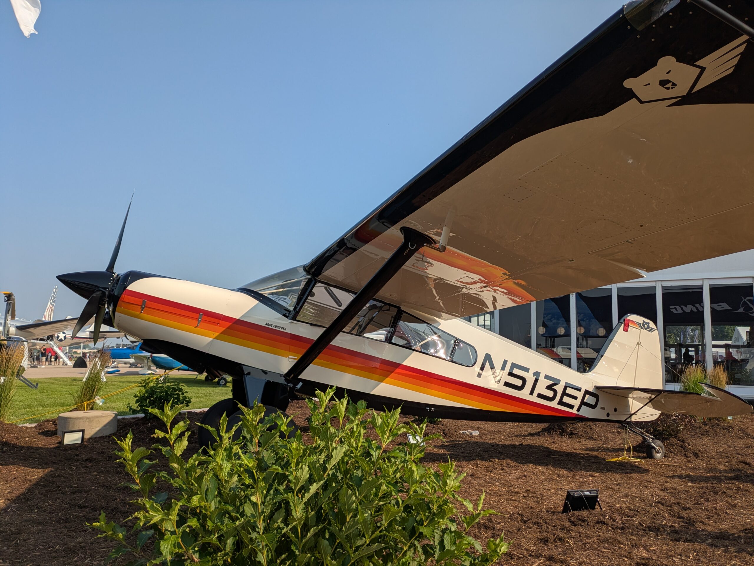
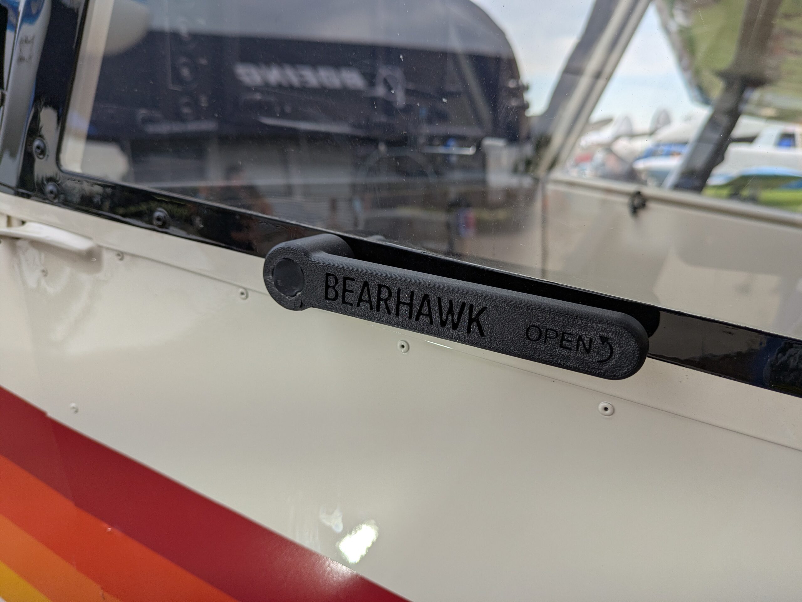
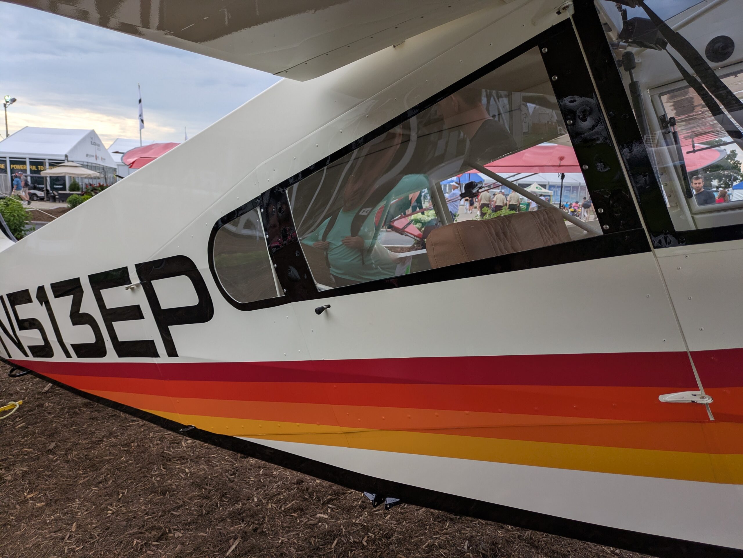
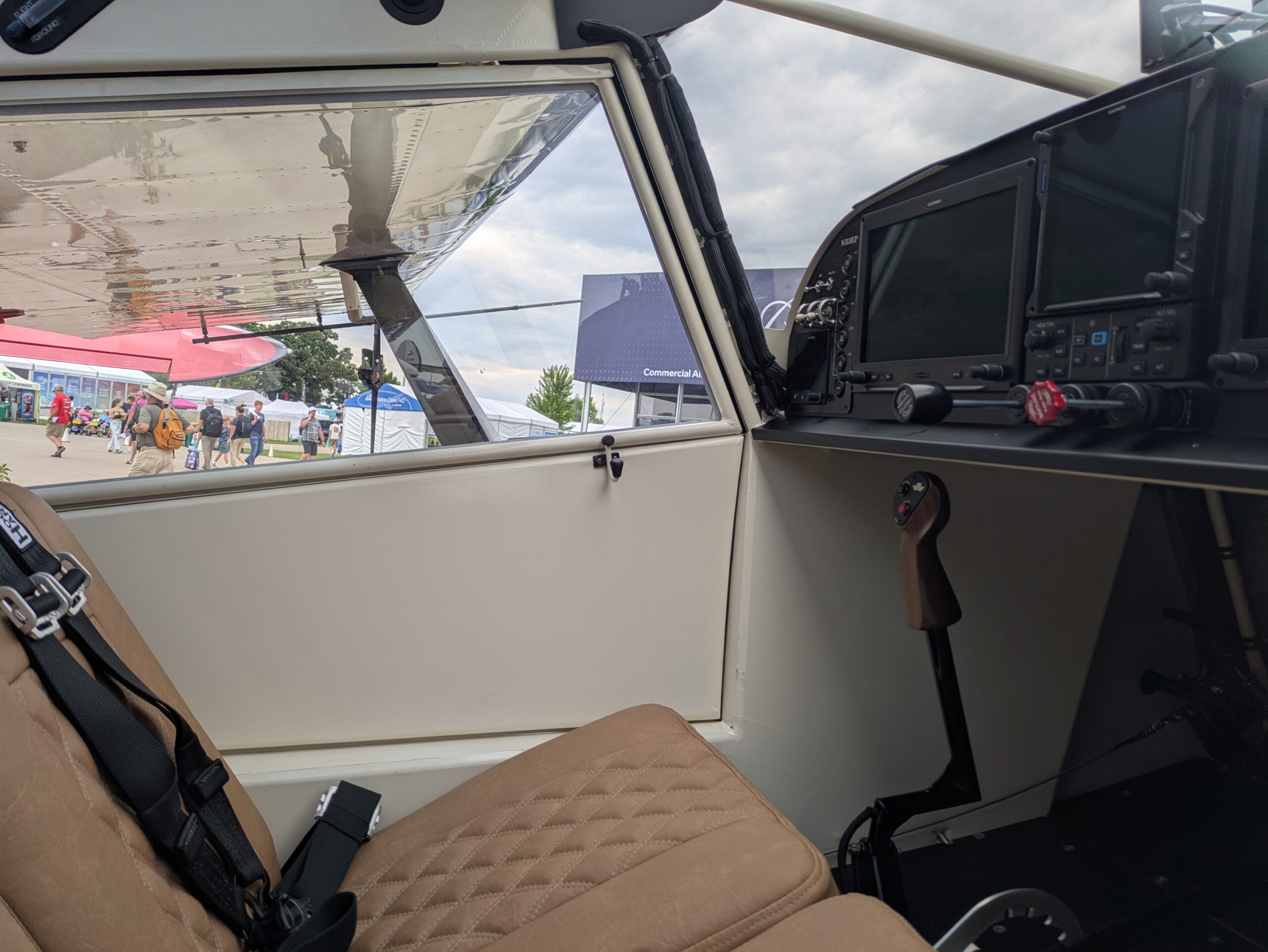
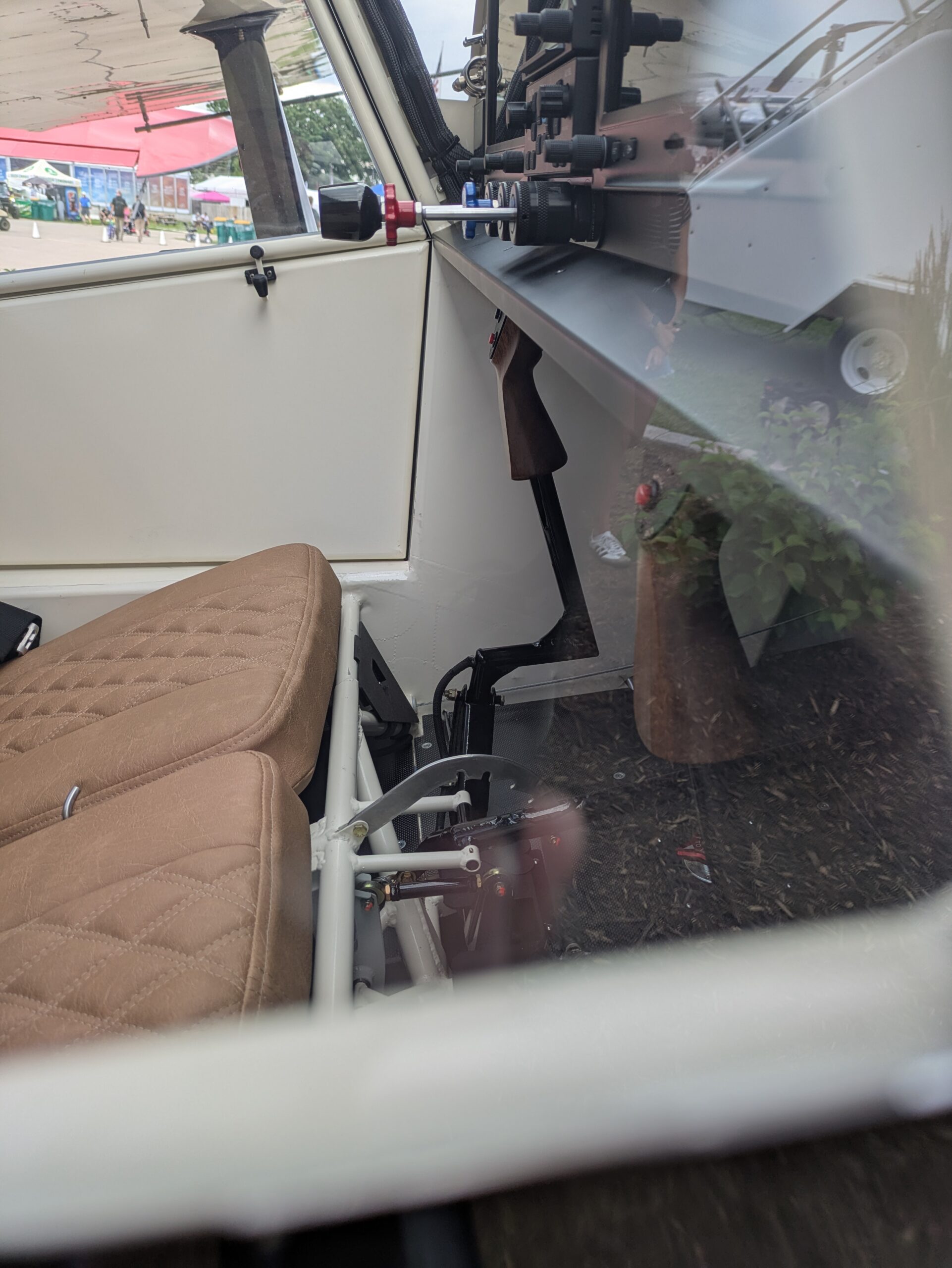
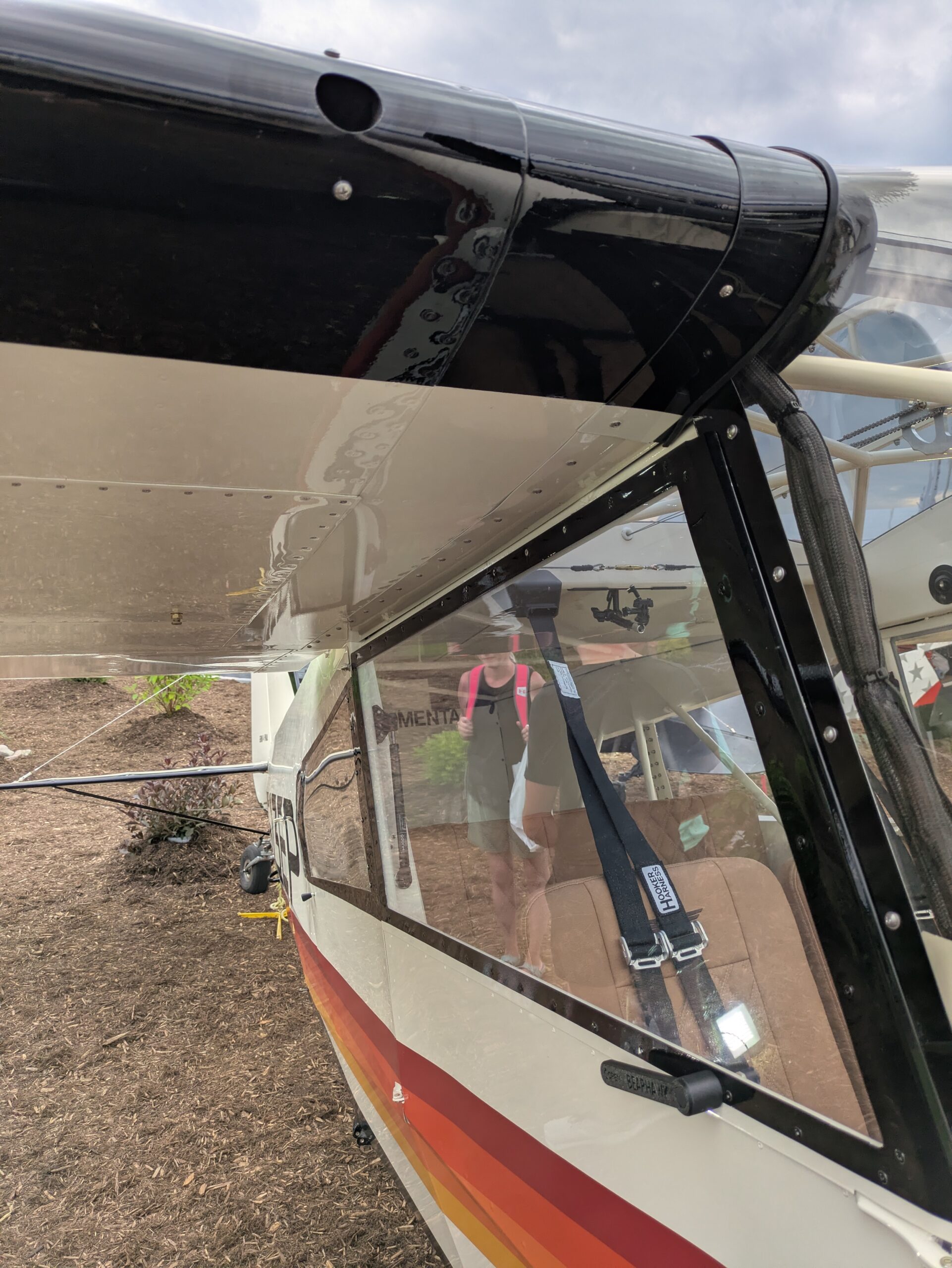
Here’s an update of N907PM’s flights, up to 28.2 hours on the Hobbs. Well, there isn’t much to update! This may be shocking to some, but completely logical to me, so let me walk through the hours from first flight to present.
I already went over my first flight in the previous Beartracks article and YouTube video, so no surprises there. So what happened next? Extensive testing of the flight envelope? Figuring out the handling characteristics of my Bearhawk? Multiple stalls, turns, simulated engine failure, full-flap landings? Nope. None of that…well, almost none, but I will explain why and you can critique as you wish.
The first flight was certainly an exhilarating experience. It was the first date with a new machine, flying at the upper range of its engine and airframe performance envelope. The excitement of not knowing which sounds were normal and which sounds could be the beginnings of a catastrophic event was to be experienced, as only one can on a first flight! Well, 1.3 hours later proved the airframe and engine were up to the task of at least one safe takeoff, flight and landing. But the question remained: What’s next? I have a considerable amount of time and money invested in the engine and I want to break it in as best as possible. The EAA test flight checklist doesn’t allow for this scenario. Since the aircraft didn’t offer up any surprises and it is a proven design, my focus on the subsequent hours were focused on engine operating parameters and a proper break-in. In other words, I ran the engine hard. Running hard meant no air work, no slow flight, no series of stop and go landings, no shock cooling, all in the name of engine break-in.
At 5 hours I did my first oil change, and it was necessary! The oil looked like metallic graphite paint! I cut apart the oil filter and thankfully it didn’t yield any unwelcome surprises. Along with the oil, the oil filter just showed minute evidence of a LOT of new moving parts in a powerful internal combustion engine getting to know one another. I even pulled the oil screen in the sump. Fortunately, there weren’t any pieces with part numbers trapped in its mesh. Oil was still being consumed, or blown overboard, but I still don’t know where this engine’s “happy spot” is on the dipstick…every engine has one. So more flying is in order….a lot of flying…within gliding distance of my home airport, until about 10 hours. After that, I did a flight with the last 30ish minutes using a modified EAA test flight checklist by doing stalls and exploring trim changes with different flap settings. I also did a full-power go-around at altitude with three notches of flaps to check if I could overcome the sudden initial trim change. I did.
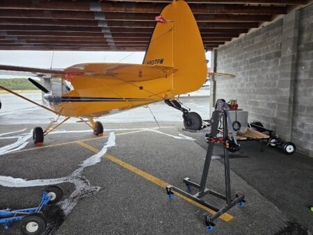
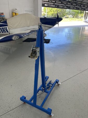
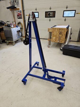
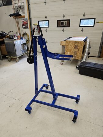
After that 10ish hours without an engine failure I figured it was time to spread my wings a bit and do a little cross country, at full power of course. I was flying in familiar territory. In my beautiful part of Alaska there are a BUNCH of airstrips available in case of an unfortunate event. Almost all are private, but I have yet to meet anyone that would not welcome a pilot in immediate need of a short, semi-flat surface. So my next 15 hours were spent doing cross country flights, at altitude, at close to full power. At 25.4 hours it was time for a another oil change and a good look over of the airframe. In addition to the oil change, I did a mini condition inspection as most of the important parts on the airframe and controls are hidden behind panels and can’t be seen on a preflight. I built a tail stand and calibrated my oil dipstick in the 3pt attitude and verified the factory stamped level attitude markings.
So what are my takeaways and what did I learn? First and foremost I always did a good preflight and a very thorough post-flight after every flight. On one post-flight I discovered the inlet fitting of the oil cooler started leaking. Everything stopped until it was fixed. I also maintained a meticulous log of the engine parameters. Even at the top end of the performance envelope, flying in circles can get pretty boring. Every flight I recorded the OAT, engine oil temperature, oil pressure, each cylinders EGT and CHT (Number 2 has always been my hottest), fuel flow, volts and amps. During my cross country flights I experimented with how minor trim settings affected level flight and always tried to keep my altitude within 50 feet of my target altitude. BTW, my BH can be trimmed to fly hands-off in smooth air, no heavy right wing as some have experienced. I feel very fortunate in that area. I also have a real-time CO detector in the cockpit and I recorded those readings as well. I never saw more than 1 PPM in level flight and 8 PPM maneuvering. I also took note of the differential between the level of the fuel tanks after refueling. I always flew with both tanks selected and never had more than 1 ½ gallons differential between the two at refueling.
One thing that took me off-guard a bit was making the transition from fabrication mode to maintenance mode. I built this thing, now I have to maintain it. It’s a completely different set of skills! I started a list of deferred maintenance items to “fix” during my next condition inspection. They are all minor, but should be resolved.
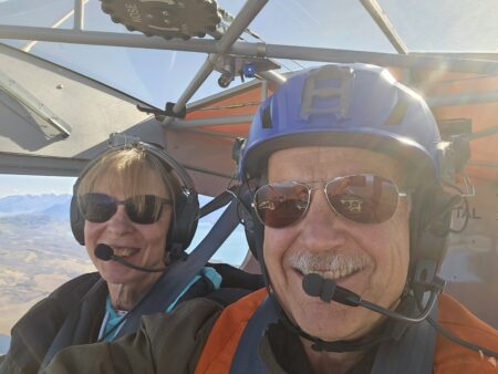
Now that I am satisfied that the engine is broken in and the aircraft doesn’t exhibit any control anomalies, I will start and complete the EAA flight test checklist. I feel it is very important to do the methodical testing and documentation of the aircraft. But, like I said before, this is a tried and true design and the first few hours didn’t exhibit any builder-induced surprises, so I was comfortable in getting the engine properly broken in before going any further. As an aside, I legally took up my first passenger the other day…my wife! The day was stunning. It was completely clear, light wind and the fall colors of the birch and aspen against the turquois blue of the Kenai River were amazing. Even Denali (formerly Mt. McKinley) was in full view in spite of it being over 150 miles away. “Don’t give in, don’t give up.” – Iwai Makoto

Control Locks:
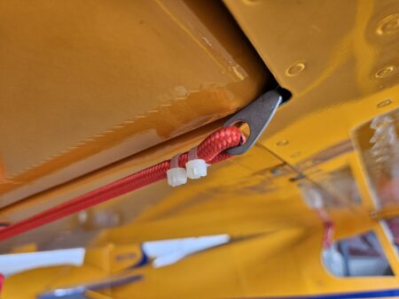
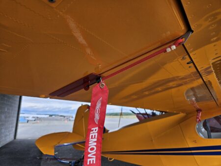
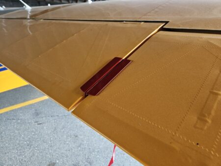
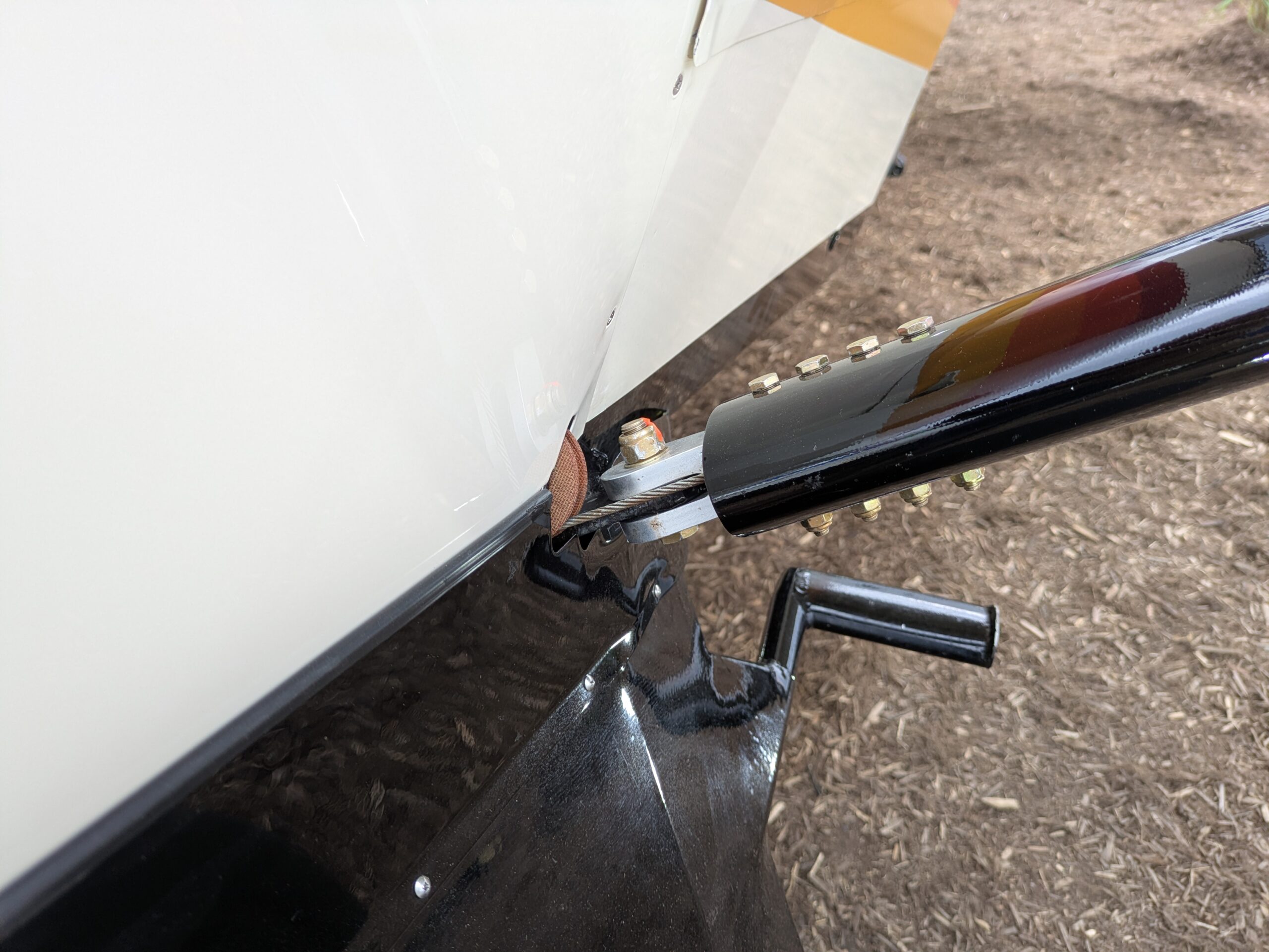
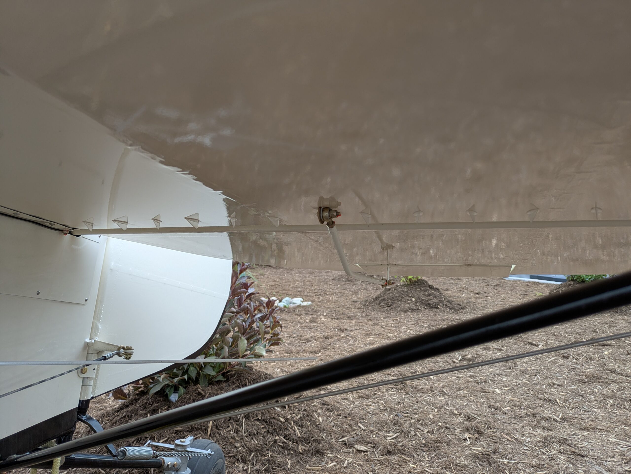
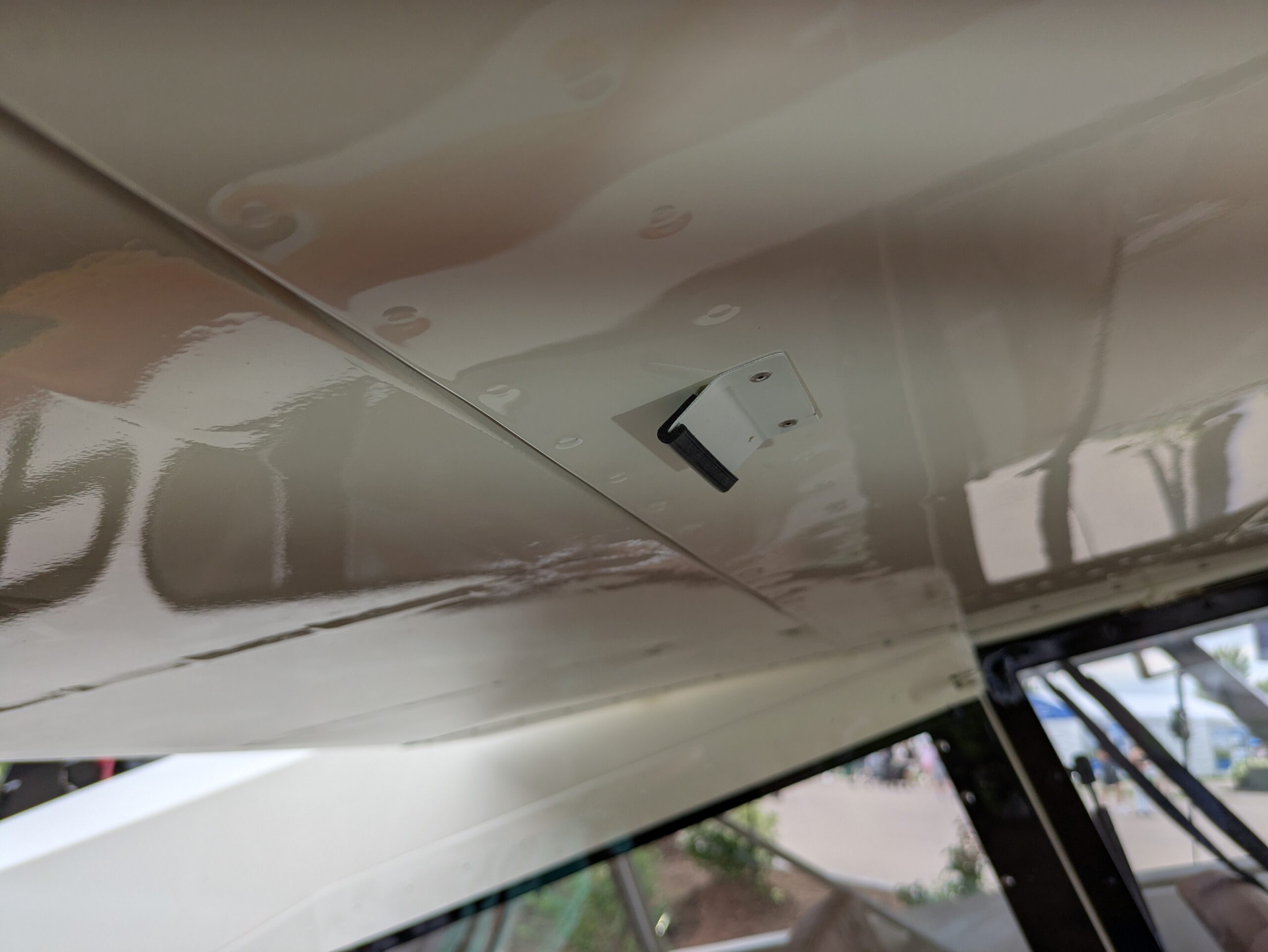
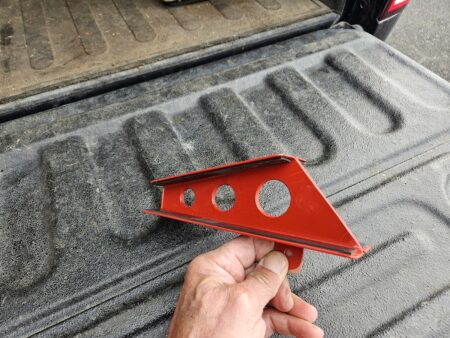
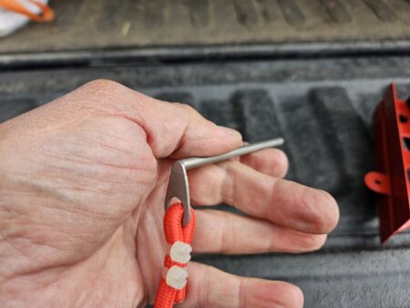
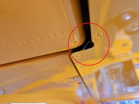
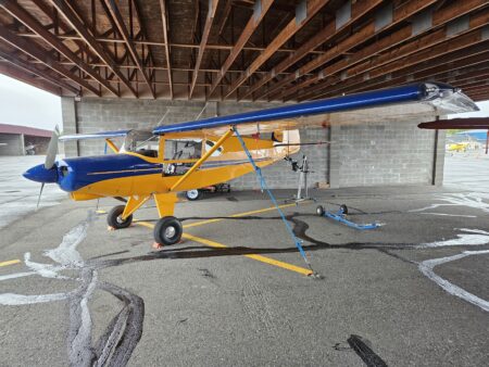
I want to share what I made for the 4-place BH. Yes, they look almost identical to the Atlee Dodge gust locks because that’s where I got the idea from. I would have bought them from Atlee, but I wasn’t sure if the profile angle of the Piper aileron/flap matched the angle of the BH control surfaces. Also, the bungees holding the Atlee locks in place wrap around the lift strut of the Piper. That isn’t an option for the BH as the lift strut is way out of alignment with the aileron/flap intersection. I looked at ways to attach a bungee and almost settled on drilling a hole in the bottom of the wing somewhere close to the edge and installing a small eye bolt. I spent a lot of time just thinking about options when saw a little hole in the wing that is created by a stiffener that is riveted to the trailing edge of the flap pocket. I tried out different diameters and lengths of rods and found one that slid in and out without any trouble.
I made the pins and the eyes welded to the end of the pins out of stainless steel so they wouldn’t rust. I made the locks themselves out of some scrap .060 5052 that I had in my now vacant shop and glued some neoprene strips on the surfaces that contact the fabric. A couple of red bungees, flagging and some zip ties later I have a set of gust locks!
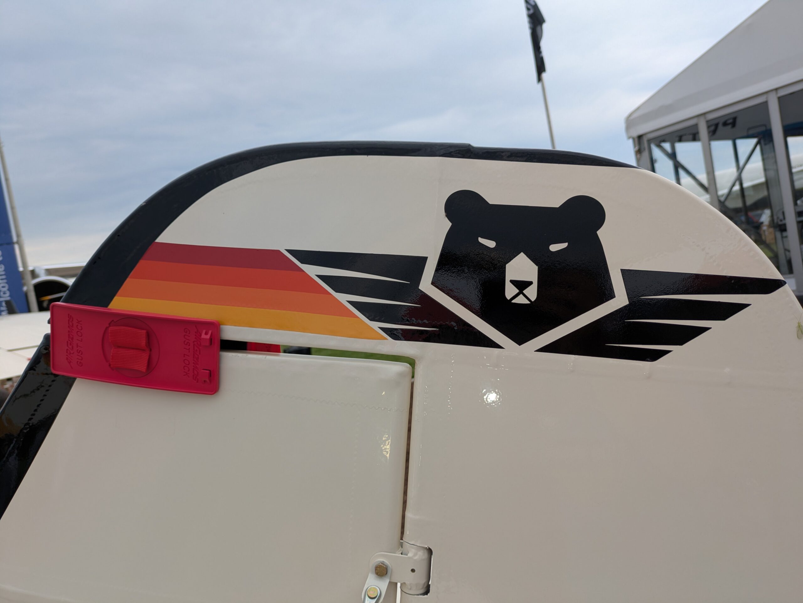
I have a set of Air Gizmos gust locks that I was using for the flaps, but I had to still tie the stick back. Also, there were a couple of times I found the gust lock on the ground when it had worked itself loose. The Air Gizmo lock works great as long as the surfaces are close to parallel. So instead of buying another set for the elevator, I made these and am now using the ones I had for the flaps on the elevator. Now everything is tight and I don’t have to use the seat belt to tie the stick back.
Tail Lift:
Elevator Trim Torque Tube Ends on Factory Kits

Source: 2022 Q2 Beartracks, Mark Goldberg
Over the years we have seen some cases where the trim “arms” in the horizontal stabs get play in them where they are bolted to the 1/2″ x .035 tube that runs inboard through the horizontal stabs to the trim horns in the fuselage tail. The plans show that arm welded to the 1/2″ tube, but we have always sent the kits out calling for an AN3 bolt to connect the parts. If they are welded – the mechanism can never be removed from the horizontal stabs. That was our motivation for doing something different than the plans show. Bob was aware of this and did
not have a problem with the different way of attaching those parts. The actual stress on the parts is not great. However, vibration in the tail surfaces causes problems as we have seen over the years in other areas.
So there is a new recommendation from Bob on how to connect those parts together. Before the final assembly, clean the parts so they are not oily. Then as you insert the 1/2″ tube into the 5/8″ tube of the “arm”, apply red Loctite. Then go ahead and insert the AN3 bolt. The red Loctite should eliminate any chattering from vibration. Interestingly – the trim horns are attached to these same 1/2″ x .035 tubes with AN3 bolts. There has never been a problem with those parts getting play in them. Just out in the horizontal stabs. Please check this area when you inspect your planes. If something needs to be done – you can install an inspection ring in the fabric there to permanently allow access. Continue reading

Rudder Cable Attachment Detail for Tandem Seating

Patrol builder Stefan Hechenberger made this fantastic detailed diagram of how the rudder cables attach to the rudder pedals.

The BOM for one side is:
Front rudder pedal
1x AN3-13 bolt
1x AN393-13 clevis pin
1x AN960-10 washer
2x AN960-10L thin washer
1x short bushing
1x long bushing
2x cable link
1x AN310-3 castle nut
2x MS24665-151 cotter pin
Connection front to rear pedal
42″ of 1/8″, 7×19 galvanized cable
2x AN100-C4 cable thimble
2x MS51844-44 nicopress sleeve. 1/8″
Rear rudder pedal
1x AN3-13 bolt
2x AN393-13 clevis pin
1x AN960-10 washer
3x AN960-10L thin washer
1x short bushing
2x long bushing
2x cable link
1x AN310-3 castle nut
3x MS24665-151 cotter pin
Connection Rear pedal to rudder horn
turnbuckle (clip version)
1x MS21251-B5S turnbuckle barrel
1x MS21255-5RS right turnbuckle eye
1x MS21255-5LS left turnbuckle eye
2x MS21256-1 locking clips
190″ of 1/8″, 7×19 galvanized cable
4x AN100-C4 cable thimble
4x MS51844-44 nicopress sleeve. 1/8″
Rudder horn
1x AN115-21 shackle
1x AN393-13 clevis pin
1x AN960-10 washer
1x MS24665-151 cotter pin

Some notes about assembly:
I made sure the cable links rotate freely on the bushings. I reduced the diameter slightly and adjusted the length to just prevent the bolt from squeezing the links.
The rudder horn is slightly thicker than the shackle allows. Slightly bending the shackle open is necessary.

Bob prefers to not run turnbuckles in the rudder system, because the rudder system is an open loop that doesn’t need to be tensioned. If you are not using turnbuckles, make the cables one piece from the rear seat rudder pedals back to the horn. If you do add turnbuckles, they are best positioned aft of the baggage area.

Spring Bias Rudder Trim

Source: 2021 Q3 Beartracks, Mark Richardson
I am currently scratch building a 4 place A model Bearhawk and I am always looking for both cool ideas and “things to avoid” during my build and am trying to incorporate those that will prove to be handy but not compromise the engineering of the design nor add significant weight. One idea came from my Maule M5-235C that I am flying until the Bearhawk is done.
I have found the rudder trim in my Maule (such as it is) to be really useful, especially on long climbs. However, depending upon speed I have had to fiddle with the setting to get things where I’m actually flying straight. If you aren’t familiar with the Maule rudder trim, it is essentially a handle you tug on that just pulls on your right rudder pedal with a spring. Dead simple. Also, right rudder trim only.
Since I am putting an electric elevator trim in my 4 place (actually, a G3X system with Autopilot and Yaw Damper), I had the elevator trim wheel left over. Also, since I really don’t want to have an ugly rudder trim tab sticking out the back of the airplane, nor do I want to be trimmed for only one speed (unless I have built everything perfectly straight…not likely since this is a scratch build) I thought I would try and design and build a rudder trim system that is completely adjustable.
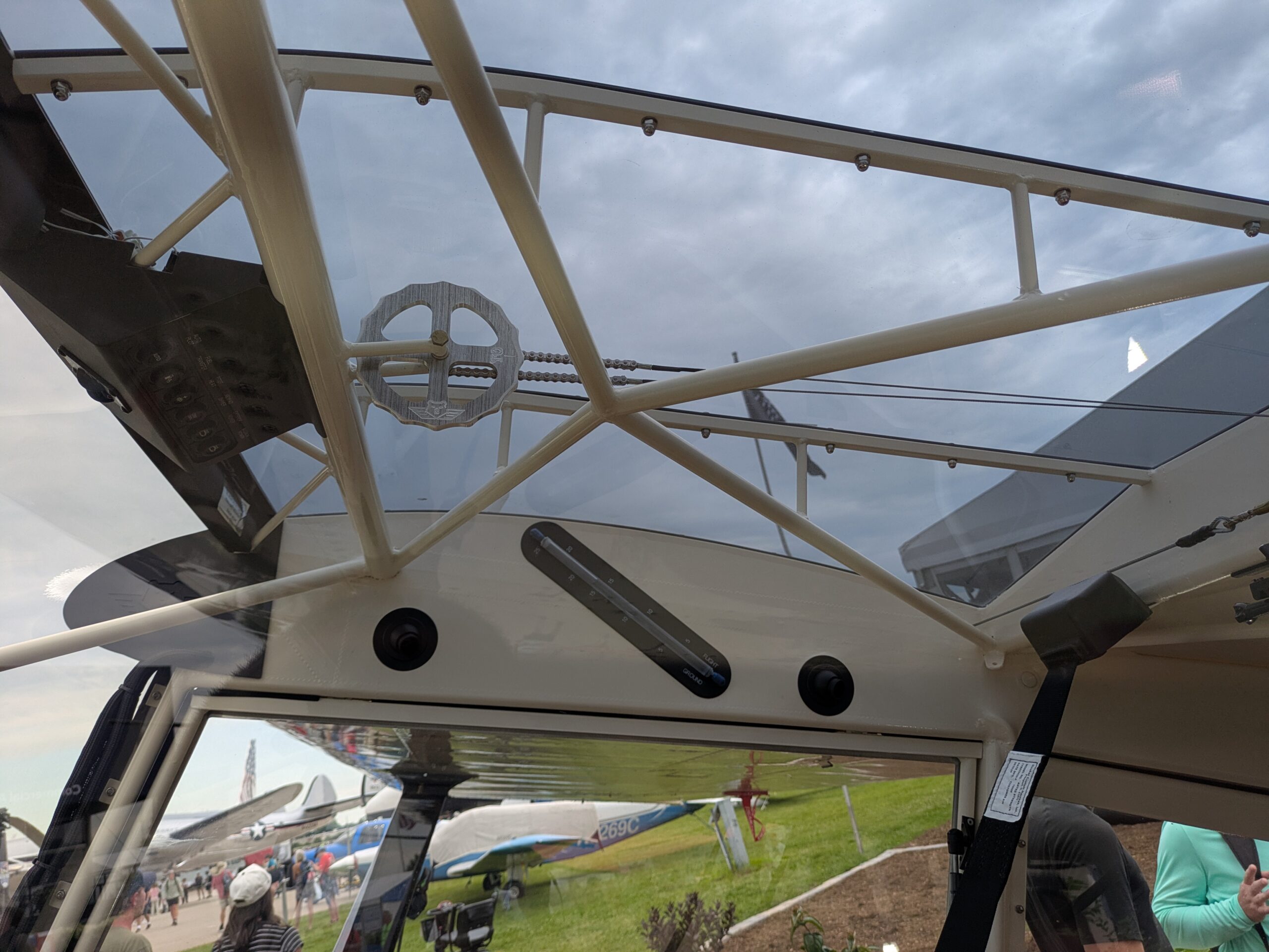
The rudder pedals on the Bearhawk require return springs so they don’t fall over onto the floor when your feet aren’t on them so I figured I would use those springs as part of the rudder trim (like the Maule, but for both directions). The elevator trim wheel has a sprocket and comes with a chain, so if I could manage to mount the wheel in an unobtrusive place but still have easy access to it, that would be ideal.

The photo above you can see where I just welded on an .063 4130 tab directly underneath the throttle quadrant (which is a welded plate so that I can remove the panel without removing the throttle/pitch/mixture). The friction of the wheel will be set by a magical combination of washers, castle nut position, and just the right amount of tongue sticking out as I tighten the whole thing up and install a cotter pin.

This is the view from the panel side. Very easy to access and not too unsightly.
The trim wheel is attached to the rudder pedals through the rudder return springs, which in turn are connected through some 1/16” galvanized cable, pulleys, and shackles. There are two 1.75” pulleys for each side and they are oriented to run the 1/16” cable down the tube to a point just forward of the rudder pedal return spring arms.


This picture above shows the connection to the rudder pedals themselves. This was the biggest issue when I was designing how the system would work. Originally, I had the pulley farther down the tube and the shackle was on the return spring arm itself. The problem was that the thimble and swage now interfered with the pulley. A friend suggested an offset connection of some kind, so I made the 4130 plates you see here and used a long bolt with the shackle to make the connection.
The system seems to work quite well but I will only know for sure once the aircraft is flying … which be Tuesday … I’m just not which WHICH Tuesday…

Using Clip-Lock Turnbuckles

Source: 2020 Q3 Beartracks, Rob Caldwell
Turnbuckle Conversion Table
Builder Rob Caldwell has been making fast progress on his Bearhawk 4-Place. He’s installing MS Clip Lock turnbuckles instead of the older style AN turnbuckles that are secured with safety wire. This table shows the part number conversions for folks who might like to do the
same. The center column shows the traditional safety wire turnbuckle parts, and the right column shows the MS Clip-Locking style.

Type Safety Wire Clip Lock
Outer Ailerons (AN130-32L) 2 ea.
Barrel AN155 MS21251-B5L
Fork Eye AN161 MS21252-5LS
Cable Eye AN170 MS21255-5RS
Cabin Center Aileron (AN130-16S) 1 ea.
Barrel AN155 MS21251-B5S
Cable Eye AN170 MS21255-5RS
Cable Eye AN170 MS21255-5LS
Flaps (AN130-16S) 2 ea. (same as outer ailerons)
Barrel AN155 MS21251-B5L
Fork Eye AN161 MS21252-5LS
Cable Eye AN170 MS21255-5RS
Elevator (AN135-32S) 2 ea.
Barrel AN155 MS21251-B5S
Pin Eye AN165 MS21254-5RS
Pin Eye AN170 MS21255-5LS

Service Notification for Patrol and LSA Kit Tail Struts

Bearhawk Aircraft Service Notification June 16, 2020 – For questions call Mark Goldberg, 512-626-7886 The horizontal stab strut for the Patrol and LSA share a common design feature on the top – how they are attached to the leading edge tube of the horizontal stab. An AN5 bolt has its head removed, and it is heated and forged flat with the 3/16” hole drilled for attaching to the horizontal stab with an AN3 bolt. The factory also cuts some more threads to add additional adjustment length. Some of these parts have left the factory improperly forged. The forged part (where the 3/16” hole is) needs to be flat so it fits flat against the bottom of the horizontal stab tube and also have the nut on the bottom fit flat. The parts not forged properly have an angle to them and are not flat on both sides. This can put stress on the AN3 bolt. There are two ways to fix this part if you have one or two that are not forged flat. One side can be ground down flat on a bench grinder if the remaining material is at least 1/8” thick. Of course any roughness or marks from the grinding would need to be polished/sanded out. Bob Barrows does a different fix for a situation like this that requires welding. A washer is tack welded to the “fatter” side of this part where the attach hole is. Then the other side of this washer is adjusted so it is flat compared to the other side. Then finish welded in place. Please inspect these parts that came with your Patrol or LSA kit. If they have this problem you should try to make the “repair” as detailed above. If you are unhappy with the result for any reason, let us know and we will replace these for you.
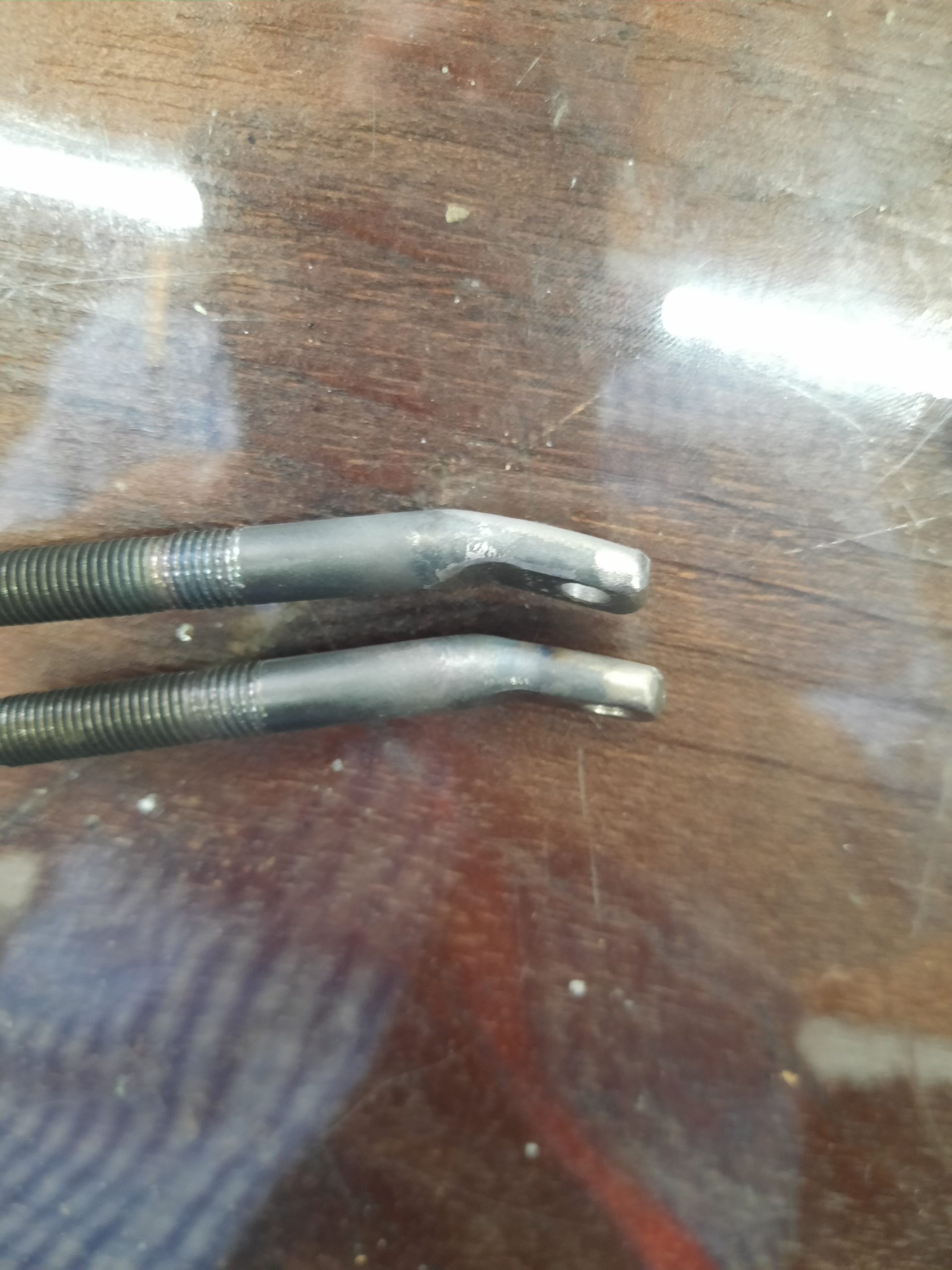
Horizontal Stabilizer Struts, Female 5/16″ Threads

A Tale of Two Tail Struts
Source: 2019 Q1 Beartracks, Jared Yates
It was the best of times, it was the worst of times. We had some visitors in town that wanted to go for an airplane ride, so we drove out to the airport and started the usual preparations. Bearhawk folks have known for some time that the airfoil-shaped front support struts for the horizontal stabilizer are a candidate for extra preflight scrutiny. As usual, in my preflight walkaround I grabbed the strut and gave it a tug, but not as usual, the bottom end came off in my hand. The friends were understanding about not getting to go for a ride, or at least they said they were, so I removed the upper bolt still holding the strut on, and went back home.


When the guests were gone I was able to study the broken AN490, which you can see above. This cross section shows that a crack had been developing across the part for some time, with the dull gray part being the section that was holding together at the time of my inspection. Would it have been safe to fly if I had neglected to break it? Probably so. It is said that Bob flew the prototype Bearhawk without the struts before adding them later in testing. It probably would not have broken yet, but it was going to happen sooner or later. At least this was a time of minimal inconvenience.
A few years ago I had contemplated stripping the covering off of the horizontal stabilizer to add wooden strips and give the ribs an airfoil cross section, also adding provisions for an electric trim servo. That project never made it to the top of the to-do list, but since that mod leads to a reduction in the incidence angle, it also requires longer tail struts. This meant I had a pair of spare AN490s on hand, so my plan to fix this was to weld a new one in place of the broken one and carry on.
But as things tend to go, fixing one thing seldom means merely fixing one thing. In recent years we noticed that in cruise flight, the elevator was displaced in a stick-forward position from neutral, based on looking out the window at the counterbalance. This meant we needed less incidence already, even without switching to the profiled rib shapes. If we were going to be making new tail struts, we might as well account for this. I mentioned the part failure to Bob on the phone, and he had some input. First, he reminded me that the tail strut we were using didn’t match his original design. The original does not allow for any adjustment, it’s just made in place to fit. In the early days of the factory, the tail struts were made with welded-in AN490s, which paired with the AN665 female-threaded clevis. The thread size is 1/4×28. One of the problems with this arrangement is that in the welding process, the protective cad plating layer is burned off of the AN490. Threads are extreme stress risers, and this combined with inadequate corrosion protection is not a recipe for success.
Bob had several ideas for an improvement, and here are the two that I liked the best. First, he suggested welding a tube onto the end of the strut, cutting female threads into that tube, and swapping the AN665 out for a clevis with male threads. He also suggested considering a 5/16” thread size, which would be much more durable. With this arrangement, the exposed threads would still have their protective plating, and the cross section area of the clevis inside the threaded area would be much larger.
The first step was to have the parts manager get to work sourcing the supplies, starting with a male threaded clevis with 5/16×24 threads. I couldn’t find one in the aviation catalog, but McMaster Carr carries one as part number 4749T11, $6.05 each. Next we needed a foot of 4130 tubing, 7/16x.095. A few inches would have been fine too, but there wasn’t any in the scrap pile and the minimum order is a foot. The tap and drill were already on hand.
Before starting, I measured the original strut length (36-5/8) to make it easier to guess the new length. Next I cut out the old AN490 with my new portable bandsaw mounted in its Swag Offroad benchtop table (thanks for the tip, Rob Caldwell), and was surprised to find water running out of the tube. The bottom end of the strut is sealed, but apparently it was possible for water to run down the leading edge of the horizontal stabilizer, then between the stabilizer and the strut, then between the layers of the smashed strut end. This would motivate me to weld closed, then re-drill the strut top hole, sealing the struts against future leaking.


Once the slots were cut, I drilled just outboard of the end of the AN490, which liberated the old fitting.

A rotary file made easy work of smoothing the remains. The 7/16 tube fit nicely in that slot, needing only prep for welding, and trimming to length once the welding was done.

Cutting the threads into the tube was a slow process of back and forth every quarter turn. If I had any doubts about how much work the tap was doing, the hot temperature of the tube reminded me.

Next, I needed to reduce the incidence angle by shortening the spacers in the horizontal stabilizer mounting structure. Rather than shorten the old spacers, I made new ones at half length. A folded wire tie held them nicely for painting. In the final installation, I installed a jam nut to keep tension on the threads of the clevis, and I ended up shortening the 7/16 tube by about an inch compared to the image above. In retrospect I should have shortened it before cutting the threads, since that would have saved half an hour of tapping. The end result seems very durable, and initial flight tests after the adjustment suggest that if anything, it may not be enough correction, but at least it is a step in the right direction. I’ll need to fly with a heavier load and further aft CG to see where the elevator falls, but it is currently in trail with the stabilizer at casual local flying weights.
A little more room here would have been helpful. Original spacers are 1/2″

Original spacer

New Spacers Cut

Wire tie holds the new spacers for paint

Bearhawk 4-Place Trim Tab Experiment, Lengthening the Horn

Source: 2019 Q1 Beartracks, Tim Babcock
Editors note: Readers may remember Tim’s Bearhawk, modified with control yokes instead of sticks. Even though parts of his pitch system are different, there is useful information here about the geometry of the elevator on the Bearhawk 4-Place. Take note of the recent safety update related to elevator trim cable tension, Bob wonders if this could have been a factor in Tim’s case also.
I was trying to come up with a simple fix for the pitch sensitivity on my Bearhawk 4-Place. Up elevator isn’t bad but down throws you up into your seat belt in turbulent air. Once it is trimmed up and appears to be flying along nice and level and you give the stick a little nudge and let it go it will diverge into these big oscillations and you have to take it back. It will not revert back to trimmed flight on its own. I wanted to keep the servo trim tabs because they are nice for long flights and flying heavy. Nice and light on the controls.
First I started using an electronic level to measure elevator travel and trim tab deflection a degree at a time. But soon discovered that it wouldn’t work because the tab is moving along with the elevator. And in the case of the elevator moving up from neutral, the tab trims down normally for only 7 degrees and then the tab stops trimming down and and just rises with the elevator and the tab degrees rise up instead of down. So the protractor was better.
I devised an extension arm that bolts through the original tab lever holes. With the tab lever sandwiched between the longer lever and a dummy lever on one side. The tops of the longer lever and the dummy lever are bent over 90 degrees about 3/8″ wide so when clamped in place the bent over ends can press up on the bottom of the trim tab front tubing for support, to prevent side wobble and then break off the tab. The tab lever was at first 1.8″ longer, from the tube centerline to second hole from the bottom.
The following are measurements of the elevator trim tab and elevator degrees of travel using a protractor, for both the standard trim tab and a modified lengthened lever.
Standard trim tab lever:
Down elevator – 21.3 degrees
Elevator trim tab deflection – 31 degrees up (Compounding Servo)
Up elevator – 29.0 degrees
Elevator trim tab – 12 degrees down
Modified trim tab lever:
Down elevator 21.3 degrees
Elevator trim tab deflection – 15 degrees up (almost balanced with up servo)
Up elevator – 29.0 degrees
Elevator trim tab deflection – 10 degrees down
In normal level flight the tabs barely deflect with average corrections. Before, the down elevator was being trimmed by the tab, which was moving 10 degrees more than the amount the elevator was being deflected.
I have sold my Bear-hawk now due to some health issues. The new owner has moved the trim linkage to the long-est hole now further reducing the up travel of the trim tab, and has no more sensitive trim. Acts in a true fashion and good feedback to the control yokes. Very stable in flight now. The flight instructor who I checked out and who spent 10 hours checking out the new owner said it’s a dreamboat to fly.