Seat Upholstery by Sport Aircraft Seats

Source: 2021 Q3 Beartracks
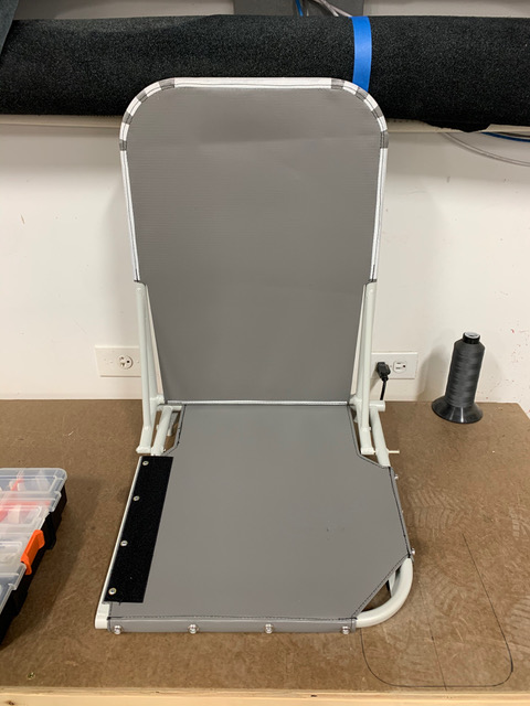
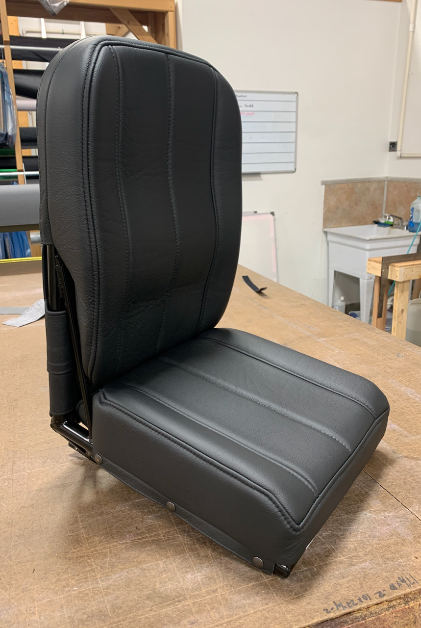
There have been several options over the years for seat upholstery, but in recent times one provider that has emerged as a bit of a Bearhawk specialist. Dan Maccarone of Sport Aircraft Seats has been in the airplane seat business for 21 years. At the age of 17, he and his brother started making seats for 135 operators in bush Alaska. They soon saw demand for an option that operators could install on their own in the field, minimizing down time. They created a system and it has grown from there, currently to 60 seats per month, shipped around the world. Dan has delivered several sets of Bearhawk seats, having had builders send seat frames to his shop at the Wolf Lake Airport in Palmer, Alaska. To make things easier, Mark Goldberg has sent a sample of each kit seat frame to Dan, allowing Dan to make templates and skip the frame shipping for future orders. Each kit consists of everything you need to upholster your seats from the frame up. They will have foam inside of upholstery that snaps or velcros to the seats, plus a tough herculite webbing system to support the cushions. Eventually he’ll have a fancy ordering interface on his website (sportaircraftseats.com) like he does for the other aircraft types, but for now just call him at 907-382-1230 or fill out the form on his website. The other types will give a good sense of how the colors look, since the Bearhawk seats will be very similar to the others. He can do single or dual colors in textile or leather, with or without seatback pockets. The colors look really sharp and there is enough variety to match the rest of your decor. The second-most important question is, are they comfortable? Last week I had a chance to fly the Bearhawk Companion from New Hampshire to Virginia, and my first leg was 3:45. I never flew a leg that long in my airplane. That brings us to the final important question, price. The more frugal of builders will not find his pricing cheap, but if you’d like to have more context, be sure to get a quote from a place like Oregon Aero. Keeping in mind that his package includes covers, foam, and suspension, and having done some of the seat work in our plane ourselves and not having it turn out as nice as Dan’s work, I think there is a lot of value. Pricing varies by options, but to give a range, single occupant seats in one color fabric are $925 per seat, or $1300 for two-tone leather. Rear seats for the 4-Place and Five are $1300 for single fabric up to $1850 for two-tone leather. He says there is a little more material in the bench seats but the labor for one bench seat is only a little more than the single seats, which is reflected in the price. Patrol and LSA rear seats fall between the bucket and bench seats for pricing. I’m glad to know that we have Dan as an option for good seats!
Continue reading

New Seat Adjustments for the Bearhawk Five, Four Place, and Companion

Source: 2021 Q1 Beartracks, From Mark Goldberg
For a few years I have requested that Bob consider redesigning the front seats for the four place Bearhawk. We wanted to improve the seats so they would be more easily adjusted while you are sitting in them, rather than “ground adjustable” like they have always been.
Bob came up with a very nice system where each seat slides in a track with four ball bearings. The same bearings are used in the aileron bellcranks of the four place. These seats slide aft to be removed unlike the original design where the seats slide forward to be removed. As you can see, the pins that lock the seat in place are on the top and visible unlike the previous design that had the lock pin mechanism on the seat bottom. It took a little back and forth between Bob and the kit factory to get them the way Bob wanted. While I have not tried them yet myself, the factory workers are very impressed. They have adapted the new design (with a few dimension changes) to the four place and Companion as well. The latest kits from the factory will incorporate this new feature.

Seat Installation in the Bearhawk 4-Place

Front Seat Adjustment Mechanism
As the seats come to you, there is paint inside the tracks that are part of the airframe, both the channels at the rear of the seat and the “ears” at the front. This paint should be sanded out to ensure smooth operation. Also, the “ears” may need a little tweaking to make sure there is sufficient clearance for the seat rails because they sometimes pull in while being welded.
Installing the seats is pretty obvious, but the locking pin mechanism requires a little study. There are two variations of the seat lock mechanism. Early airplanes have an ear welded to a sleeve that clamps to the tubing sticking down under the seat. The later version has the ear welded to the tube under the seat. The ear faces forward.

The T-shaped handle faces forward under the seat and pivots on the ear and presses down on a fender washer bolted to the bottom of the shaft. Put a hardware store spring in between to provide tension. There are two lengths of T-handles, the short one goes under the right seat, to clear the flap mechanism.

This is the way the seat latch looks from the front, when assembled. The short “T” handle goes under the right seat to clear to the flap handle. Drill holes in the track on 1” intervals.

There are several ways you can go about making up the cushion supports, but the way that we find most effective and lightweight is to use the same type of fabric you would use on the exterior of the fuselage. The human form is pretty blunt where it hits the seat, not a lot of sharp corners usually. Plus the cushion is between you and the support platform. For that reason, using Dacron and fabric glue, like PolyTac, is absolutely up to the task and it is the lightest way to suspend the flight crew. When it comes to cabin furnishings in general, beware, upholstery is dead weight and detracts from performance, so make it light. Also, don’t run upholstery over outside edge of seat as clearances are very tight.

Foam for Padding
Almost any type of foam can be used on the back but on the bottom. A memory foam such as
“Temperfoam” be used. It weighs a little more but has better shock absorbing capability. When building the seat cushions remember that this is where you fine tune the seating position to suit the leg length and sitting height of you and your passengers, so have the rudder pedals in place before doing the seat cushions. Regardless of the type of foam you use, a good tool for shaping is a kitchen electric carving knife like those intended for slicing a giant ham. Some foams can also be shaped with aggressive sandpaper in a power sander, but practice on some scraps first.

Installing the Back Seat
The back seat is secured to the floor by four special bolts supplied with the kit. Some kits have specially-made bolts with thick tabs welded to the top. Some use eye bolts. These thread into the four bushings welded in the floor. In early kits, these holes in the fuselage must be tapped (threaded) for the bolts. Later kits are already tapped. There are two different sizes of bolts used, 3/8 in the back, and 5/16 in the front. If you’ll be tapping the holes, run a drill bit of the proper size (Letter I and Letter Q) for the 5/16×24 and 3/8×24 taps. Approach the tapping operation carefully and with a lot of patience because getting in a hurry will result in a broken tap, which isn’t easy to remove. Keep in mind that you’ll never break a tap as long as the top of the tap and the bottom of the tap are rotating at the same speed. The bushing has been welded on, which causes it to be harder in some areas than others and where it is hard, it can be very hard, and will resist the tap. So proceed slowly. The key to success is lots of cutting oil and a tapping method where you turn the tap only 90 degrees at a time and back it up 45 degrees after each rotation. If you stick to this, you’re very unlikely to break a tap. Don’t yield to temptation and try to speed it up or force it.
The rear seats can be cross-bolted into position or, if you plan on removing them often, use “pit pins,” those are usually T-shaped pins with a push button in the middle that retracts two balls in the pin allowing it to be withdrawn. These pins are available from B&B in Kansas.
More pictures courtesy of Dave:

Bob’s Rear Set Design

Source: 2001 Beartracks, Bob Barrows and Mike Meador

After flying N33RB for over a year as a two seater Bob decided to design and build a rear seat for the aircraft. This design is very comfortable and easily installed and removed using the cargo tie down rings. If you have the Utility Door Drawings you will want to build this seat to make your Bearhawk a 4-seater.

2000 Beartracks Mailbag: Q&A with Bob

Bob, Enclosed is a check for Bear-Tracks for another year. I do have a few questions:

1 – What is a good method to use to transfer the airfoil shape to the wood to be used for the form block for the wing ribs?

2 – What is the recommended radius for the wing rib form blocks? I believe that 1/8″ would be about right for both .025 and .032.

3 – Do you have an e-mail address and if so do you answer e-mail correspondence?

I have a piece of 1″ thick hard maple for the form block. I just need to transfer the airfoil shape to the wood and cut it out. I am ready to start with the ribs. Is Proto II in the air? I bet the performance is really great – Thanks for your time.

Paul Foster – #289 – Monte Vista, CO

Paul, Thanks for your questions and newsletter renewal. As for your questions

1) The best method to use is to glue drawing #7 to your form block with contact cement or Plyobond.

2) a 1/16″ radius will work best for both thicknesses of the aluminum.

3) I do not have an e-mail account. Proto II is flying great -look for a flying report in this issue of Bear-Tracks. -Bob

This letter was pulled from the Bearhawk E-group. For more information on the Bearhawk E-group see page 7.

Well, after several days of non-stop building, 023 is on the main gear. I stumbled across a new Scott 3200 tailwheel in some stuff my Dad purchased from someone’s attic. He got a bunch of stuff (including a 65 hp engine, prop, landing gear, etc) for less than the price of a new Scott! What a deal.

Anyway, related to tail leaf springs, after much discussion and some consulting with Bob, I have decided on purchasing a PA25 tail spring from Univair (part number PA25TWS1) for approximately $90. 1 decided on the PA25 because Bob recommended two leafs all the way to the tail wheel bolt. Taper rod was attractive but with the Scott tailwheel, side loads should not be a big problem – it will go to full swivel if a major side load occurs.

My plan on putting a Continental 0470 on my Bearhawk has been changed. Finding an engine mount damaged or not – is not easy. Any found, even damaged, seem to run between $500 & $700. The Lycoming 0540 seems easier to make an engine mount following Bob’s newsletter. Also, Bingelis only talks about Lycomings!

Compressing the landing gear shock strut took some thought. I used a bar clamp – very long – and it worked fine. Later Bob told me he used his drill press with the table moved off center – I wish I thought of that! Oh well, some days I make things harder than necessary.

Piper TriPacer Seats also took some work to find. I ended up paying $60 each – frames in very good condition and but they need covering. Seemed like allot but finding seats was not as easy as hoped. Salvage dealers did not have any. My source has a couple more sets if anyone is interested.

Well, that’s my story for now. If anyone is near Cincinnati (actually Florence, KY) or Elkton, Ky, let me know. I build my parts in Florence and assemble in Elkton. It would be great to have some other builders close to discuss building, etc.

Bill Johnson – #023 – Florence, KY

Hi Bob, So glad to hear that you are ready (perhaps already have) to fly #2. Our second wing is going together quickly. Should have both sides, including control surfaces before the end of the year. Looking forward to starting on the fuselage.

The photo is my left wing with control surfaces installed. I am starting to look for a wind damaged Maule or C180/182 to scavenge for the engine and other needed parts. Still having a ball with the whole project.

Pat Fagan – #232 – Pearblossom, CA

Also from the Internet -I have most of the systems hooked up or at least roughed in. All the flight controls are working. I am finishing up the fuel system now. #75 is being powered by a (1996) Ford Taurus 3.0 24 valve engine that I modified with a polybelt GT. The engine has run with no propeller but hasn’t been run to RPM or load yet. Items needing to be finished are the fuel system, engine control linkages, a few things left on the cowl, and trimming everything. I am installing a removable interior for complete inspections in the future. I know that a lot of little details need to be worked out yet.

I am in the process of moving again. This time I am going to build a house and hanger at an air park. I hope to continue working on the Bear hawk through out the house project and get it in the air by at least late summer. How is everyone else doing on progress?

I will be happy to answer any questions the group has and give my opinion of what I may have done different. I will say as far as the plans I have followed them to the line and had very good results, The project gets more interesting when you start to improvise beyond the main part of the plane, i.e. engine controls and all the other goodies. Enough for now. Happy building.

Tom Yeoman – #075 – Apache Junction, AZ

Hi, Bob,
Things are moving along, not on schedule, but forward.

I was saddened to hear of Ray Thurston’s passing – It was like hearing about a family member.

The enclosed picture shows the flanging tool I used for the rib “holes” – it was made from a standard flycutter and worked great! The wood handle was used to exert pressure on the bearing. Steel washers were glued to the form bloc to serve as bearings for the center pin. This might be helpful to other builders so I am passing it along. All the Best,

Walt Draxler – #082 – Arlington Heights, IL

Bob, I hope this letter finds you and Mike in good health and fun flying in your Bearhawks. Enclosed is a check for my newsletter renewal – I have been so busy that I forgot to send it in. I’ve finally got a good start on my Bearhawk. I have all my small steel parts cut out. I am just finishing all my ribs and I am about to start on the wing spars. My goal is to have the wings done by the beginning of winter. I am enclosing some long overdue pictures of my project. I will be looking forward to seeing you and Mike at EAA again this year. If you need a place to stay for a couple of nights you can stay at my place. I am about 40 miles from Oshkosh. Maybe that is too far, let me know. I sure would like to hear your comments about my project. I can take criticism. I hope to have the wings framed up by then. I have a question about the fuel tanks. I noticed in one of the newsletters that you weld and rivet them. Is the riveting necessary? Can I just weld them? Is the riveting for added strength or just to hold them together for welding?

Ray Gabriel – # 334 – Greenleaf, WI

Ray, thanks for the nice letter and your newsletter renewal. Your parts look very good in the photos that you sent. Mike and I might be able to stay over at your place for one night while at Oshkosh, check with us at Oshkosh. It would be interesting to look over your project. The rivets in the fuel tanks are only to hold the sheets in place for welding. ~ Bob.

Ray Gabriel using a Liebert Hole Cutting Machine. Ray reports that a user can cut all the holes in all the ribs in about 3 hours with this machine. Also pictured are all the 4130 steel and a few of the aluminum parts ready for bending and drilling.


Bob, I have been meaning to write for sometime to thank you for the information in your newsletter. I have been working on my seating arrangement. The front seats incorporate a “captain’s table” arrangement for the mounting. Adjustments are made by pulling a side lever to the right and sliding the seats back and forth. The back of the front seats fold forward to allow entry to the rear passenger area. The back of the rear seat is adjustable. I used 3/4″ x .035 square tubing for the windows and door frames. I know that it costs a little more but it sure is easy to work with. I’ve got to relocate the rear window frame 2″ higher.

The engine is a Lycoming 0-540 of 235 HP. It will be pulling a fixed pitch McCauley 8452 Prop. I hope to have it up and running by October 2000.

George Anderson – #153 – Daphne, AL

Hello Bob, Just got the Jan 2000 Bear-Tracks. I am always looking forward to receiving the next issue. Sorry that we didn’t make it to the fly-in in Oct. We were planning on coming down to the fly-in and visit relatives but I came down with the flu – so maybe next time.

Thanks for the information in the newsletter – It must be nice to have two Bearhawks!

Thank you for coming to our cook-out last summer and I hope you can make it to our next one sometime in June this year. Since the cook-out there have been 4 of my neighbors talking about building Bearhawks. My daughter and son-in-law are planning on building one as soon as they finish their Cessna 140. We might have to change the name of the airport from Hale’s Landing to Bearhawk Landing!

I have been busy working on the 1959 Cessna 172 that I am restoring – it’s almost done. The Koala 202 is almost ready to cover and I have most of the 4130 steel hardware for my Bearhawk wings made. I have too many projects and not enough time or money to finish them all.

Do you have plans for any future modifications for the Bearhawk? If so what? How about plans in the newsletter for seat frames and tracks. I have found that the Tri-Pacer seats are hard to find.

Dan Riffee – #267 – Hale’s Landing, WV

Dan, Sorry to hear that you were sick and couldn’t make it to the fly-in. Like you say maybe next year. Mike and I really enjoyed our trip to Hale’s Landing last year and are looking forward to it again this year. When you firm up a date – let us know.

Currently I have no more modifications to the Bearhawk design planned. Your idea for seat drawings is a good one and I will work on that for a future newsletter. -Bob


Bob, Enclosed is a check for the 2000 newsletter, also I have a few questions:

1) The part of the nose ribs that form the leading edge, have you noticed on the prototype or do you forsee a problem with fretting because the metal is not secured together at the leading edge tip?

2) On the plans it calls out a 1.25″ flange on the main spar and a 1″ on the rear. The newsletter has instructions for laying out spar blanks : Width = web finished height PLUS 2 x flange width PLUS 1/16″. This will give a larger flange than calls out in the plans, the same also with the 9/16″ and 1/2″ marker for the rib flanges. I wonder if it makes a difference or would I have clearance problems later?

3) Are the spar webs square on both ends or do the root ends have the shape of the wing attach fittings to fill the gap between the fittings?

I have started slowly on the wings, having trouble getting consistently sized ribs but getting there, I have all my tools and shop set up so far and having a lot of fun.

Mark Skiba – #349 – Camarillo, CA

Mark, Looks like you are really getting into the drawings and giving them a good going over. As for your questions: 1) Fretting has not shown to be a problem on the prototype and I don’t see any indication that it would start. 2) Slightly larger or smaller flanges will not cause a problem. 3) The spar blanks have the shape of the wing attach fittings.

Your ribs should be consistent within about 1/32″, let me know if you are still having trouble with the ribs. Maybe I can give you some more pointers for rib construction. ~ Bob

Mike and I received notice that Ray Thurston’s #005 BEARHAWK project has been purchased from his estate by John H. Dugdale. Ray had completed a tremendous amount of work on his BEARHAWK and it would have been a shame to see it go to waste.

Hi Bob,

I’m making good progress on the BEARHAWK. I’m on the wheels and rudder hook up to the pedals (I had to move the rudder pedals back from the firewall for brake cylinder clearance). I have a 0-470 and Prop and a good lead for the mount.

The seats are installed and I’m rigging up the rest of the tail. I have included a few photos of me forming the T25 ribs 1/8″ bend with a steel mandrel on the anvil.

Do you have a date for the fall BEARHAWK Cookout?

Will Graft – #365 – Wadsworth, OH

Wil, good to hear from you. I mention the distance used on my rudder pedal setback on page 5 of this issue. As for the cook out – we are still working out the best date as October has suddenly become very busy. We will have a firm date by Sept 1. ~Bob


The following post is from the BEARHAWK e-group.

Today I had to go see the IA who helped my brother restore his Citabria and I mentioned the e-mail list discussion of reverse engineering a set of EDO floats. The one hassle which he could see, would be forming the “hoop” stiffeners which give the rounded top of the floats their shape. He showed me an old partially torn up EDO and it looked like they were formed in a brake and then formed into their rounded shape, similar to how the fuel bay wing skin stiffeners are made for the BEARHAWK wings, only with a LOT more curve. So it would be a lot of trial and error compensating for springback, and it would have to be redone for each size hoop due to the taper of the floats. Not an insurmountable challenge, but probably easier to copy a float with flat top and sides.

He did mention that in the EDO line the model 2425 is not rounded like the others, and might make a good candidate for duplication. If the model number is also the displacement, that might be a bit on the small side, but may be close enough if you don’t increase the gross weight above what is specified for the landplane version.

Other than the hoops the rest of the float looked pretty straightforward and ought to be easy to copy if you could get the right extrusions. The one thing I noticed was LOTS and LOTS of closely spaced rivets. I think I would prefer to build my floats in fiberglass if a set of suitable plans become available. Matter of fact, my friend the IA asked “why don’t you just design your own?”

Del Rawlings – #316 – Cordova, AK

Bob,

#232 is really coming along well now. I bent the top frame as you suggested and was pleased to find everything lined up! I almost have the entire frame tacked together.

I was wondering, do you call for any special bolts, like close tolerance or high strength in the wing struts or landing gear?

I am planning on an 0-540 for a powerplant, will any 0-540 core serve for setting up my motor mount or do I need the actual engine?

Pat Fagan – #232 – Pearblossom, CA

Pat, good to hear that the process worked, as for the special bolts question, the answer is no. The airplane was designed to use standard AN hardware. The actual engine would be best – short of that, make sure that the engine that you use is set up the same as your core and that it has the same mounting bosses that match your motor mount ~ Bob

Another note from the e-Group:

Has anyone perfected the “Barrows Method” of flanging the @#$% lightening holes?

Mike’s book as well as “BearTracks” makes this look real simple.

“Barrows” Method:

1. Wax it up.

2. Using the flange tool, lift the hole 30 degrees by smoothly going around it about 2-3 times.

3. Flip the rib over and push it down with the back of your flanging tool to lock in the 30 degrees and tame any bends.

4. Sit back, admire your work, and realize that you’re God’s Gift to the Bearhawk community and builders world over.

“Romanko” method:

1. Wax it up. (Even I couldn’t screw up this step)

2. Fail at smoothly taking the flanging tool around the @#$% hole. Instead, use the flanging tool like a soda pop opener and go around the @#$% hole lifting it up in increments equal to the width of the flanging tool.

3. Admire all waves you just put in the @#$% hole.

4. Wax it again, and go around the @#$% hole with the flanging tool, realizing the waves will never come out.

5. Flip the rib over and push the waves with the back of the flanging tool until you realize you really are having a hard time judging 30 degrees with your eye at 0400 in the morning. Induce more waves.

6. Sit back in amazement as you realize what was once a straight rib has turned into an oil can. Go outside. Look up. If you see stars, leave for the airport and get in some quick flying before work.

I know that some of you have built elaborate dies for forming your holes, but I really hate the thought of spending time doing that. Frankly, I’d prefer to keep everything “Barrows Simple”. I keep looking at Bob Barrows as my example. If he built THREE sets of wings using this method, it’s good enough for me. I think it’s just an issue of practice, but I really thought I’d have it down by now. Until I do, I will continue to refer to them as the @#$% lightening holes.

Bob Romanko – #399-Charlottesville, VA

Bob, Bob and I have agreed to conduct a personal workshop with you to perfect the “Barrows Method” of rib flanging. I got it on my first try. ~Mike

I found some rod ends at Sun & Fun for $12.00 each. Talked to the surplus dealer (Russell). He has about 1000 more of these jewels. The part number on the rod end is RE4H6-2 made by Fafnir (look at the Spruce catalog and you will see these are the right ones). If you would like to purchase, fax an order to Russell AT2 Surplus (847-432-6847). He said it takes time for him to fill orders so be patient.

Bill Johnson – #023 – Florence. KY

Bill, you look good sitting in that fuselage. I was able to confirm the rod end information with Russell – Order what you need builders! ~Mike

Bob, I’m enclosing some photos of my Bearhawk. I have completed the fuselage, both wings, wing-tips, fuel tanks (installed), nose bowl, and the seats. All cables are hooked up and operational.

I constructed the seats myself with 4130 tubing and
zig-zag springs for the seat bottoms and backs. They are fully adjustable front and back with a hinged back for access to the rear seat compartment.

I’m getting ready to mount my engine on the Bearhawk.
It is a Continental 0-470. I hope to have my Bearhawk in the air by next fall – God willing.

Things seem to be going very well building from your plans. I cut my first tube three years ago.

Sorry I missed seeing you and the prototype in May when I was on the east coast. Maybe it will work out better on my next visit. God Speed,

Boyd Newgen – 264 – Ontario, OR

Boyd, What a great letter to receive the day I return from Oshkosh! Thanks for all the great photos and keep them coming. I am glad to hear that you are making such good progress, ~Mike

Hi Bob & Mike, I have had the Bearhawk plans 5 years and I am only now just starting. I have done a Kitfox and a Thorp T-18 (which took People’s Choice at Oshkosh) in the early 80’s. I want my Bearhawk to do the same.

You mentioned that you stayed at Blackhawk Field in WI during your trip to Alaska. I hangared there for two years prior to coming to Oregon.

I am a steadfast promoter of the Bearhawk. Why someone didn’t think of it the 30 years proceeding Bob remains one of life’s mysteries!

Don Schindler – 068 – Springfield, OR

Dear Bob, Please send me a copy of the Utility Door Plans ($25 M.O. enclosed).

I have been studying the plans at great length, trying to create and assemble the aircraft in my mind. In this way I feel I will have an understanding of the aircraft as a complete idea and not just some parts to make and slap together. This activity alone has been a source of great entertainment for me.

I expect to be full bore into parts construction by the end of December.

I have a couple of questions for you concerning the plans – At the root end of the spars you show the .032 web is to be continued all the way under the spar end plates and the spar end inside plates. Also you show the web flange ending at the top and bottom of the spar slightly short of the corner angle of the end plates. this creates and inside right angle cut at the top and the bottom of the web material at the end of the flanges. Is this inside right angle cut a possible source of future web cracking from stress? Should I radius it or continue it as a gentle curve up to the flange?

Do the line diagrams of the fuselage tubing depict the inside, centerline, or outside of the tubes?

And finally are there any unusual cluster arrangements in the fuselage tubing joints?

Bion T. Rodgers – 436 – Mount Royal, NJ

Bion, You should have your utility door drawings by now – let me know what you think. As for your questions: You make a good point about the spar flange. There should be no sharp inside corners on ANY aircraft metal part. Use a 1/8″ radius or larger. The fuselage line drawings depict the CENTERLINE of each tube. And there are no unusual cluster joints used in the Bearhawk frame as designed. ~ Bob

Dear Bob, I was pleased to have made your acquaintance on the telephone the other day. As indicated I have purchased Ray Thurston’s Bearhawk project but have not yet collected it from Blenheim. I will collect it soon, in the meantime Mrs. Thurston has sent me the plans and I am studying these.

Ray has done a lot of work on his project and it is a tragedy that he was not able to complete it. I hope to be able to pick up where he left off and continue the quality of workmanship. I am not a trained engineer, but enjoy a challenge and have always had a “hands on” practical tendency to make and fix things – boats, engines, travelling irrigators amongst others.

We live on a small block (14 acres) about 14 miles from Christchurch. While we are within the Christchurch International Airport Control Zone, there is a possibility we could fly off the block (it is 515 meters long (that’s 1690 feet to you and me)). The big thing will be to not annoy the neighbors as the area is in the process of being divided into smaller and smaller blocks with people moving here from the city.

So far as the Bearhawk is concerned, I have not decided what engine to use yet. Personally I am not keen on air cooled engines, but there is considerably less work and less uncertainty involved in sticking with the Lycoming. I am also not keen on reduction drives as many of these seem to have some problems. I quite like the idea of an inverted, direct drive, alloy V8, such as Steve Whitman used in his Tailwind. No doubt this would take some development too. A Rover 3500cc can be stoked and resleaved to give over 5000cc and this would give enough HP, but this too would take some development.

I would appreciate if you could provide me with a bit more specific performance data re: the Bearhawk than is contained on the websites. If this has been published in the newsletters do not bother to repeat it (I am awaiting receipt of the back issues from Mrs. Thurston). I am interested in the specific performance of the prototypes – e.g. estimated HP of the engines and the cruise speed at 2400 RPM for each, climb rate, fuel burn at cruse. Do your take off and landing figures represent literally lifting off the ground or are they the traditional 50 foot obstacle clearance? Also can you supply some data on the Bearhawk’s ability to handle cross winds. I look forward to meeting you someday in the U.S. or in New Zealand

John Dugdale – 005 – Canterbury, NEW ZEALAND

John, Thank you for the introduction and I hope that you find the Bearhawk to be to your satisfaction once you begin construction. I considered Ray to be a very good friend even though he was on the other side of the planet and I am pleased to learn that all his hard work will not go to waste. I think that you will find the answers to most of your questions in the back issues of the newsletters. My performance figures represent actually lifting off the ground. I personally think that the Bearhawk handles crosswinds quite well. The nearest production airplanes that would be close in crosswind competence would be the Husky, Super Cub or Citabria. ~Bob

1998 Beartracks Mailbag, Q&A with Bob Barrows

Source: 1998 Beartracks, Bob Barrows

Dear Bob,

This is a formal invitation to come visit us in this area on your trip to Alaska. It is sure to be an exciting adventure and I am envious of you actually planning it. I often talk about going to see my old flying instructor (Ray Krumrey) in Old Harbor, Kodiak Island but haven’t got there yet. It is one of my flights of fancy to fly there in the Bearhawk and do a big impression on him. Ray is a great guy and we became good friends as a result of flying.

David Giles (#222) wants to meet you. He is an SDA Minister who flies an RV-6 he built and is barely started on the Bearhawk his son and he are doing. He is a really nice fellow – one of your fellow Countrymen originally – and he visits me fairly often. I’m sure that there are others who would like to meet you too. Another reason for coming is that you will be right on course for the “Rocky Mountain Trench” which will take you right to your destinations in Alaska. It will be a comfort to you to know that you will be flying over a lot of paved road (emergency landing strip). Be advised that GPS is definitely a good idea as there are very few other Nav aids in this North Country once you get 300 miles North of the Border. I haven’t actually been over but I am told it is great!

Progress on the Bearhawk is slow and steady. My Son has already dubbed it with the moniker “Times Two” since I have made so many things twice! I keep telling him that those were “test pieces”! However, the fuselage is largely done and I am working on the little bits and pieces necessary before I move it off the reference plane of the dead level and flat workbench I built from three 16ft TGI floor truss crops. Used 4×4 legs with adjustment bolts in bottoms. Covered top with 4×8 plywood with one foot overhang. Using other shipping plywood, I made shelves between the truss ledges. This works well as they slide out and is a handy place to store pieces of tube right under the bench top. Simple, strong and flat and it can be disassembled as I put the legs on with lag bolts and left about 4″ edge overhang!

Have all the wing pieces built but have not done any skinning of them. I got tired of pounding aluminum and switched to building the fuselage. This winter I hope to make the tanks and a lot of the hardware pieces like seats, controls, levers and such. The main idea for me was to have a project to keep me out of mischief! It has worked but I have also derived a great deal of enjoyment and satisfaction from building (to this point).

Bill and his wife spend their winters in Arizona. He got me onto this design of yours and has been a great resource with all his experience. He and another of his friends are building an RV-6 each. He likes to get upside down once in a while, he says! He sold his Stearman. The Airline driver who bought it had to get some old timer to fly it back East because he couldn’t handle it. After getting it home, the nerd wrecked it within a week! Wheel landed on wet grass area and hit some puddles of water. End of story! $50,000 later … ??? All the best,

Rod Dressell – *190 – Creston, B.C.


Dear Bob,

Do we need to consider increasing the vertical stabilizer/rudder size, or add a dorsal (ventral) fin for use with floats?

Thanks,

Bob Thomasson – #280 – Santa Rosa, CA

Bob,

The rudder will not have to be altered in size to accommodate floats. The vertical fin area may have to be increased to counter the side area of the floats. A dorsal fin bolted to the bottom of the fuselage will accomplish this. Weld in a bushing for a 5/16″ bolt at station G-K and use the tail spring attach fitting to bolt on the dorsal fin. I am not sure as to how much fin area is needed – you will need to experiment, and talk to other float pilots. Bob

Bob,

Keep up the good work, your newsletter is invaluable! … Still working on the wings.

Thanks

Brad Young – #229 – Spearfish, SD

Dear Bob,

Just a reminder that we wanted to be put on the list as one of those who would order struts from you. Fritz and I put the wings on last weekend. We had the fuselage setting sideways in my garage with one wing in and one wing outside of the garage. The door was covered with plastic sheet so we could heat the place. It took a day or so to get things squared up and the wings are off now and tucked away in their rack until next spring when we can paint them.

We hope to be done by the first of April ’98 if things go well.

Tom Lee – *98 – Winona, MN

Dear Bob,

Well, I’ve had your Bearhawk in the back of my mind since I read the Sport Aviation article 2 years ago. I poked around the airplane a OSH last year but never got to meet you or talk to you about it.

My RV-6 is almost rebuilt – after being run over by a Chevy, believe it or not – and I am contemplating a project where I can learn some new skills.

I work for Dick VanGrunsven and can get almost all the materials needed very reasonably along with access to all the metal forming equipment you could ever want.

So – what I’m thinking about is a minimal, light airplane – but with a battery and starter, hooked to the lightest six cylinder engine I can find. Say an 0-470? Do you think this is practical for a guy with minimal welding skills but good teachers?

Enclosed is a check for your flyer & – I hope – a collection of past newsletters. I write the one for Van’s, so I like to read other peoples! Addresses of Western OR or WA builders would be appreciated too. Thanks.

Ken Scutt – Hillsboro, OR

Ken,

Thank you for your letter and the request for information on the Bearhawk. It is interesting to hear that you work for Van’s Aircraft and write his newsletter.

Many builders of the Bearhawk are doing this airplane as a first time project and learning the skills as needed, from knowledgeable EAA members.

Please find enclosed a data sheet, photo, a selection of newsletters and a list of builders in your area.

Thank You – BOB

Dear Mr. R. Barrows,

I have received the drawings for the Bearhawk: The drawings are beautiful!

For your super excellent work – I send my graduation!

Yours Faithfully,

#209 Stefan Kjorcev-#308-Oberglatt SWITZERLAND

Tim Neal #209 sent in this photo of his project.


Bob,

A few questions as my fuselage is well on and I will need some answers to keep going.

1) For the rear door modification – you specify .032 alloy, would .025 be too light?

2) Will you be supplying a detail of the main doors in the newsletter?

3) What weight of alloy do you use for engine cowling – .020 or .025?

4) Routing of fuel lines from tanks and do you run separate line from the front and rear draw off points on tank and join to one in cabin or how do you do it?

5) Your method of attaching plastic sight tubes for fuel to alloy tank tubing?

6) Have you a fore and aft adjustable for front seats to seat long and short legs?

7) Some friends of mine at Oshkosh talked to you and took some good photos, a question on your exhaust system, by the photo: you appear to have 4 separate pipes, are they straight out and what is the noise like?

8) The trim system on your drawing #22; Do you need a friction disk or is there enough friction in the system? Is the trim chain a 1/4″ with a 12 tooth sprocket?

9) Positioning of wing attachment fittings on fuselage, the 32″ dimension is OK but the parallel dimension for both sides in relation to the spar fittings and lining everything up, my spar fittings are pilot drilled 3/16″, presumably the fuselage fittings should only be pilot drilled at this stage? These wings are quiet large compared to my Tailwind, so will you be giving a rundown on the fitting, lining up and setting dihedral, drilling and reaming holes to size, etc.?

10) Lift strut fittings, I have made up the wing end channel fittings, the double joggle in the fuselage end is somewhat more complex. What was your method of shaping? Also do you square cut the ends of the struts or angle cut to angle of wing and fuselage?

11) 1 know from a previous comment that you prefer a control stick and my Tailwind has a stick but I really want to have a yoke system with the Bearhawk. Much easier for females with a dress on and the floor remains relatively free of obstruction. Could I copy something?

12) Finally, the need for a fixed step up into the cabin like many aircraft have, my wife is not that tall.

Regards,

Ray Thurston – #5 – Blenheim NEW ZEALAND

Ray,

Good to hear from you again.

Regarding your questions:

1: .025 should be OK. 032 is better for the wear and tear resistance.

2: We will cover door construction in a upcoming issue of Bear-Tracks.

3: .025 is used. You may use .032 for the top.

4: The tubing is joined below lower front door frame with T section. (Upcoming newsletter)

5: Below is a sketch of what I recommend:

6: Yes – the same as a Piper Tri-Pacer. This system is nice in that as the seat moves forward it also rises lifting the shorter pilot up to see over the instrument panel, as it goes back the seat lowers giving the taller pilot more headroom.

7: I have 4 straight stacks out of the bottom of the cowling. I am told that they are loud but not unpleasant. I do wear earplugs.

8: No there is enough friction in the system.

9: See here.

10: I’ll cover the correct method for bending the end fittings in the next newsletter. Cut the strut ends square.

11: We do not plan to design such a system but you could copy the Tri-Pacer or a Cessna design.

12: A step is a builders option – check as designed on other tube fuselage aircraft.

Thanks for your letter and send us some photos of your project! ~ BOB

Bob,

I want to thank you again for your time and sharing techniques. I made another set of fluting pliers and they make a nicer crimp. I am also doing my rib lightning hole flanges a lot better, no warped ribs.

The idea of putting tape on the fluting pliers to keep from marking the aluminum really works. Thanks.

J.T. Newbegin – #284 – McAlpin, FL

Hi Bob & Mike,

Just got your newsletter, sounds like a lot of great activity with the builders. It also looks like you are getting close with Proto II.

I have enclosed a check for $250 for a pair of wing struts. I will be looking forward to getting them.

BEARHAWK 075 has fabric on it now. I am taping at this time and hope to have everything in silver in a couple of weeks.

The engine has not been installed yet, it will be a Ford Dura Tech 24 Valve 3.0 V6. I am converting the engine myself and have had to do a lot of searching to find an ignition/fuel injection computer system that I felt comfortable with. The original Ford system has too many extra input requirements and no adequate wiring diagrams.

After the engine is roughed in and the fuselage is on the gear I will send you some photos.

Have a great day!

Tom Yeomans – 075 – Richland, MI

Tom,
Sounds like you have made quite a bit of progress on your project. A lot of the builders may have an interest in more information about your Ford conversion. Keep us updated. ~ Mike

Chuck Frasier called the shop a few weeks back and had a question about the tail feathers. He was fitting up the elevator and found that the trim tab arm is rubbing the T-14 spar tubes on the horizontal stabilizer and the elevator.

To fix this you put a 10° – 15° bend in the trim tab arm under the elevator T-14 tube. You should clear the spars by a bit more than 1/4″.

Reference drawing #20.

Dear Bob,

Enclosed is a check for one pair of struts. I have finished a full review of the plans and worked out a material list. I bought all the .025 aluminum I’ll need and I am accumulating the other material.

Still trying to get my garage finished and other projects I had already started so I can start pounding out ribs. Is there enough strength requirement for using the 1/2″ X 1/2″ rib attach angles or can I make more than one forming block and bend up the end of ribs for attachment? I would rather make more forming blocks and save some weight unless the attach angles are required.

I have not seen in the October Sport Aviation article or in Bear-Tracks or in the plans any information on testing. Has the plane been flutter tested? Has the plane gone through flight testing such as dives to Vne, stalls at both ends of the envelope, light weight to gross?

Thanks for the help. Would sure like to see N6890R if you stop near Seattle on your way to Alaska this year. A visit to the Arlington fly-in would sure be nice for the west coast builders who can’t make it to Oshkosh but would like to see the BEARHAWK!

Wayne Hallburg – 266 – Centralia, WA

Wayne,
Thank you for the strut order – we will be shipping the struts (hopefully) before you read this. About your questions: Yes you can eliminate the angles if you wish but you must take into account the varying widths of the spars at different locations. The flutter testing was done during dives to Vne speed at 180 mph and stalls have been done at 1500 lb and 2400 lb gross with no unusual characteristics shown.

We are planning on attending the Arlington fly-in this year and hope to see you there. -Bob

Bob responds to a fax from Ray Thurston :

Ray,

In reference to your fax of 01/16/98 about the flap control assembly drawing #28: In checking the fit up on the BEARHAWK now under construction in my shop I did use the arm length as shown on drawing #28 but I offset it as shown below. In addition I moved the shock strut attach fitting (see drawing #24) up as high as I could and still have room for the rod ends HMX-76. This all gave me the clearance that I needed. ~Bob

Dear Bob,

Enclosed is a check for a pair of wing struts. I am also enclosing a photo for the newsletter. It is a picture of a die, made by Doug Jasper, for bending the flat plate pieces for the wing hardware.

It worked quite well and I think it is obvious how it works. He spaced the bars so that one side will bend .063 and the other side .080. I filed a radius on the edge of the male die, which is 3/4″ key stock, so one side does .063 and the other .080.

I just finished my steel wing hardware. I brought my flap and aileron mechanism to my EAA Chapter meeting last night and everyone commented on how nice they looked. Even had one person praise you for the engineering and how smoothly the mechanisms worked. I am now finally beginning to assemble my first wing. Slow but sure.

Pat Fagan – #232 – Pearblossorn CA


Dear Bob,

I am confused about the turnbuckles for the elevator where connecting to the bellcrank.

Drawing #26 says AN 135-32S Turnbuckle. I just ordered as specified and find on arrival when I was doing a trial fit that the pin eye is .25″ and yet the bellcrank says 3/16″.

The Cable eye likewise seems larger than required at .281″.

All parts are stamped and the turnbuckle is definitely AN135-32S. Would AN135-16S be more appropriate? Could you let me know?

Ray Thurston – #005 – New Zealand

Ray,

The AN 135-32S as called for in the plans is correct. You will need to make a bushing from 1/4 ” x .028 4130 tube, and use (2) AN960-416 washers as shown. ~Bob


While at Sun N’ Fun several builders brought pictures of their progress. Below is a photo of Larry Williams #184 project. Larry is using a Continental 0-470 for power. ~Bob


Bob,

I received the wing struts Saturday and the plans for the struts a few days later. Thank you. I received the cap strip material I ordered from Wicks last week and I bought some rivets to practice with over at the fly-in and flea market at Hampton Airfield on the coast of New Hampshire. I am a little nervous about starting the spars but I am sure that it will all go fine.

A friend of mine has landing gear and the gear shock struts that go on a 1947 108-2 and we were wondering if it would work on the Bearhawk. If so is it as strong as your design. What are your thoughts.

Sonny Cilley – #234 – Royalton, VT

Sonny,

I am sure that your spars will come out fine. It is just a matter of following the directions on the plans and in the newsletters.

The 108-2 landing gear system that you have is strong enough for the Bearhawk – but doing the engineering work to install them would be quite involved and time consuming. The time spent adapting the Bearhawk to accept the Stintson landing gear would be greater that just building the gear shown in the drawings. ~Bob

Bob & Mike,

It was great meeting both of you at Palmer, Alaska and I immediately dived into the plans and newsletters. Wish I had had the chance to study before going to Palmer but that is life in the frozen North.

As stated at Palmer, here is my check for a set of struts and drawings. I also want your wing construction and photo log, which will answer many procedural questions, I’m sure. May as well get the Disogrin ring set as I don’t want any delays for parts. While I have not yet ordered my 4130 and Aluminum, I have sent for all the books and catalogs recommended, made up a material list, made the wing rib form and acquired jig material (table) and a good shop to build in. All this since getting back from Alaska on August 12th. Being retired has its advantages.

I was in Alaska for about two months installing the water wheel power project for my friend. We are still evaluating the project, though the initial data
is quite favorable and slightly exceeds expectations after some modifications.

Hope all is well in Fincastle, do you think you might do Arlington again next year? I would like to have a list of Washington builders list and when available. In the meantime I will be attending the local EAA chapter meetings which I understand is loaded with talent.

Is there a drawing for the float hard points?

Just so I don’t miss any bets, please let me know your pricing for an 0-360. Thanks and looking forward to building.

Jack Piggott – #347 – Sequin, WA

Jack,

Thanks for the photos and letter. The struts have been mailed out along with the drawings and the o-ring seal kit. You should unwrap and oil down the struts when you receive them before putting them in storage. Mike has sent you a photo log that you should receive soon.

It sounds like you have really been chugging along on your project. Keep up a good head of steam because it is a long haul.

Regarding the float attach points, see the 1996 issue for rear float attach location, and use the front landing gear fitting for the forward attachment point. The fitting at the rear can be made just like the landing gear fitting if you like. We will work more with you on this area as needed. Do you have any idea what kind of floats you will be using? ~Bob

Mr Barrows,

Just a letter of introduction that is long over-due. I recently purchased plans s/n 188 from Mr Serge Valin the package also included the photo log and newsletters to October 1996. Enclosed is a check for all the back issue that I am missing and a subscription for 1999.

With any luck this winter will see me pounding out ribs. If there are any builders that are close to Detroit, I have access to a 10′ shear and brake for spars.

Mark Deacon- *188 – Brownstown, MI 734/789-1196

Mark

Your newsletters are on the way. I’ve included your phone number for builders in your area that may want to get in touch with you regarding the 10′ shear and brake. ~Bob