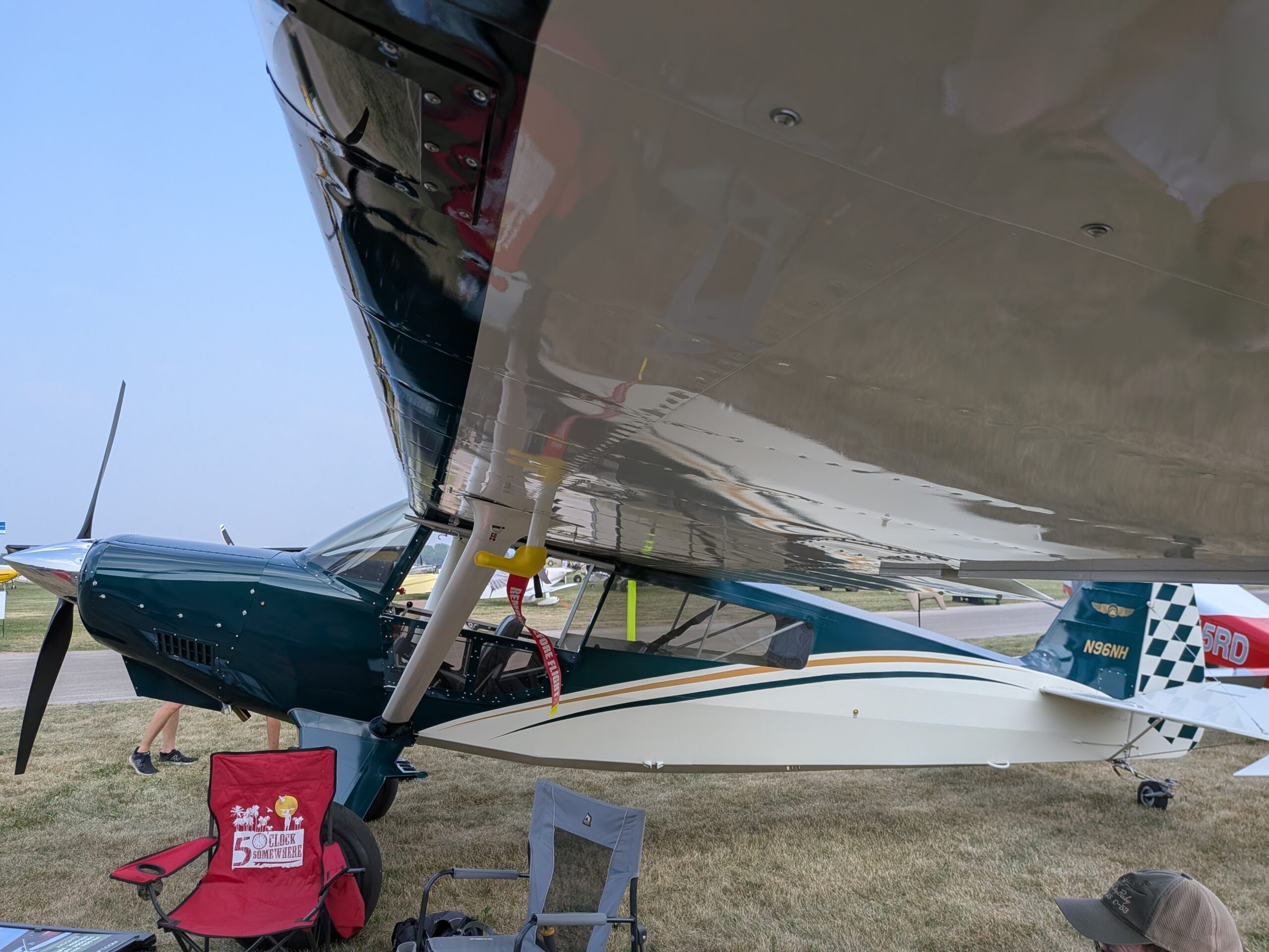
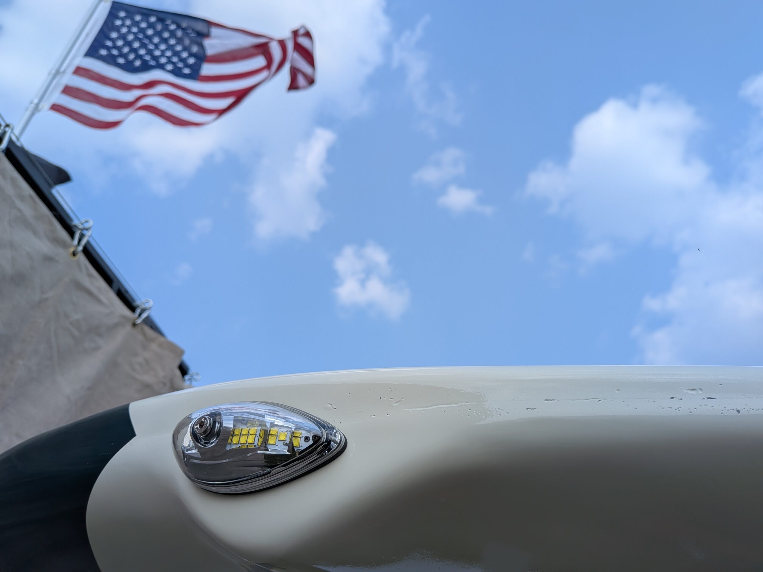
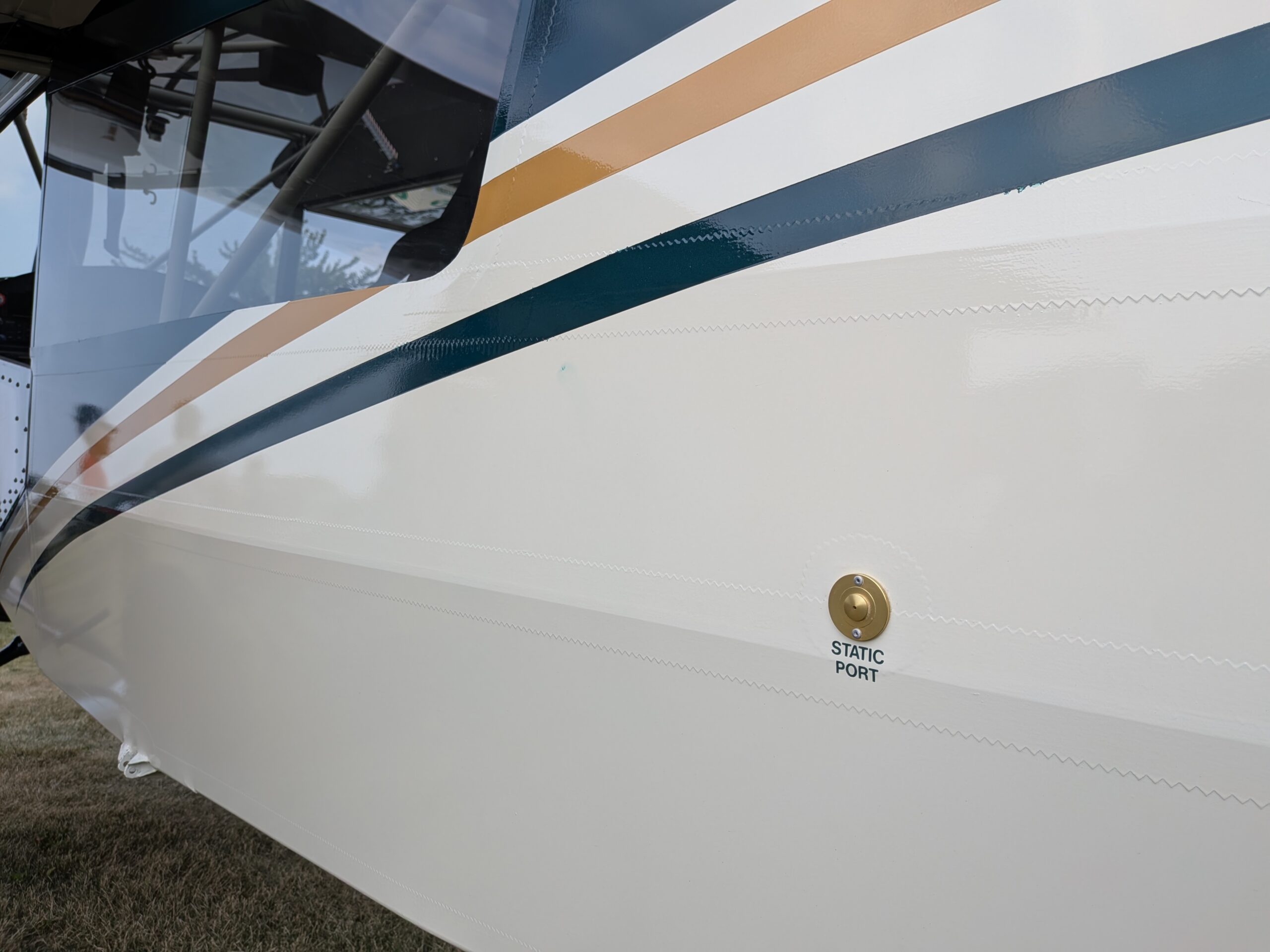
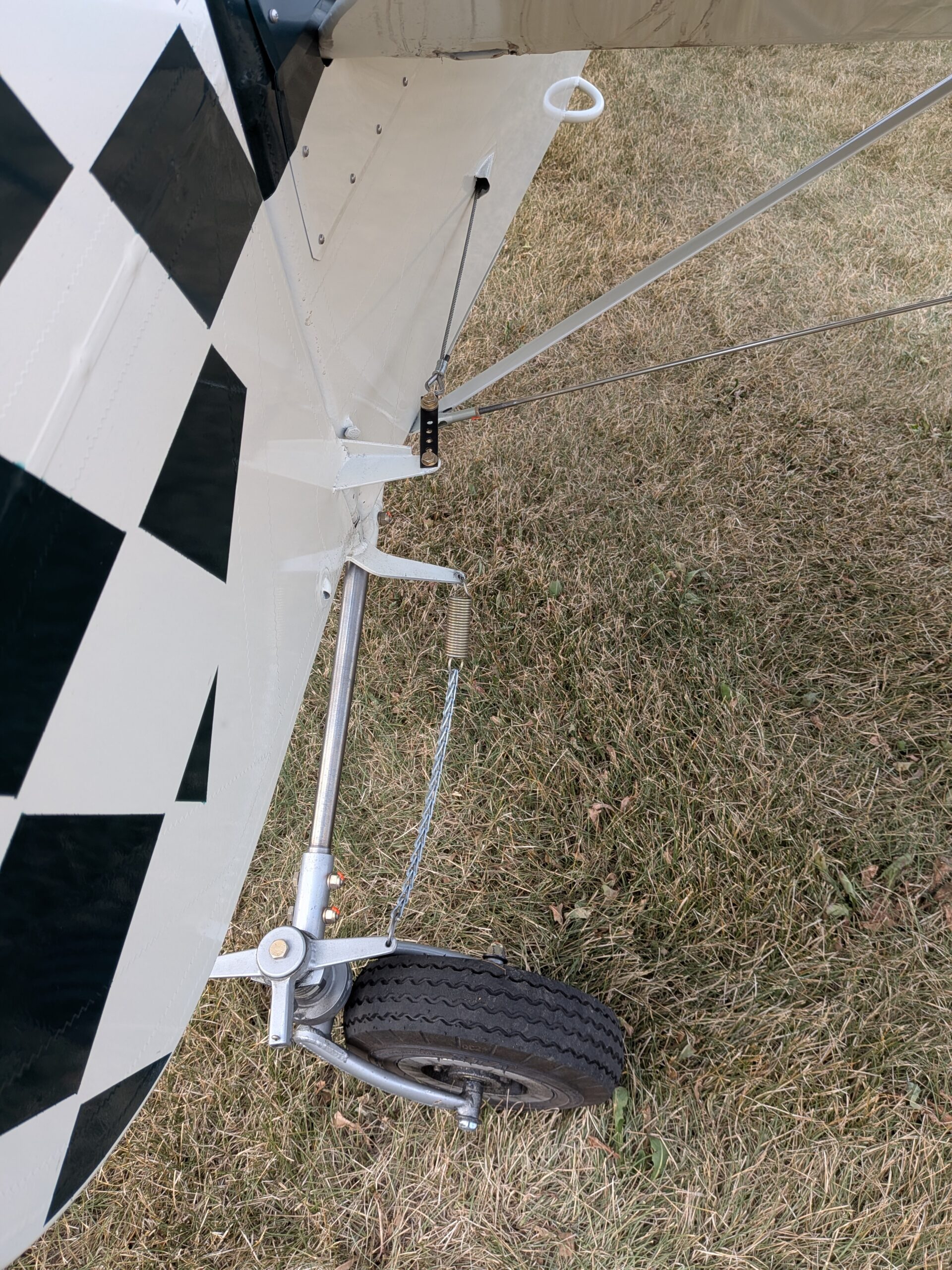
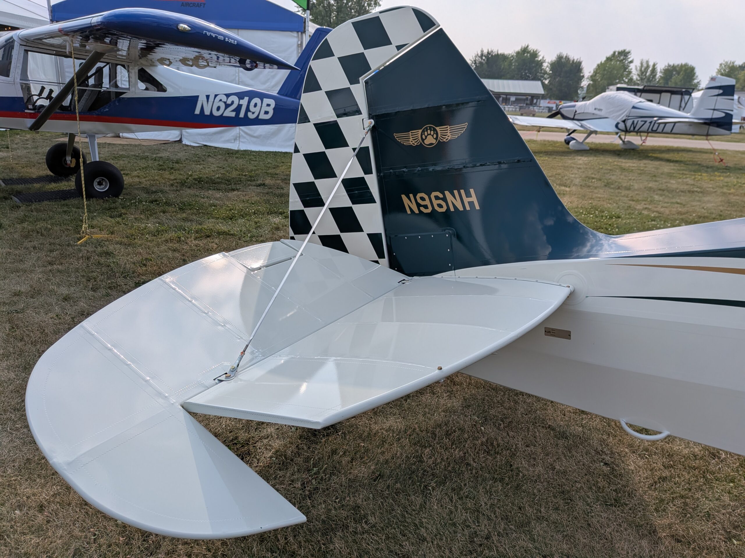
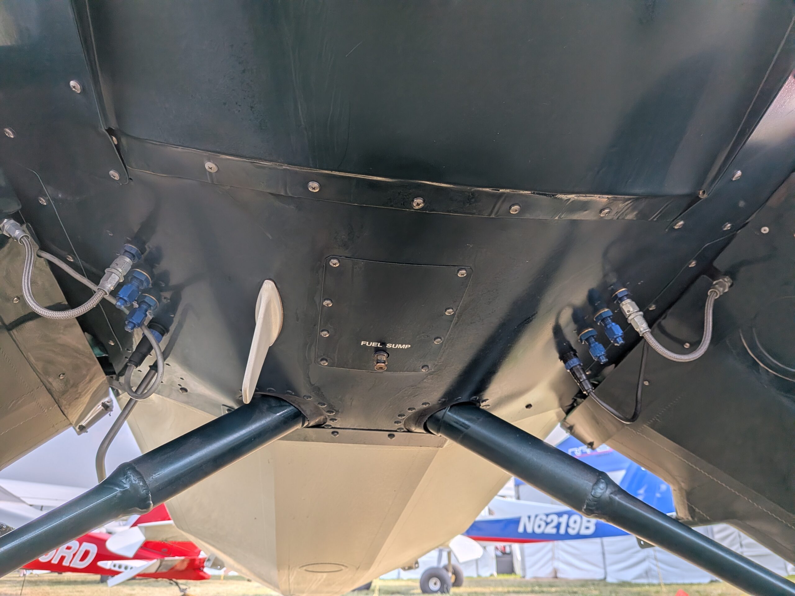
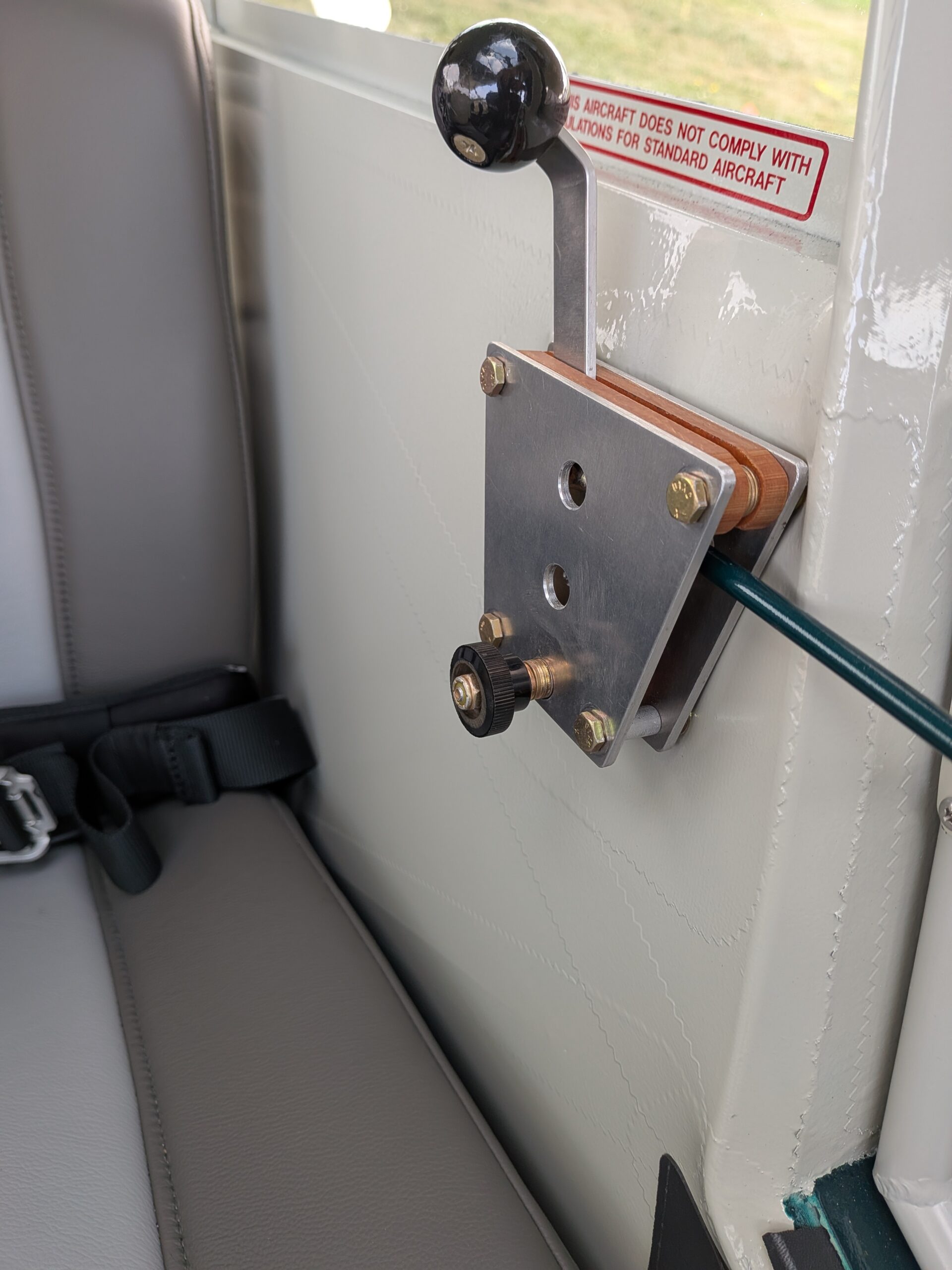
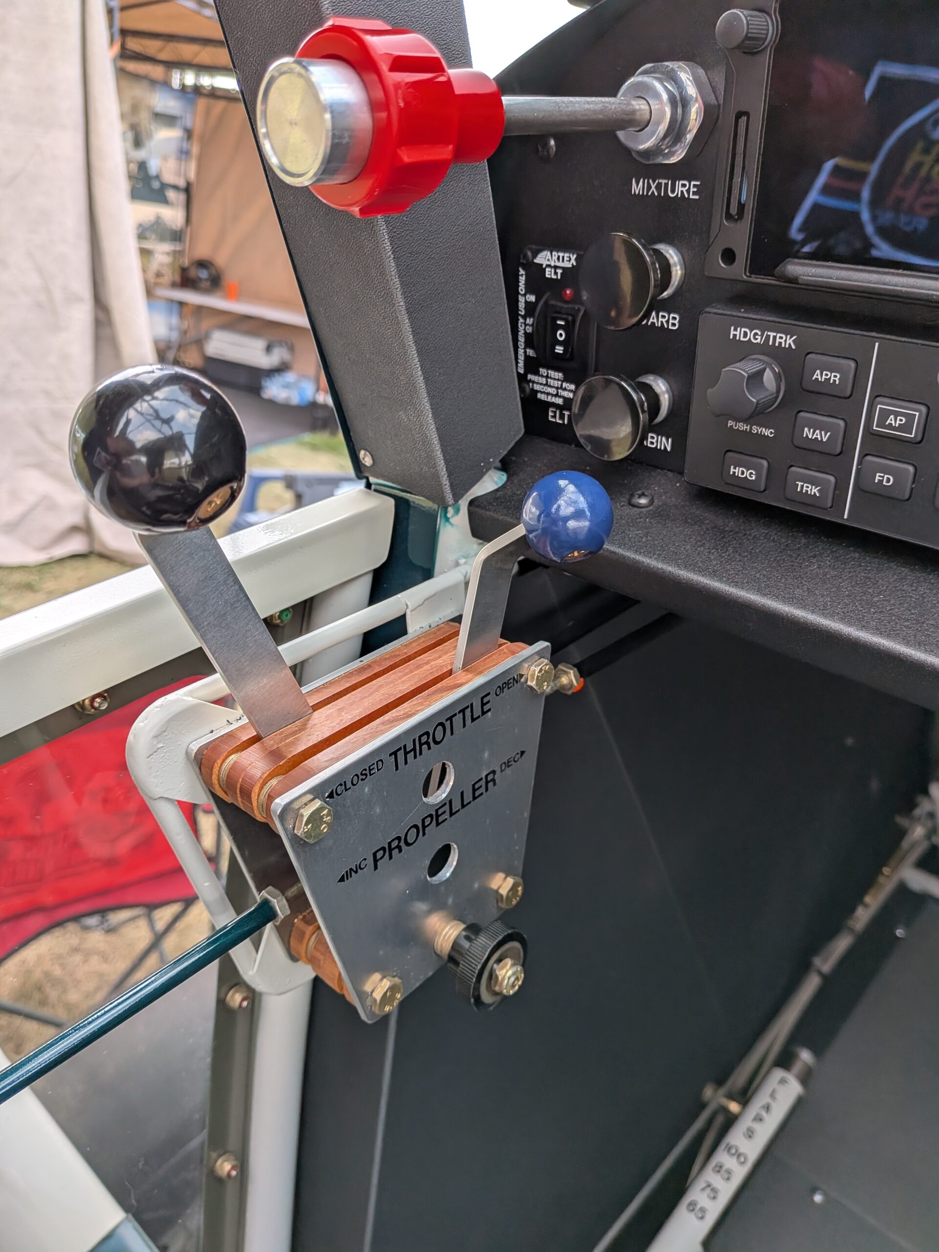
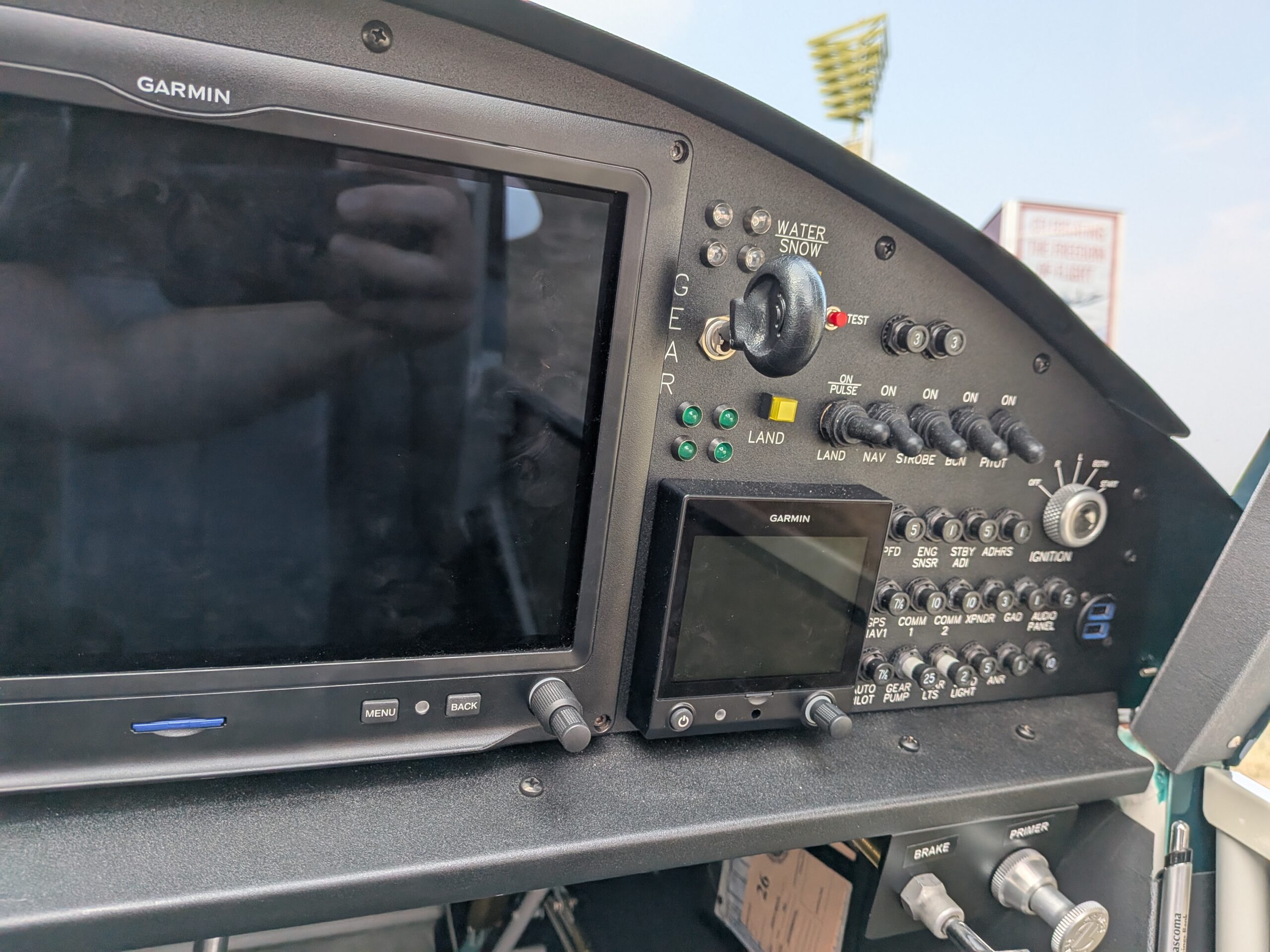
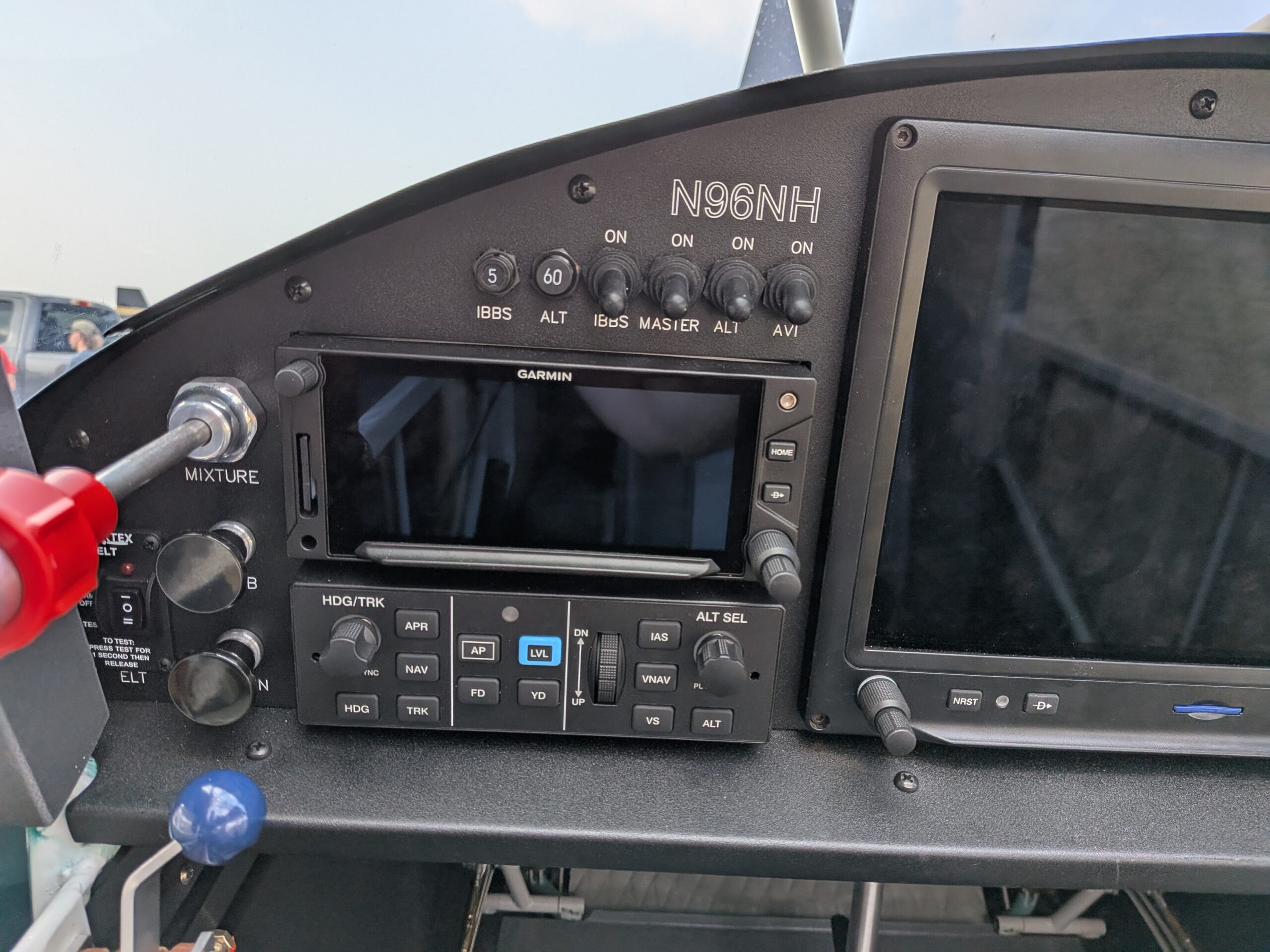
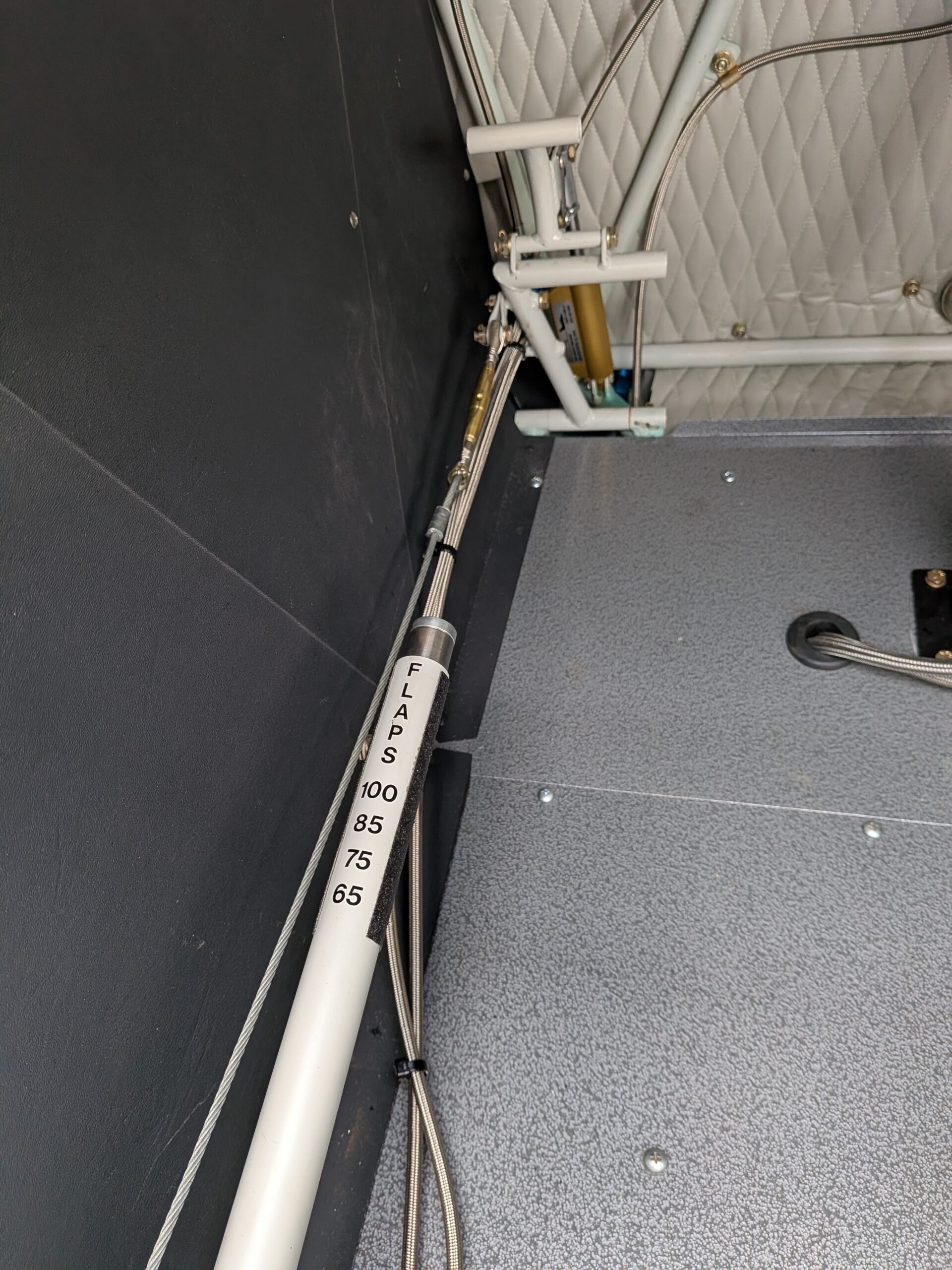
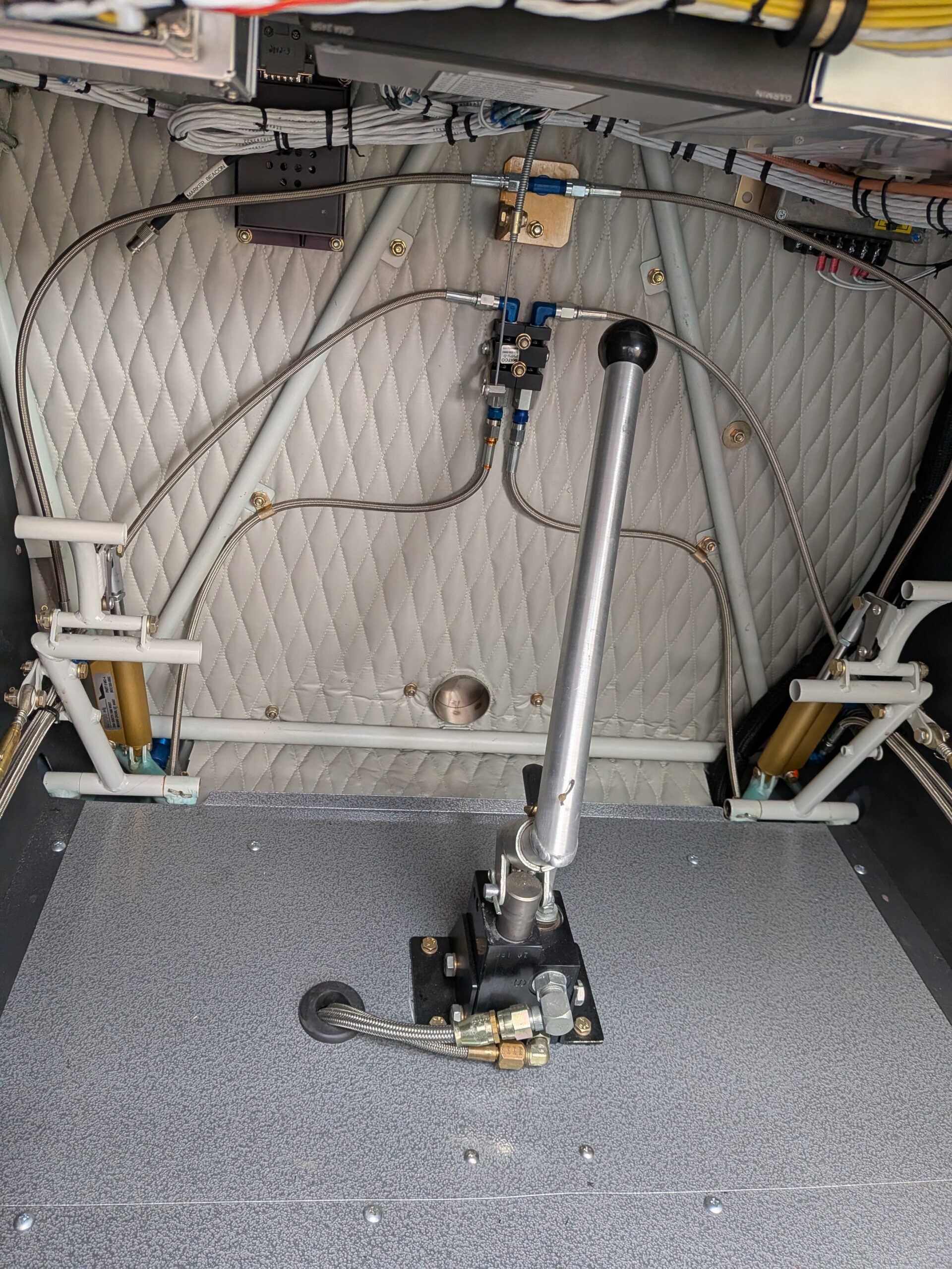
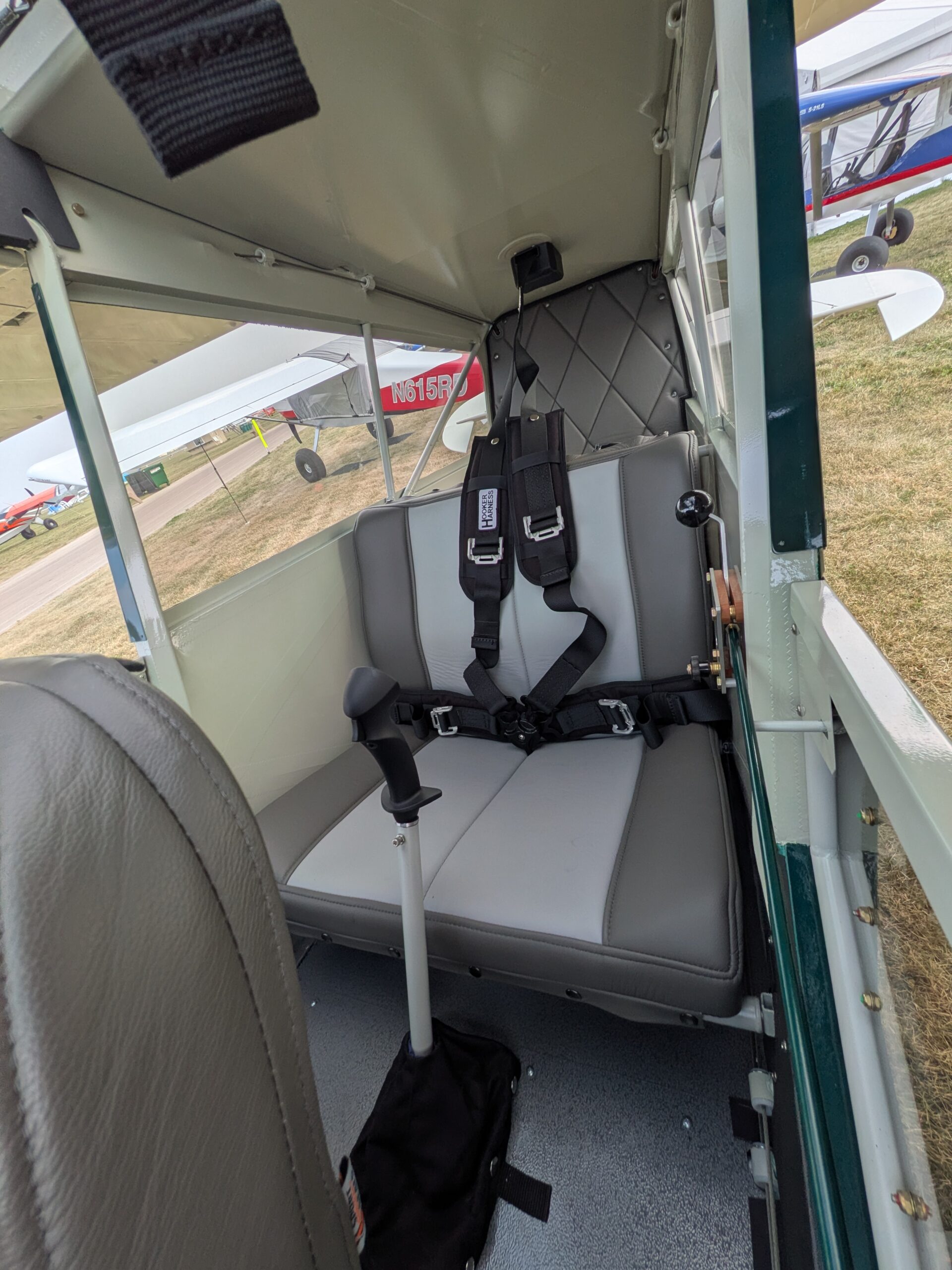
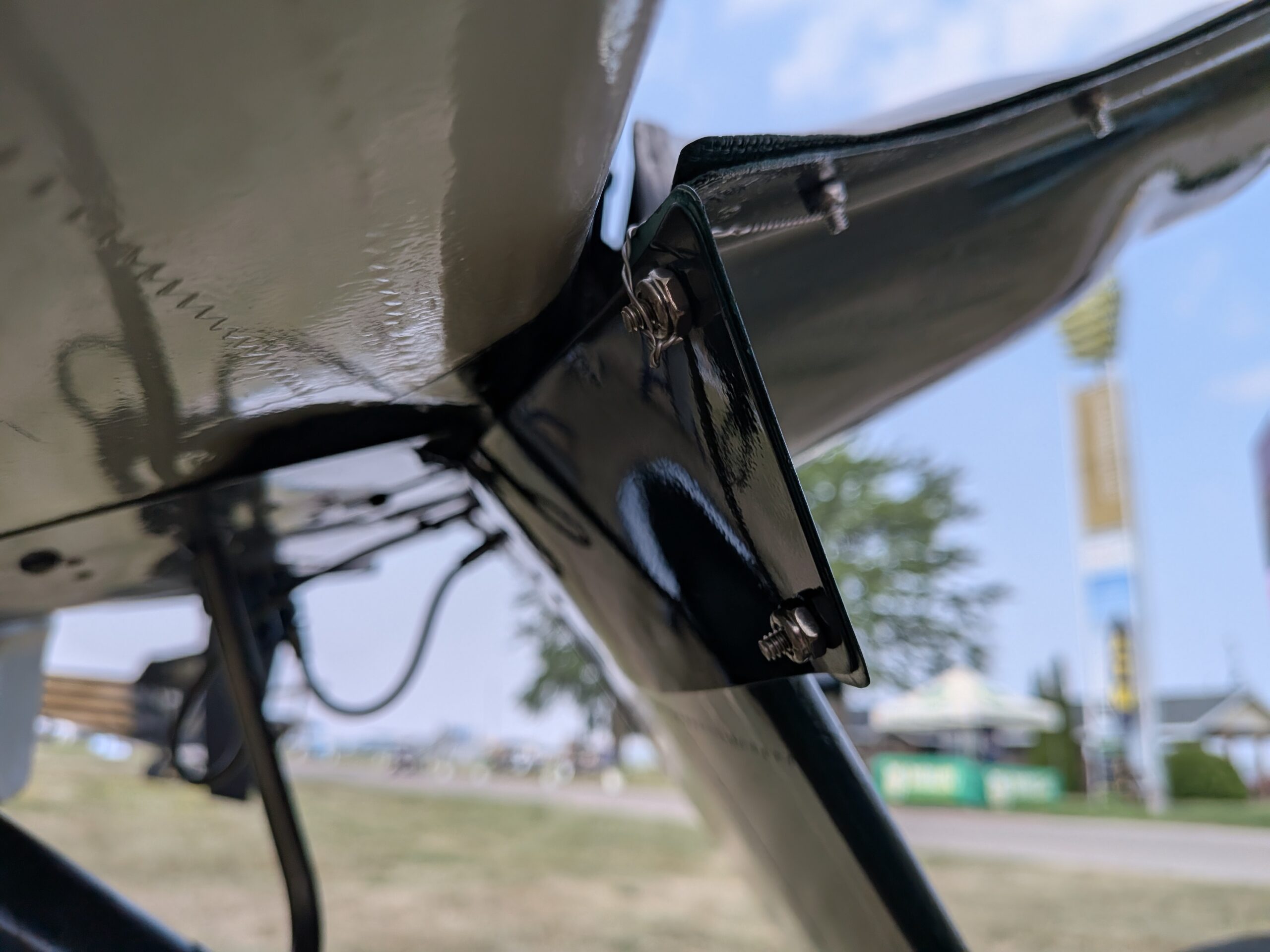
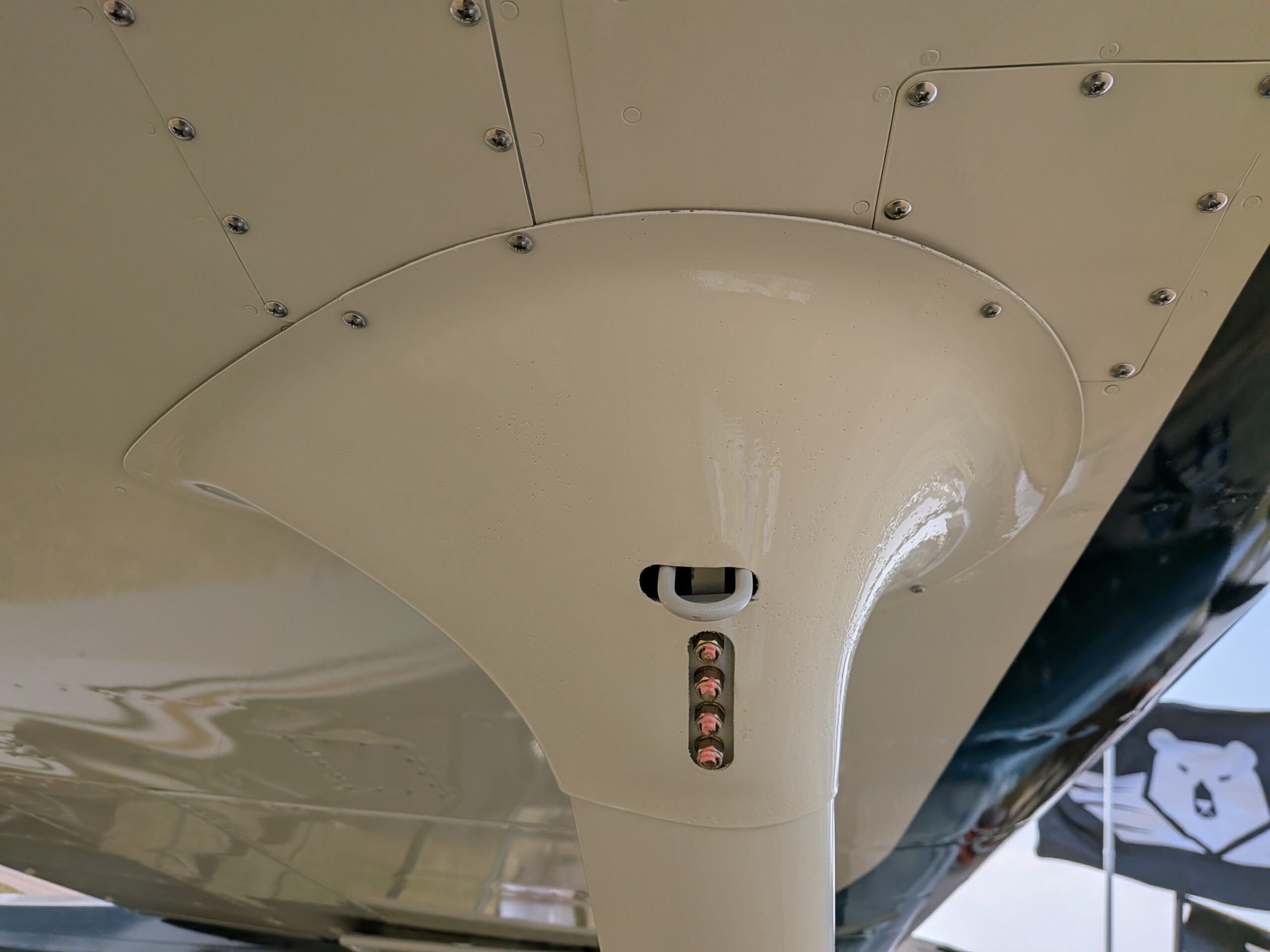
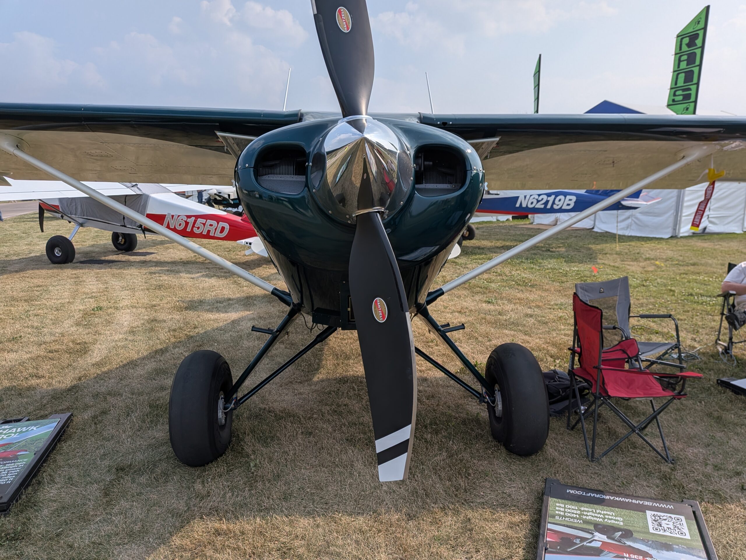
Here are a few details of the float accommodations on this Bearhawk Patrol:
Airventure 2026 Coverage – BH Patrol N96NH Walkaround Photos
Summer Floatplane Trips

Source: 2018 Q4 Beartracks, Heath Sneller
I don’t think anybody has written any trip reports about floatplane flying, so I’ll tell you about a couple small floatplane adventures I had this summer with my boys who are 9 and 11 years old. The first trip was to northern Minnesota. This wasn’t my boys first floatplane trip; last summer we flew down the Mississippi River and camped on an island so they kind of knew what to expect.
I had been planning this one for a while. This was supposed to be an easy trip but you’ll see it got very complicated. It started by looking on Google Earth for lakes in northern MN that did not have cabins on them and were not in Voyageurs National Park or the Boundary Waters. Then I looked on county websites to see if it was public land on the lakes so that we could set up camp. Once this was done I marked the spots in Foreflight.
When the weather looked good we packed up and headed north. The first stop was at Scott’s Seaplane Base (KCDD) on Crane Lake. This is kind of a neat place right on the US/Canada border where you can get gas, snacks, and clear customs. We had food along so we just bought some snacks. After this we took off and headed west to the first lake that I had marked on my map. We circled the lake looking for a place that we could beach the airplane and set up camp, but it was all rocky shoreline so we headed to the next spot on my map. On this lake there looked to be some promising places to camp so we landed. After we landed we taxied around looking at all the shore line and some islands for a decent place to camp, but nothing would work for what we needed, so off to the next lake. This next lake was fairly small but with clear approaches for takeoff and landing, it was 3,000 feet long according to Google Earth, which is more than enough. We circled this lake and there appeared to be a decent place to beach the airplane, so we landed. When we got to within 100ft of the shoreline the airplane stopped because it was so shallow. If I could find a place to camp this wouldn’t be that big of a deal because I had lots of ropes and the wind wasn’t going to pick up that night. I put my boots on and made my way to shore to look for a place to set up camp. I pretty much walked the whole shore line and the brush was so thick that there was no way our tent was going to go up so I walked back to the airplane to discuss the options with the boys. We sat on the floats drank a Sprite, ate a candy bar, and decided on what to do. It was around 5:00 PM and we were not having any luck at finding a place to camp. We did have one option that I hadn’t thought of until right then and that was to go to my sister’s house. She lives on the Rainy River in International Falls. This would kind of be a letdown because we wouldn’t be camping but at least we would have a place to sleep. So we loaded back up and headed to International Falls. Once I found her house we landed on the river and tried to find the house again but almost all of the houses have trees in between them and the river so I couldn’t tell exactly where her house was. After taxiing on the river for a while I decided the best option was to just beach the airplane and walk up to the road to find it. After getting to the shore I had the boys stay by the airplane and I headed up into a yard that a lady was working in and asked which way to my sister’s house. Despite being a stranger who was walking up from an airplane in the river in her back yard she was nice and told me it was just 2 houses down. So I went back down to the river and moved the airplane to my sister’s property and started unloading. As we were unloading my sister and her family showed up to help. Being that their house is below a dam the water level can fluctuate a lot over night so we decided the best option was to keep the airplane on Rainy Lake for the night. My brother in law called a marina that the local float plane guys keep their airplanes at and got clearance for me to keep the airplane there for the night. By now all of our overnight stuff was unloaded so my sister hopped in the airplane with me and we headed over to the marina. By the time we had the airplane tied up my brother in law was there to take us back to the house. Now it was after 8:00 PM and we still hadn’t eaten supper so we ordered a pizza. Despite the fact that we weren’t doing what we set out to do it turned out be a pretty good night since the boys got to play with their cousins and we had a good visit.
The next day my I knew I needed gas since we had done a lot of extra flying so my sister found a gas can in the garage that we could use. We made two trips to the airplane putting in 6 gallons of gas at a time. This would give us enough with reserves to make it to a fuel stop. Once again the boys and I loaded up and took off. I was determined to get some fishing in despite the way things had turned out, so we landed at one of the lakes that we were going to camp at and tried fishing from the floats. It was cold, windy, rainy, and everyone’s patience was worn out from spending 2 days in the airplane, so after one drift we took off and headed east to Tower on Lake Vermillion for gas. Tower (12D) has the nicest facilities for straight floatplanes that I have seen. They have docks and a ramp for floatplanes that are nicer than any for boats. So we topped off the tanks and headed for home.
Even though things didn’t go as planned we still had a good time and a grand adventure. We flew almost 8 hours in two days and gave my sister a new story to tell. The boys were great and after many adventures in the airplane have learned to adapt to whatever happens. When we got home I figured my boys would be leery about taking another floatplane trip but they weren’t and couldn’t wait for the next one.
The next trip was to northwest Ontario in Canada. Last year I took a friend of mine there and we camped and fished on a different lake every night and had a blast. This time I was taking my boys and couldn’t wait.
In parts of Canada they have what’s called the Green Zone. These are areas where nonresidents can fish and hunt but not stay overnight unless you’re staying at a resort or fishing lodge. So with a highlighter I marked these areas on my charts.
Once again we loaded up the airplane with our gear and headed north. The first stop was at Tower (12D) to top off the tanks before crossing into Canada. After we took off from Tower and the boys said they wanted to stop at Scott’s Seaplane Base again and get snacks, it was along the way so why not. Once snacks were purchased it was lunch time so we sat on the dock and ate some sandwiches. Now it was time to head to Sand Point (CJD6), which is where Canadian Customs is. From Scott’s to Sand Point is only a couple miles, so it takes longer to open and close your flight plan with flight service than it does to fly there. Before we left home I had filed all of my customs paperwork with EAPIS so that I wouldn’t have to do it somewhere along the way. This something that you have to do before crossing the border either direction. We pulled up to the dock for customs and got lucky that there weren’t any other airplanes or boats to wait for or maneuver around. The customs agent checked our paperwork and sent us on our way. Sand Point is a neat place to clear customs because it’s on an island and the customs agents pretty much live there for the summer.
Next we were off to see the Log Castle on White Otter Lake. It was a short 40 minute flight from Sand Point and this is one of the nicest lakes in the area with clear water and nice pebble beaches to beach the airplane. The Log Castle is a tourist destination that can only be reached by a canoe or floatplane, it has been featured on many fishing/outdoor shows and on PBS. It is a huge log house that looks like a castle built in the early 1900’s by a bachelor. There are a couple theories as to why he built it but I don’t think anyone knows for sure. The boys were pretty excited to see it and walk around.

Now it was time to find a place to camp so we loaded back up and took off towards the general area where I had planned to camp. Just like on our northern Minnesota trip we landed on several lakes to check out the shore line for places to set up camp, and eventually found a perfect spot. We unloaded all of our gear and set up camp. By this time we were pretty hot so we went for a swim to cool off. Then it was time for supper. I brought brats to cook over a fire, but on our way in I saw some water bombers flying around and I didn’t want them to think that my cooking fire was the beginning of a forest fire and get doused from above, so I came up with an alternate plan. I told the boys I would sacrifice my coffee and boil the brats in the coffee pot over the stove. Once supper was over we did a little fishing and explored the area a little bit.


The next day we had cereal for breakfast and broke camp to head back home. The Canadian Flight Supplement (the Canadian version of AFD) listed Rusty Meyers Seaplane Base as the seaplane base for Fort Frances, which I thought would be a neat place to get gas since I used to watch Beech 18’s on floats there as a kid takeoff and land. When we got there the person working the docks really didn’t want to sell us gas, but after talking to the owner we were able to top off the tanks. Now it was time to clear customs at International Falls. We could have taxied the airplane over but there is a bridge in the way, so we took off, cleared the bridge, set down on the US side, and pulled into the customs dock. The customs agent looked at our passports, asked some questions, and sent us on our way. Next we took off and headed south. Around lunch time we were over Mille Lacs Lake, so we landed, pulled up to the shore, and made sandwiches. Once our stomachs were full it was a short 45 minute flight home. Once again another big adventure was complete, we flew over 10 hours in 2 days, saw some spectacular scenery, did some camping and can’t wait to do it again.
With my set up on floats I almost always fly cross country at 110 mph indicated and burn 10 gph at this speed. This seems to be the spot where the engine stays cool and the pitch attitude isn’t too high or low. When fully loaded I won’t land in a lake smaller than 3,000 ft long. With this rule, when it’s hot and the winds are calm I know I can get off the water with plenty of room to spare. This can be different though for each airplane depending on the engine, prop, and size of floats.


Installing 3000 series Floats
Source: 2016 Q3 Beartracks, Heath Sneller
This summer I mounted straight floats on my airplane. I’ll share my experience in mounting them and maybe cover a few items that haven’t been covered before in previous writings.
A couple summers ago I found a good deal on a nice set of used straight 3000 series floats. They are “Easy Lift Floats” which were made in Canada for experimental airplanes, I believe the company no longer exists but they were in really good shape and had a flat top so a deal was struck.
I had never mounted floats or owned a float plane before so I knew I needed some guidance and called up Curt Malecha who has been flying his Bearhawk for several years on floats. Armed with a camera, tape measure, note book, and level I went and looked at his airplane. Curt was great and let me crawl all over his airplane and answered all my questions.

To start the installation I ordered the aluminum to make the fittings that go from the float struts to the airplane from onlinemetals.com. I then used a table saw with a carbide tipped blade to make the fittings and drilled the bolt holes using a drill press. Next I lifted my airplane using a strap around the engine mount and put a lift under the tail wheel and removed the main landing gear. Then it was time to slide the floats underneath and start bolting the struts on. To get them in the right position I put a chalk line on the floor running from the nose to the tail that was centered in the middle of the airplane. Then I centered the floats left to right on this line. Now was the most critical part of the installation, getting the step of the floats in the right position. To do this I dropped a plumb bob from the center of the airplane CG envelope which I had marked with tape on the bottom of each wing and aligned it with the CG of floats which I had already marked on the floats. After lining this up I slid the floats forward one inch and set the wing angle of attack to 4 degrees and started cutting and drilling the struts to fit from the airplane to the floats. Note: to find the CG of the floats I installed the spreader bars and water rudders and then rolled the floats on a couple pieces of pipe until I found the balance point and then marked where this point was on the floats. The next thing to do was to install the boarding steps which I put where I thought they would work well and are bolted to the float struts.

Now it was time to remove the tail wheel and install a fin on the tail. Curt told me he tried flying without one and wouldn’t do it again, this was all the information I needed so I copied what he did. This included bolting a ¼” x 1” x 30 “ piece of aluminum with Adel clamps to the tail hold grab handles and then bolting the front of the fin to this and the rear of the fin to the tail spring clamp mount. I was unsure about the size of the fin I needed so I used approximately the same size and shape as Curt’s and made one out of ½” marine plywood then primed and painted it to match the airplane. The reason for using wood is that it is easy to change the size and shape and once you get this figured out you can make a permanent lighter one out of tubing and fabric. After this it was time to make and rig the water rudder cables which was fairly straight forward and easy to do.
The final step was the weight and balance. After draining all of the useable fuel and placing some borrowed scales under the floats I was anxious to see what it was. Well it turned out pretty good, my new empty weight is 1,636lbs and the new CG is 11.4”. My CG stayed exactly the same as it is on wheels and I have a useful load on floats of 1,064lbs. (Note that the Max Gross weight can increase to 2700 pounds on floats)
Now came the real test, flying it. It flies just like it did before and handles just fine in the water, I did not have to make any changes to the rigging or to the added fin. It did slow down around 10 mph though. I did not have my float plane rating before this project and was able to do my training and take my check ride in the airplane which was kind of neat. As far as taking off I have found that setting the flaps to 3 notches provides the shortest takeoffs. I tried takeoffs with no flaps and adding flaps after you get on the step and none of which were as short as just setting and leaving in 3 notches from the beginning. I talked to Curt to see what he uses and he too uses this technique. One thing I have found out flying on floats with a Lycoming 0-540 is the CHT’s run 20-30 degrees warmer. I do have some things that I could change with my engine baffles to try and bring them down a little. The big question, how short does it take off? Well short enough, with my family of 4 and almost full tanks on a 85 degree day and little or no wind I can get it off in 15-18 seconds. I live on a small lake that’s around 3,000ft from shore to shore and with the whole family it’s not even remotely an issue. One item that I was unsure about was my prop. It’s a fixed pitch Catto 3 blade that I’ve used on wheels for several years and I thought I would try flying on floats with it before trying something different, so far it has given decent performance and I’m just going to keep using it for both wheels and floats.
This year my goal was to do the initial installation, test it out, and give my family some rides which I did. Next year the goal is to start taking some fishing trips up north. Following Curt Malecha’s advice and techniques I was able to build a float plane that worked right away and one that will provide good performance for years to come.
Ventral Fin for Floats
Source: 2015 Q4 Beartracks, Paul Minelga
First of all, a disclaimer about this article…I AM NOT AN EXPERT!!! I’m just a homebuilder like everyone else, muddling my way through a really big project. One of my criteria for a homebuilt is to put it on floats. That’s the genesis of all this research on the subject and the search for the answer to the somewhat elusive formula: To fin, or not to fin?
What is the definition of a ventral fin as it relates to aircraft? One writes: “A fixed vertical surface on an airplane that extends below the aft end of the fuselage. Ventral fins are used to increase the directional stability of an airplane.” And now the why: “Sometimes they are added after flight testing shows that the original design was inadequate, or after mods that may affect the lateral stability of the airplane (check out the Beech 1900D).
Also, if a landplane is converted to a float plane, the additional forward vertical surface area of the floats requires a balancing vertical surface area aft, either in the form of a ventral fin or vertical stabilizer fins on the horizontal stabilizer.” So now that we know that ventral fins are used on a variety of aircraft, not just float planes. So how does that apply specifically to an airplane on floats?
The size of the fin is really dictated by the frontal area of the floats, control in flight, tail and fuselage surface area, engine size, prop size, etc, etc. According to Al Robinson, his Lycoming O-360 powered Bearhawk on Clamar floats didn’t seem to need a fin.
On the other hand Mike Carriere with the yellow Bearhawk with the monster IO-550 and large floats can barely put enough additional vertical area on the tail on to make it controllable. Mark Scott is an aeronautical engineer by profession and built a beautiful Bearhawk. Here’s what he has to say from some previous emails that I had saved: “As an aerodynamicist I have done some aircraft stability work. The need for additional area on an airplane is a function of prop size and float size. The fact than an O-360 Bearhawk with regular floats needs less ventral fin than an IO-550 on large floats makes sense. By looking at the Bearhawk I’m pretty sure it would benefit from some additional area. The FAA directional stability certification requirement is that an oscillatory decay from a rudder doublet pulse damp down to 1/10th amplitude in seven or less cycles. One could make a survey of float equipped aircraft out there and the size of their ventral fins. A plot could be made to figure out how much ventral fin area would probably work well on the Bearhawk. I think in the end pay an extra pound or two and make a good sized fin that looks right. That is what I am going to do when I put my plane on floats. I recommend making the largest reasonable-looking sized ventral fin. They are not difficult to make. If the directional stability feels really solid you could make another smaller one. Another trick is to install much stiffer rudder return springs. I think there is an STC for Pipers and some Cessnas for this modification.”– Mark Scott
I have been looking at the float installation on the Bearhawk quite a bit and ventral fin attach points were on the list of things to do. The Bearhawk that has flown on Clamar floats apparently has done well. For his installation, it looks like a ventral fin is unnecessary. But, if you choose to go with a different float, a fin may be necessary to compensate for the float size. I plan on EDO 2870s.
I started by looking at similar aircraft: the Aviat Husky and a Maule on floats. Both aircraft had a similar configuration and both had ventral fins. (See pictures) I measured everything, took detailed pictures of EVERYTHING and made a pattern of the fin that was on the Maule. After I got all the data back and did some measurements, I discovered that Bob Barrows had located the front ventral fin attach point at Station G/K, which is over two feet further forward than either of the other production aircraft (January 1999 issue of Beartracks). The ventral fin in the picture is almost five feet in length, tip to tail. If it was built to fit all the way to Station G/K, it would be just over seven feet long! (See the picture to the right for a size comparison)

I called Bob and asked him about that fitting at Station G/K and why that location. He thought the fin could be longer and not as wide, but other than that, no other reason. After explaining what I had for measurements with the Husky and Maule, he agreed that the attach point would be better at Station H. There are two diagonal tubes that meet in the center of Station G where the fin attach point is. I asked him if there would be a need for a similar configuration at Station H/J and he said no. The cross tube was sufficient for any side loads, but if the fin got bumped from underneath, it would be a good idea to put a 3/8ths by .035 tube from the center of the fitting up to the apex of Station H/J to take any vertical load. (See picture) He said you could make the tube go straight into one of the diagonals, or at a bit of an angle where the two meet at the top. This is where the vertical stabilizer attach point is offset by 3/4ths of an inch. Either way would be ok.
I was ready to make the ventral fin when I came across a fin from a 1978 Maule M-5 on Craigslist. I jumped at the chance to have an actual production fin to look at as opposed to just making an semi-educated guess as to its construction. I was surprised after I stripped off the fabric to see how much structure there was to the fin. Originally I thought it was just a couple of tubes with some brackets at the top, but it was quite a bit more involved with four different sizes of tubing. Most of the photos of the fin and my construction is found on my kitlog web site (www.mykitlog.com/yeeeha), so I won’t repeat it here. But for a few details that aren’t apparent, I did a few changes from the Maule design. On the front mount I made it like the Husky, utilizing two AN-4 bolts instead of four. I used .062 for making the front and rear fittings on the fin. On the fuselage end of things I did things a bit different than what was in the January 1999 issue of Beartracks. I made my mount at Station J out of .071 (what I had) and made it to mirror the size of the mount pad on the fin, which is quite a bit more substantial than Bob’s original idea. I do plan on adding the 3/8ths .035 tube, but I have to buy some first…I ran out!
To summarize: For my build, two-blade Hartzell prop in front of an IO-540 C4B5 and using EDO 2870 floats, I decided that a ventral fin will be necessary and I now have one that will certainly do the job. Hope this all makes some sense and good luck on your builds!
Bob’s Bolt-on Float Fittings
Source: 2001 Beartracks, Bob Barrows
For those of you who do not want to weld permanent fittings on your fuselage for a float system, Bob has designed this bolt-on system.
It may be a bit difficult to see the faint outline of the side bushing in the photo. The bottom fitting is used for the cargo tie down ring or to bolt a rear seat in place when you utilize the Utility Door System.
The side bushing can also be used to attach a seat belt system for the rear seat if you decide to install one.
Float Plane Extra Dorsal Fin Instructions
Source: 1999 Beartracks, Bob Barrows
Extra vertical fin area will most likely be needed if the plane is to be equipped with floats. A fitting can be welded in place at station G-K in conjunction with the tail spring mount at the tail post. These two mounting locations will allow the dorsal fin to be bolted on under the fuselage.
1998 Beartracks Mailbag, Q&A with Bob Barrows
Source: 1998 Beartracks, Bob Barrows
Dear Bob,
This is a formal invitation to come visit us in this area on your trip to Alaska. It is sure to be an exciting adventure and I am envious of you actually planning it. I often talk about going to see my old flying instructor (Ray Krumrey) in Old Harbor, Kodiak Island but haven’t got there yet. It is one of my flights of fancy to fly there in the Bearhawk and do a big impression on him. Ray is a great guy and we became good friends as a result of flying.
David Giles (#222) wants to meet you. He is an SDA Minister who flies an RV-6 he built and is barely started on the Bearhawk his son and he are doing. He is a really nice fellow – one of your fellow Countrymen originally – and he visits me fairly often. I’m sure that there are others who would like to meet you too. Another reason for coming is that you will be right on course for the “Rocky Mountain Trench” which will take you right to your destinations in Alaska. It will be a comfort to you to know that you will be flying over a lot of paved road (emergency landing strip). Be advised that GPS is definitely a good idea as there are very few other Nav aids in this North Country once you get 300 miles North of the Border. I haven’t actually been over but I am told it is great!
Progress on the Bearhawk is slow and steady. My Son has already dubbed it with the moniker “Times Two” since I have made so many things twice! I keep telling him that those were “test pieces”! However, the fuselage is largely done and I am working on the little bits and pieces necessary before I move it off the reference plane of the dead level and flat workbench I built from three 16ft TGI floor truss crops. Used 4×4 legs with adjustment bolts in bottoms. Covered top with 4×8 plywood with one foot overhang. Using other shipping plywood, I made shelves between the truss ledges. This works well as they slide out and is a handy place to store pieces of tube right under the bench top. Simple, strong and flat and it can be disassembled as I put the legs on with lag bolts and left about 4″ edge overhang!
Have all the wing pieces built but have not done any skinning of them. I got tired of pounding aluminum and switched to building the fuselage. This winter I hope to make the tanks and a lot of the hardware pieces like seats, controls, levers and such. The main idea for me was to have a project to keep me out of mischief! It has worked but I have also derived a great deal of enjoyment and satisfaction from building (to this point).
Bill and his wife spend their winters in Arizona. He got me onto this design of yours and has been a great resource with all his experience. He and another of his friends are building an RV-6 each. He likes to get upside down once in a while, he says! He sold his Stearman. The Airline driver who bought it had to get some old timer to fly it back East because he couldn’t handle it. After getting it home, the nerd wrecked it within a week! Wheel landed on wet grass area and hit some puddles of water. End of story! $50,000 later … ??? All the best,
Rod Dressell – *190 – Creston, B.C.
Dear Bob,
Do we need to consider increasing the vertical stabilizer/rudder size, or add a dorsal (ventral) fin for use with floats?
Thanks,
Bob Thomasson – #280 – Santa Rosa, CA
Bob,
The rudder will not have to be altered in size to accommodate floats. The vertical fin area may have to be increased to counter the side area of the floats. A dorsal fin bolted to the bottom of the fuselage will accomplish this. Weld in a bushing for a 5/16″ bolt at station G-K and use the tail spring attach fitting to bolt on the dorsal fin. I am not sure as to how much fin area is needed – you will need to experiment, and talk to other float pilots. Bob
Bob,
Keep up the good work, your newsletter is invaluable! … Still working on the wings.
Thanks
Brad Young – #229 – Spearfish, SD
Dear Bob,
Just a reminder that we wanted to be put on the list as one of those who would order struts from you. Fritz and I put the wings on last weekend. We had the fuselage setting sideways in my garage with one wing in and one wing outside of the garage. The door was covered with plastic sheet so we could heat the place. It took a day or so to get things squared up and the wings are off now and tucked away in their rack until next spring when we can paint them.
We hope to be done by the first of April ’98 if things go well.
Tom Lee – *98 – Winona, MN
Dear Bob,
Well, I’ve had your Bearhawk in the back of my mind since I read the Sport Aviation article 2 years ago. I poked around the airplane a OSH last year but never got to meet you or talk to you about it.
My RV-6 is almost rebuilt – after being run over by a Chevy, believe it or not – and I am contemplating a project where I can learn some new skills.
I work for Dick VanGrunsven and can get almost all the materials needed very reasonably along with access to all the metal forming equipment you could ever want.
So – what I’m thinking about is a minimal, light airplane – but with a battery and starter, hooked to the lightest six cylinder engine I can find. Say an 0-470? Do you think this is practical for a guy with minimal welding skills but good teachers?
Enclosed is a check for your flyer & – I hope – a collection of past newsletters. I write the one for Van’s, so I like to read other peoples! Addresses of Western OR or WA builders would be appreciated too. Thanks.
Ken Scutt – Hillsboro, OR
Ken,
Thank you for your letter and the request for information on the Bearhawk. It is interesting to hear that you work for Van’s Aircraft and write his newsletter.
Many builders of the Bearhawk are doing this airplane as a first time project and learning the skills as needed, from knowledgeable EAA members.
Please find enclosed a data sheet, photo, a selection of newsletters and a list of builders in your area.
Thank You – BOB
Dear Mr. R. Barrows,
I have received the drawings for the Bearhawk: The drawings are beautiful!
For your super excellent work – I send my graduation!
Yours Faithfully,
#209 Stefan Kjorcev-#308-Oberglatt SWITZERLAND
Tim Neal #209 sent in this photo of his project.
A few questions as my fuselage is well on and I will need some answers to keep going.
1) For the rear door modification – you specify .032 alloy, would .025 be too light?
2) Will you be supplying a detail of the main doors in the newsletter?
3) What weight of alloy do you use for engine cowling – .020 or .025?
4) Routing of fuel lines from tanks and do you run separate line from the front and rear draw off points on tank and join to one in cabin or how do you do it?
5) Your method of attaching plastic sight tubes for fuel to alloy tank tubing?
6) Have you a fore and aft adjustable for front seats to seat long and short legs?
7) Some friends of mine at Oshkosh talked to you and took some good photos, a question on your exhaust system, by the photo: you appear to have 4 separate pipes, are they straight out and what is the noise like?
8) The trim system on your drawing #22; Do you need a friction disk or is there enough friction in the system? Is the trim chain a 1/4″ with a 12 tooth sprocket?
9) Positioning of wing attachment fittings on fuselage, the 32″ dimension is OK but the parallel dimension for both sides in relation to the spar fittings and lining everything up, my spar fittings are pilot drilled 3/16″, presumably the fuselage fittings should only be pilot drilled at this stage? These wings are quiet large compared to my Tailwind, so will you be giving a rundown on the fitting, lining up and setting dihedral, drilling and reaming holes to size, etc.?
10) Lift strut fittings, I have made up the wing end channel fittings, the double joggle in the fuselage end is somewhat more complex. What was your method of shaping? Also do you square cut the ends of the struts or angle cut to angle of wing and fuselage?
11) 1 know from a previous comment that you prefer a control stick and my Tailwind has a stick but I really want to have a yoke system with the Bearhawk. Much easier for females with a dress on and the floor remains relatively free of obstruction. Could I copy something?
12) Finally, the need for a fixed step up into the cabin like many aircraft have, my wife is not that tall.
Regards,
Ray Thurston – #5 – Blenheim NEW ZEALAND
Ray,
Good to hear from you again.
Regarding your questions:
1: .025 should be OK. 032 is better for the wear and tear resistance.
2: We will cover door construction in a upcoming issue of Bear-Tracks.
3: .025 is used. You may use .032 for the top.
4: The tubing is joined below lower front door frame with T section. (Upcoming newsletter)
5: Below is a sketch of what I recommend:

6: Yes – the same as a Piper Tri-Pacer. This system is nice in that as the seat moves forward it also rises lifting the shorter pilot up to see over the instrument panel, as it goes back the seat lowers giving the taller pilot more headroom.
7: I have 4 straight stacks out of the bottom of the cowling. I am told that they are loud but not unpleasant. I do wear earplugs.
8: No there is enough friction in the system.
9: See here.
10: I’ll cover the correct method for bending the end fittings in the next newsletter. Cut the strut ends square.
11: We do not plan to design such a system but you could copy the Tri-Pacer or a Cessna design.
12: A step is a builders option – check as designed on other tube fuselage aircraft.
Thanks for your letter and send us some photos of your project! ~ BOB
Bob,
I want to thank you again for your time and sharing techniques. I made another set of fluting pliers and they make a nicer crimp. I am also doing my rib lightning hole flanges a lot better, no warped ribs.
The idea of putting tape on the fluting pliers to keep from marking the aluminum really works. Thanks.
J.T. Newbegin – #284 – McAlpin, FL
Hi Bob & Mike,
Just got your newsletter, sounds like a lot of great activity with the builders. It also looks like you are getting close with Proto II.
I have enclosed a check for $250 for a pair of wing struts. I will be looking forward to getting them.
BEARHAWK 075 has fabric on it now. I am taping at this time and hope to have everything in silver in a couple of weeks.
The engine has not been installed yet, it will be a Ford Dura Tech 24 Valve 3.0 V6. I am converting the engine myself and have had to do a lot of searching to find an ignition/fuel injection computer system that I felt comfortable with. The original Ford system has too many extra input requirements and no adequate wiring diagrams.
After the engine is roughed in and the fuselage is on the gear I will send you some photos.
Have a great day!
Tom Yeomans – 075 – Richland, MI
Tom,
Sounds like you have made quite a bit of progress on your project. A lot of the builders may have an interest in more information about your Ford conversion. Keep us updated. ~ Mike
Chuck Frasier called the shop a few weeks back and had a question about the tail feathers. He was fitting up the elevator and found that the trim tab arm is rubbing the T-14 spar tubes on the horizontal stabilizer and the elevator.
To fix this you put a 10° – 15° bend in the trim tab arm under the elevator T-14 tube. You should clear the spars by a bit more than 1/4″.
Reference drawing #20.
Enclosed is a check for one pair of struts. I have finished a full review of the plans and worked out a material list. I bought all the .025 aluminum I’ll need and I am accumulating the other material.
Still trying to get my garage finished and other projects I had already started so I can start pounding out ribs. Is there enough strength requirement for using the 1/2″ X 1/2″ rib attach angles or can I make more than one forming block and bend up the end of ribs for attachment? I would rather make more forming blocks and save some weight unless the attach angles are required.
I have not seen in the October Sport Aviation article or in Bear-Tracks or in the plans any information on testing. Has the plane been flutter tested? Has the plane gone through flight testing such as dives to Vne, stalls at both ends of the envelope, light weight to gross?
Thanks for the help. Would sure like to see N6890R if you stop near Seattle on your way to Alaska this year. A visit to the Arlington fly-in would sure be nice for the west coast builders who can’t make it to Oshkosh but would like to see the BEARHAWK!
Wayne Hallburg – 266 – Centralia, WA
Wayne,
Thank you for the strut order – we will be shipping the struts (hopefully) before you read this. About your questions: Yes you can eliminate the angles if you wish but you must take into account the varying widths of the spars at different locations. The flutter testing was done during dives to Vne speed at 180 mph and stalls have been done at 1500 lb and 2400 lb gross with no unusual characteristics shown.
We are planning on attending the Arlington fly-in this year and hope to see you there. -Bob
Bob responds to a fax from Ray Thurston :
Ray,
In reference to your fax of 01/16/98 about the flap control assembly drawing #28: In checking the fit up on the BEARHAWK now under construction in my shop I did use the arm length as shown on drawing #28 but I offset it as shown below. In addition I moved the shock strut attach fitting (see drawing #24) up as high as I could and still have room for the rod ends HMX-76. This all gave me the clearance that I needed. ~Bob
Dear Bob,
Enclosed is a check for a pair of wing struts. I am also enclosing a photo for the newsletter. It is a picture of a die, made by Doug Jasper, for bending the flat plate pieces for the wing hardware.
It worked quite well and I think it is obvious how it works. He spaced the bars so that one side will bend .063 and the other side .080. I filed a radius on the edge of the male die, which is 3/4″ key stock, so one side does .063 and the other .080.
I just finished my steel wing hardware. I brought my flap and aileron mechanism to my EAA Chapter meeting last night and everyone commented on how nice they looked. Even had one person praise you for the engineering and how smoothly the mechanisms worked. I am now finally beginning to assemble my first wing. Slow but sure.
Pat Fagan – #232 – Pearblossorn CA
Dear Bob,
I am confused about the turnbuckles for the elevator where connecting to the bellcrank.
Drawing #26 says AN 135-32S Turnbuckle. I just ordered as specified and find on arrival when I was doing a trial fit that the pin eye is .25″ and yet the bellcrank says 3/16″.
The Cable eye likewise seems larger than required at .281″.
All parts are stamped and the turnbuckle is definitely AN135-32S. Would AN135-16S be more appropriate? Could you let me know?
Ray Thurston – #005 – New Zealand
Ray,
The AN 135-32S as called for in the plans is correct. You will need to make a bushing from 1/4 ” x .028 4130 tube, and use (2) AN960-416 washers as shown. ~Bob
While at Sun N’ Fun several builders brought pictures of their progress. Below is a photo of Larry Williams #184 project. Larry is using a Continental 0-470 for power. ~Bob
Bob,
I received the wing struts Saturday and the plans for the struts a few days later. Thank you. I received the cap strip material I ordered from Wicks last week and I bought some rivets to practice with over at the fly-in and flea market at Hampton Airfield on the coast of New Hampshire. I am a little nervous about starting the spars but I am sure that it will all go fine.
A friend of mine has landing gear and the gear shock struts that go on a 1947 108-2 and we were wondering if it would work on the Bearhawk. If so is it as strong as your design. What are your thoughts.
Sonny Cilley – #234 – Royalton, VT
Sonny,
I am sure that your spars will come out fine. It is just a matter of following the directions on the plans and in the newsletters.
The 108-2 landing gear system that you have is strong enough for the Bearhawk – but doing the engineering work to install them would be quite involved and time consuming. The time spent adapting the Bearhawk to accept the Stintson landing gear would be greater that just building the gear shown in the drawings. ~Bob
Bob & Mike,
It was great meeting both of you at Palmer, Alaska and I immediately dived into the plans and newsletters. Wish I had had the chance to study before going to Palmer but that is life in the frozen North.
As stated at Palmer, here is my check for a set of struts and drawings. I also want your wing construction and photo log, which will answer many procedural questions, I’m sure. May as well get the Disogrin ring set as I don’t want any delays for parts. While I have not yet ordered my 4130 and Aluminum, I have sent for all the books and catalogs recommended, made up a material list, made the wing rib form and acquired jig material (table) and a good shop to build in. All this since getting back from Alaska on August 12th. Being retired has its advantages.
I was in Alaska for about two months installing the water wheel power project for my friend. We are still evaluating the project, though the initial data
is quite favorable and slightly exceeds expectations after some modifications.
Hope all is well in Fincastle, do you think you might do Arlington again next year? I would like to have a list of Washington builders list and when available. In the meantime I will be attending the local EAA chapter meetings which I understand is loaded with talent.
Is there a drawing for the float hard points?
Just so I don’t miss any bets, please let me know your pricing for an 0-360. Thanks and looking forward to building.
Jack Piggott – #347 – Sequin, WA
Jack,
Thanks for the photos and letter. The struts have been mailed out along with the drawings and the o-ring seal kit. You should unwrap and oil down the struts when you receive them before putting them in storage. Mike has sent you a photo log that you should receive soon.
It sounds like you have really been chugging along on your project. Keep up a good head of steam because it is a long haul.
Regarding the float attach points, see the 1996 issue for rear float attach location, and use the front landing gear fitting for the forward attachment point. The fitting at the rear can be made just like the landing gear fitting if you like. We will work more with you on this area as needed. Do you have any idea what kind of floats you will be using? ~Bob
Mr Barrows,
Just a letter of introduction that is long over-due. I recently purchased plans s/n 188 from Mr Serge Valin the package also included the photo log and newsletters to October 1996. Enclosed is a check for all the back issue that I am missing and a subscription for 1999.
With any luck this winter will see me pounding out ribs. If there are any builders that are close to Detroit, I have access to a 10′ shear and brake for spars.
Mark Deacon- *188 – Brownstown, MI 734/789-1196
Mark
Your newsletters are on the way. I’ve included your phone number for builders in your area that may want to get in touch with you regarding the 10′ shear and brake. ~Bob
Float Modifications
Source: 1996 Beartracks
These tubing sizes are to be used if the aircraft is to be put on floats.
Design of attachment fittings to be welded in place at “E” will be discussed in upcoming newsletters.
Curt Malecha’s Bearhawk
Source: 2012 Q3 Beartracks, Mark Phillips
Few things are better than a summer day in Minnesota when the temperature is about 80 and there are just a few clouds in the sky. You add a beautiful Bearhawk and you have a perfect day. As a scratch builder of Bearhawk plans #1228 you can imagine how excited I am to see other projects and see how other people are making these crafted pieces fit together. When you get the chance to look at a completed aircraft you jump at that opportunity and take a look. I’m sure everybody that is building an airplane has looked to see how many of that type are in the area where they live. I found out about a flying Bearhawk about 100 miles from my house so I started to do some research. It wasn’t really all that hard, I knew the owners name, Curt Malecha, and looked him up and left a message. The next day he called back and we started making plans on when we could meet to get some pictures taken.
We set up a date about a week in the future and hoped the weather would cooperate with our plans. The day before our planned day a quick look at the forecasts showed that things looked good. Scattered clouds and light wind all spelled good news. I shoot out of a C172K, only the left side window opens so I asked Chuck Schmidt to fly while I would be shooting. I called Curt and Chuck to tell them we were good to go the following morning. Mother Nature was not going to let me off that easy. I woke to fog outside and 1/4sm visibilities, but a quick check on the computer of forecasts and currents made me feel at ease as I was pretty sure this fog was going to lift early. I feel confident in my ability to read into the forecasts and in my knowledge of weather. On the way out to the airport a quick call to Laurie at the Princeton FSS confirmed what I suspected. A very nice, hour long flight and we were there.
As I taxied up to the ramp in Fergus Falls there it was sitting all alone on the ramp. The sun was shining on the airplane and with no one around; I couldn’t pull up and shut down quick enough. We agreed to meet in the FBO, but I could not resist, I had to go over and take a look at the first Bearhawk (that I know of) I have seen. Curt came out to greet us. He understood that I had to take a look. We went inside the FBO and started to go over a time line for what we wanted to get done. Curt told us that some of the local pilots got together on Fridays and made lunch. Today they were doing pork chops on the grill and baked potatoes, and we were welcome for lunch. This day just kept getting better and better.
Curt taxied the Bearhawk out onto the grass (where it is at home) so I could start to get some photos; he then went to tend to the chops. The Fergus Falls municipal airport has great facilities and the two runways were in great shape, and all the taxiways and ramps were in tip top condition as well. Over lunch I learned of two other homebuilts finished last year based at the field, a Kitfox owned by Lawrence Deal and a RV10 by Jay Wik.
Quick Build kit #19 arrived at Curt’s business, a rental store, in 2003 and there the project began. With Bearhawk plans #672 it should be easy right? Not so fast. As happens, life took over and Curt and his wife Lisa built a new house, sold his business, and started another business, the FBO. During this time they also adopted 11 children to bring the total to 13. The aircraft’s registration N132CL was chosen for that because God gave 13 kids to (2) Curt and Lisa.
Curt calls it a slow build kit. It was a total of 2500 hours building and another 2500 hours of research to get everything completed. After eight and a half years of anticipating and dreaming, on December 28, 2011 in the morning Curt had an airworthiness certificate in his hand. After a lunch, Curt could not wait any longer and conducted the first flight by 1:00.
The first flight went very well, 1.1 hours near the home airport FFM. The reason Curt chose the Bearhawk was because he wanted a capable float plane, after the first flight he knew he made a great decision. Each test flight was recorded in an aircraft test log book noting and recording EGT, CHT, RPM, MP, fuel flow, altitude and outside air temperature. The only issues were door leaks and a yaw. A rudder trim tab fixed the yaw. The other problem was fixed with different seals. All forty hours were flown with no other issues.
The plane was made to eventually be on floats and by the end of summer may never see wheels again. With this in mind, aux fuel tanks for long range fishing trips, and float attach fittings were installed. The custom sea plane doors were designed to be simple and easy to latch with lots of visibility. The doors are hinged at the top so a person could easily get out and walk forward on the float when approaching docks. The biggest obstacle in making the door was the strut. Shortening the door and raising the door jamb fixed that problem. After installing a gas lift strut the doors were perfect. EDO 2870 floats are getting redone as this is being written.
The aircraft is powered by a Lycoming O-540 producing 235 hp. A McCauley 8452 fixed pitch prop was installed and the verdict is still out if that was a good decision. It runs smoother than most 540s because of a LSE plasma II ignition and tuned SS exhaust. An ACS 2002 EMS was a good choice and they have been a great company to work with. A dual battery system works well for remote fishing.
Several years ago Curt was at Oshkosh looking at avionics. He found what he thought would be the perfect setup. He bought a Blue Mountain EFIS, who would have known we would see such advancement in avionics. He admits he may have bought a little prematurely. Custom leather rounds out the interior.
The exterior was done with Stewart Systems paint on the fabric and urethane on the metal parts. The paint and color scheme were picked by Curt’s daughter Genevieve. Because of her talent, everybody can appreciate how great it looks, and how well the colors look together. He said it was fantastic to have her help in the building process and lots of fun.
After lunch the plan was for a quick twenty-thirty minute flight to get about 300 air to air pictures. This was going to be simple, right? Everything worked great until Curt peeled off to do a 360 degree turn to get some banking shots. Who would think that a two toned brown and green C172 would be hard to see over forests and marshland. After 10 minutes of calling off landmarks to each other we got back in formation. We flew back towards the airport while I took more pictures. There was just enough time left in the day for one more quick flight. I was thrilled to get a chance to fly the plane, it flew as well as it looked.
The airplane would not look or perform as well as it does without the help of Kevin Cary. Kevin was instrumental in so many ways that without his help and knowledge there is no way that this Bearhawk would be flying let alone looking like a complete aircraft. Friends Craig Johnson and Lawrence Deal were always willing to help and provide wisdom and free advice. This was the first airplane project Curt built. It is said that it takes 10 houses before you build the perfect one. This may not apply to aircraft because there are few things Curt would do differently. Overall he is more than pleased with the almost perfect Bearhawk.