Engineering Notice Concerning Aileron Pulley Selection

Source: 2000 Beartracks, Bob Barrows

Reference Drawing # 14 – The aileron cable pulley can be changed from a AN210-4A to the 1/2″ smaller O.D. MS20220-2 if needed to allow the aileron cable to better line up with the wing strut.

If you use the MS20220-2 pulley you will need to bush its I.D. to 1/4″ or use a 5/16″ bolt and drill out the pulley bracket.

Inspect the line up of the aileron cable to the pulley, if not close to centered the bracket may need to be adjusted a little for proper line up.

Continue reading

Engineering Notice Concerning Flap and Aileron Nose Skin Rivet Size (395 and Below)

Source: 1999 Beartracks, Bob Barrows

Reference plans number 395 and below, Drawings #9 and #10. The 3/32″ stainless steel pull rivets holding the nose skins to the nose ribs have been changed to 1/8″ aluminum pull rivets. The cost and availability of 3/32″ S.S. rivets has become a problem. If you have already assembled the ailerons and flaps with the S.S. you can leave them in, they do a good job.
Continue reading

Filling the Aileron Balance Tube with Lead Shot and Epoxy

Source: 1999 Beartracks, Bob Barrows

An easier and safer method of filling the 3/4 x .035 aluminum tube with lead is to use lead shot. You can find lead shot at K-Mart, Wal-Mart or a shooters supply store. Tape one end of the tube shut with masking or duct tape. Mix the lead shot with epoxy or a slow setting polyester resin and pour the mix into the tube. Set the tube out of the way in an upright position until the resin hardens.

About 5 pounds of shot will be needed for each aileron.

I used this method on the latest set of ailerons I built and found it much easier than pouring and working with hot lead. It does cost more but it might be worth the investment if you are leery about handling molten lead. Don’t epoxy the tubes to your kitchen floor – make sure the tape seal is tight!

1998 Inboard Flap Lever Engineering Notice (280 and below)

Source: 1998 Beartracks, Bob Barrows

Reference drawings #12 and #14 for plans serial numbers 280 or below.

Inboard Flap Lever

The inboard flap lever arm was shortened from 4-1/8″ to 4″ for clearance with the aileron cable. If you have completed this assembly you may remove up to 1/16″ from the tip of the flap lever arm for clearance. Continue reading

Flap and Aileron Riveting

Source: 1997 Beartracks, Bob Barrows

The skip riveting method can and should be used during the attachment of the nose skins on the ailerons and flaps. Using this method will help reduce the tendency of the control surfaces to warp and twist as the riveting is done.

With ribs and trailing edge riveted in place (check trailing edge position to match with wing).

Install nose skin and secure with clecos use skip riveting method on both top and bottom of the spar, check aileron or flap for NO twist before installing the rest of the rivets.

1997 Beartracks Mailbag, Q&A with Bob

Source: 1997 Beartracks, Bob Barrows

The mailbag has been stuffed the last few months. A lot of good progress has been made by several builders who want to pass along information. A lot of questions about different powerplants are being raised about everything from Fords to Chevys to turbines and everything in between.

Bob,

I’ve been thinking of using a Turbo-Prop engine in my BEARHAWK. Turbomach T62 t401c1 (Solar) of 225 SHP available new surplus @$4750. However I need to find a matching gear reduction unit (PRSU) for approximately 2.5 or 3 to 1 reduction and constant speed prop unit. I haven’t been able to work out the details yet but I will make engine and cost comparisons this winter and work on the installation problems too.

I am somewhat familiar with turbine engine conversions as I assisted in a COX TURBINE OTTER conversion in Seattle, WA and have 30 years experience as an aeronautical engineer with Boeing.

My hope is that a turbine combination will result in lowest empty weight for maximum performance at similar cost compared to the Franklin 220 and Lycoming choices.

Paul Hubble – #126 – Deer Park, WA

A letter off the net –

I finished building a Murphy rebel in April of this year. I now have 60 hours on it and it flies real nice. Out here in the west (Barstow, CA) density altitude is a problem. I decided to build the BEARHAWK to get a little more room and also a larger engine. Right now I am leaning toward an auto conversion by Belted Air Power, of Las Vegas. They use brand new Chevy V6 engines and sell a complete firewall forward package for the RV-6 for $8000. We looked at it at Copperstate and liked it. It puts out 225 hp and uses a belt drive reduction. Bob Barrows was right in one of the newsletters when he said not to worry about the engine until it is necessary. I learned that from the Rebel, I rushed into buying a Lycoming O-235 and now everyone is using O-320’s.

I have started building ailerons and flaps. I got to the point where I needed
spars. There has been some concern lately about purchasing spars and I thought you all might like to know what I did. We have a heating/sheet metal shop in town. I took two sets of .032 blanks to the shop with the spar drawings and described what I needed. I now have four spars and the trailing edges all for $80 in labor. They did a nice job but I had to educate them in using 2024-T3. No sharp bends or scratches. I had them look at the information in the newsletter on bending the spar webs and trailing edges. I think it would be worth looking in to for other builders.

Rich Bartman- #18 – Newberry Springs, CA

Bob,

Could you give me the phone number and address for the manufacturer/supplier of the square section coiled springs for the undercarriage.

Also included are a few photos taken a little while ago. I am now preparing to skin the starboard wing.

Ray Thurston – New Zealand

Ray,

Thanks for the letter and the photographs of your wing and fuel tanks. They both look real good.

The springs for the landing gear are made by three different U.S. companies that I know of. Dayton, Dieco, and Danly. Use the Dayton spring if you can, the part number is EH 200-800.

Dayton Progress Corp – 500 Progress Rd – Dayton, 0H 45449-0039 – USA Ph-513/859-5111.

The springs should be about $40 each.

All builders are invited to send in photos of your progress for publication in Bear-Tracks. – Bob.

Bob,

Enclosed please find a check for another year of Bear-Tracks. I show one more issue left on my current subscription. I have begun construction on my BEARHAWK and I have a few questions I am hoping you could address. How critical are minor scratches in aluminum parts? Is there a way to fix this? Do you recommend priming all parts before assembly? What is the best way to measure rivet spacing on ribs (for fluting purposes). And one last question, what method is recommended for cutting aluminum plate? Thanks for a great design and all of your help.

Kirk Urbanczy – #166 – Palm Springs, CA

Kirk,

Thank you for your newsletter renewal, please note that subscriptions for the newsletter run from year to year, not the date of purchase of the plans. Regarding your questions:

Keep the aluminum as scratch free as you can. Scratches you can feel with your fingernail should be sanded with 400 grit sandpaper till smooth. Priming all aluminum parts separate is best but you need only to prime the spar pieces before riveting together. Measure rivet spacing according to information on the drawings and flute half way between each rivet. Once one rib is done it can be used as a template for the others. Cut aluminum plate .062 and thicker by sawing or shearing, .050 and thinner can be cut with large duck bill tin snips.

Bob

Bob,

I like your advice on things like cargo doors and more fuel tanks, I will opt to do none of them. I am plans #198 and have all of my ribs just about finished. Thanks for a great set of plans.

Larry Mader – #198- Spearfish, SD

Bob,

Don’t feel bad about not providing a materials list. John Thorp didn’t provide one for the T-18 and he finally told the builders that all of his time was spent on designing, drawings, etc. and it was something he couldn’t get to. So you see – life repeats itself right?

I have to build a house before I start my BEARHAWK but I will do a list if someone doesn’t do it first.

Here’s a tip from the book The All Metal Airplane perhaps you might want to pass it along to the builders. “When working on sheets of aluminum
staple corrugated cardboard to the surface of your bench. The little aluminum particles will fall into the corrugations and will not scratch your sheets. ”

Donald Schindler A&P – #68- Madison, WI

Bob,

Last week I sold my French wood project Yodel DR315. I had to work really hard to sell it so I have not done much on my BEARHAWK. I am trying to sort out some paperwork before I pay and ask Swedish EAA chapter about the building licence. I have to ask you some questions:

1- What about the formblocks for ribs that go inside the spar (see drawing) should I take away a little bit on formblock?

2- For welding in Sweden EAA chapter 222 we have to test for it, then we get a license for 6 months. I have spoke to one boy who has got a license and it looks not easy, even if you have got experience. Do you know anything about the ready build frames for the BEARHAWK? Quality on welds, price and so on?

Thanks for interesting Newsletters and hang on with God Speed and Quality Bob!

Sune Larsson – #172 – Gislaved, SWEDEN

Sune,

Thank you for your letter, regarding your questions,

The rib shape at the spar interface does require some modification to your formblock. I have put a jog in the rib flange as shown in the drawings by slightly undercutting the formblock as you stated.

I am currently building up another set of wings to see if the wing skins will fit up well without the jog. So far everything looks good. Look for more information in upcoming newsletters.

It is best that you weld your airframe together, as the U.S.A. suppliers are not set up yet. A&E is no longer offering BEARHAWK parts as he is trying to get out of the business. One option you might explore is to tack weld your fuselage together and pay someone, skilled in aircraft welding, to come in and weld it up for you. If you have the airplane tack welded together it should take no more than 30 – 40 hours for a skilled welder to do it for you. Check with your EAA chapter to see if this is legal in your country.

Bob

Bob,

First of all belated “Happy New Year” to you and yours. I hope yours was a most blessed Christmas. Ours was! Among other things, we were blessed with over 8 feet of snow! You have probably heard of the roofs caving in from lack of shovelling.

Said shovelling is what has occupied most of my fall and winter. Aside from a terminally short memory, it is my only excuse for not having renewed my subscription. Enclosed herewith is the required U.S. funds along with a request to bring me up to date.

Progress with this project has only been fair. I have all the rigs made, stiffened, primed with angles riveted in place. A tip for others is offered: Selecting appropriately sized short ends of pipe and bevelling in a lathe made the punch to press the edges of lighting holes into the matching recesses cut into the wood rib former resulting in a very smooth, stiffened rib. I cut the recess in the rib form with the same circle cutter in the drill press but used a specially sharpened tool bit. Keeping everything concentric was easy using the same sized 3/16″ jig pin hole into which torx drive screwdrivers (for one thing) fit perfectly for alignment! For pressing, I used a Dake arbor press with a clamped down work piece. The rings used to clamp the rib flat around the outside of the circle were large ball bearing races that are fairly common.

I encountered considerable disappointment with my first spar. I am now awaiting new material to build another (as I unwittingly only ordered half enough the first time). For a first time builder I could have used a lot more tips to avoid a lot of mistakes. I found that the cap strips moved considerably as I progressively riveted them on. The result was a lot of clean-up drilling of holes and too many epitrochoidal shaped holes reminiscent of a rotary Wankel engine! The killer was a preacher friend who lives some 90 miles away but who has experience building an RV-6. His critique was devastating and I nearly gave up. Fortunately I have some very loving and supportive family members who encouraged me onward. One was a sweet 20 year old step-daughter (Miss Creston 1993) who said “Don’t give up, I want to fly that thing when you’ve got it done.” Hey, how could I quit, eh?

I have all the steel I need and lots to do, but other loved ones need attention too. One in his rush to meet the growing demand for gas-heat and another who decided to build a new house in August. He is moving in this weekend. So it has been a busy but blessed time. My friend in Arizona calls every now and again to tell me how nice it is down there. I think he still has his Stearman and is nearly finished with his MonoCoach fuselage that I worked on with him last winter down there. He is still contemplating a BEARHAWK but can’t seem to justify a fifth aircraft to his wife. I told him to be more assertive. She about threw me out!

With the snow having caved in a local hanger on a 182, 1 just might have a line on a engine, some avionics and some other parts. We are dickering! Have a Great year!

Rod Dressel – #190 Creston,BC, Canada

Rod,

Thanks for the interesting update on your project. I hope the construction of the BEARHAWK is going more smoothly for you now. You are lucky to have such a supportive family during your building process.

I just built another set of spars and do not remember any problems with the holes, but I decided to revisit that in this issue of BEAR-TRACKS in case any other builders are having problems.

Our banks charge $12 to cash a foreign bank check even if it is in US funds like you sent. Please send an international money order or cash in the future.

BOB

Bob,

Moving right along beating out ribs on #164. 1 have a few questions that I could not find the answer to after studying the drawings.


  • What is the thickness of the material for ribs 3 and 4 (the short ones behind the fuel tank)? .032

  • What is the thickness of the material for the flap ribs? .025

  • What is the thickness of the material for the aileron ribs? .025

Thanks,

Russ Erb – #164 – Edwards, CA

Russ,

Sorry that info was not on the plans. I have now added that information to the plans. Thanks for your questions.

BOB

Bob,

I have just been doing a cable run check in the wings prior to putting them to one side to start on the fuselage.

I had previously checked the aileron cables before skinning but I did not have the flaps in place at that stage. Now I find that the flap push rod in about mid-position just makes contact with the cable in this area.

1) Could a fairlead be positioned in this area to give, say, 1/4″ cable clearance with the push rod? The cable should not be more than 2° – 3° from straight.

2) One other thing is the flap actuating lever attached to the 3/4″ torque tube at rib #1, 1 have positioned this lever as per your drawing N. 14, it would seem that the aileron cable passing through the fairlead at rib #1 may touch the end of this arm.

Would you please advise me on these points so that I may proceed with the project.

Regards,

Ray Thurston #005 – NEW ZEALAND

Ray,

I hope the wing building process went well for you, I think you will really enjoy building the fuselage as you will have something that will look like an airplane soon!

Regarding your questions, 1) The aileron cable touching the flap push rod is not serious, the fairlead in this area would be a good idea though, I have noticed this same situation in the prototype. I am considering installation of a plastic sleeve on either the push rod or along 8″ of the cable to stop a metal to metal rub on the prototype.

2) The actuating arm at the end of the torque tube may be shortened enough to eliminate any interference with the aileron cable.

Good Luck – Bob

Tom Yeomans #75 – Richland MI gave us a call at the shop to order the new strut material and report that he has his wings just about done and his basic fuselage welded up ready for its gear.

Hello Bob,

Hope this finds you and your family well!

S/N 52 and 53 going together slow but sure. We will be skinning wings in a few weeks.

Sorry, but I let my Bear-Tracks lapse – my last issue was October 1996. Could you please start me up at the next one after that? Thanks! Please send me a set of the Disogrin Rings. Check enclosed to cover the newsletter and rings.

I have a few questions :

1) Where do you pick up your static pressure for instruments?

2) Is the bottom skin (tip to #5 rib) .025 or .032? It is not on the plans but I had a bug that it was .032?

3) From the newsletter illustrating skinning was not clear as to which way the step on the bottom of the front spar goes, bottom skin on top or vice versa?

4) Do you know of any adverse characteristics of using A-10 warthog style wing tips?

Thanks, Be Well,

Douglas Jasper #53 – Corona, Ca.

Douglas,

Your newsletters to date and Disogrin rings are on their way. In answer to your questions,

1) I did not run a separate static line to the outside, take a look at production aircraft similar to the BEARHAWK (Maule, Cessna 180, Super Cub) to get an idea as to where to place one. You may also check out Tony’s books for more information on this subject.

2) The skin you mention is. 025 thick in that area.

3) You can attach the skin either way but the best sequence is as I have illustrated (in sketch #2 note the riveting sequence for ease of bucking rivets):

4)That style of wingtip should be OK – keep it light!

Good Luck – Bob

Bob, I have a few questions you may be able to answer before you head for Oshkosh:

1) Stringers; Your drawings show 1″ x 1/4″ x .032. All I can find here at present is 5/8″ x 5/16″ x .032. Would they be strong enough?

2) Are there any pulleys or fairleads required in the trim cable system?

3) How do you access the trim shaft bearings in the tailplane for lubrication after the fabric is on?

4) Do you bother drilling the airframe tubing to flush linseed oil through after welding?

5) The rudder horn for the tailwheel chain/SPring have no details given, just match up with the horn on the tailwheel?

6) The streamline tube strut stabilizer to fuselage, how do you provide for adjustment if the angle of incidence requires altering?

Regards – Ray Thurston #005 – NEW ZEALAND

Ray,

I am starting to get a lot of questions about the fuselage now. I assume lot of the builders are done with their wings and tail feathers and are starting on the fuselages. Regarding your questions

1) The stringer material that you spec out is OK as long as you use extra stand offs as needed. 1 x 1/4″ wood is OK also.

2) I am using two fair leads on fuselage center-line top at station M and station J.

3) No access on the prototype, shafts and bushings. I epoxy painted and greased on assembly. No problems to date.

4) No. Keep tubes welded airtight or protect inside of tubes. You may drill as you described if you want.

5) Builders choice to match with tail wheel used.

6) Rework end of streamline tubing as needed for fit.

Thanks for your questions and keep in touch. ~Bob

Hi Bob, Construction has started on #238. The newsletters are a priceless complement to the drawings. I’m starting as recommended with the wings. I have some questions maybe you could help me with, so that when I get to these points, I don’t have to sit around and ponder.

1) I have access to some 2024T3 .040. I was thinking of using this for the main spar web. I tried bending some test pieces in a brake and found that a 3/8″ radius provides a very nice bend. I realize it will make the spar slightly heavier but, maybe a bit stronger. Eventually I plan to put my BEARHAWK on floats. Having flown hundreds of hours on floats I know what kind of punishment an airframe can be subjected to! Would .040 2024T3 be acceptable for the main spar web?

2) From what I can see in the plans and the newsletters, the lightening holes in the spar web do not have flanges, is this correct?

3) Spar strips (cap strips) in the plans call for 1/8″ 2024T3. I can get 1/8″ x 1 1/2″angle 2024T351 to cut up. “T3” is heat treated and then cold worked. I am uncertain what the “51” stands for. Is this material OK?

Having studied the blueprints closely I find there should be very little to stumble on. You’ve done a very nice job. This is going to be a fun project!!

Dave Hiebert #238 – Alberta, CANADA

Dave,

Thank you for you kind comments about the plans. I think you will really enjoy building the BEARHAWK. Regarding your questions

1) .040 for the spar web will work fine but a minimum .140 bend radius is required in order to not stress the material to cracking.

2) Yes – no flanges are required.

3) The 2024T351 will work fine in this area. “T351” = solution heat treated, stress relieved, stretched, cold worked. Where is your supplier and what is the cost? Other builders may be interested in your area. Good luck and keep us updated as to your progress! ~ Bob

Mr. Barrows,

I want to thank you for your hospitality and the time that you took to show me “The BEARHAWK”. Having the opportunity to see the aircraft both finished and under construction was a great help. Being able to see the straight forward approach to fabrication of detail parts and the uncomplicated assembly set me at ease that everything was indeed as advertised and well thought out.

I have begun to to fabricate all the form blocks for the wing components and have found the plans to be very clear and accurate. On the few occasions that something seemed out of place all I had to do was study the plans a little closer to find out why and then correct the error in my ways. I have helped others with “Kit Aircraft” and found the plans not accurate or clear.

Again, my thanks.

I will want the wing struts when available. Updates to follow as I progress.

Kevin Deutscher #272 – Phoenix, AZ

Bob,

Thank you for letting my wife and I come down and look at the BEARHAWK. I learned quite a bit and realized that it is even more of the aircraft that I want, than I thought it was by looking at the plans. Now I just need to get busy and finish the house so I can start on it. I have a 48′ x 60′ hanger beside my house and I need to get it insulated before winter so I can work on my BEARHAWK full time this winter.

If you know anyone that would be interested in my 1956 Cessna 172, give them my phone number – it will help finance my BEARHAWK.

I am really looking forward to the next issue of the newsletter – which I think is excellent.

Dan Riffee #267 – Elizabeth, WV 304/275-0976

Bob,

While visiting you a month or so ago you showed me a device that you used to insure correct alignment of the nose ribs. Could you send me a sketch of that device? That method seems a lot easier than the running a wire through the ribs. I also have some questions.

1) On drawing #14 no attachment method is shown for connecting the 1/8″ flap cable to the inboard flap lever. Could you suggest a suitable method?

2) When connecting the 1/8″ cables to the bellcranks (drawing #11) is a clevis pin through the shackle and turnbuckle OK or should a bolt be used?

3) Also could you confirm that in drawing #14 that the flap lever is shown in the position full up flaps?

Thank you

Tim Neal #209 – Uniontown, PA

Tim,

Below is a sketch of the device that I used on the latest set of BEARHAWK wings that I am building.

Regarding your questions,

1) Use a cable shackle

2) Clevis pin or bolt is OK.

3) The drawing shows the flaps in the full up position.

Keep in touch. ~Bob

Builder Update

Below is a photo of #075 – Tom Yeomans’ project. As you can see he has his wings done as well as most of his fuselage! Thanks for the photo Tom!

Making The Lead Aileron Balance Tube by Pouring Molten Lead

Source: 1996 Beartracks, Bob Barrows

Before covering the ailerons with fabric you will need to install a balance weight. The balance weight in the BEARHAWK aileron is nothing more than an aluminum tube filled with lead and pop riveted into place. Lead is the best material, both weight and cost wise (maybe free), to use for this task as it is easy to work with. The plans show the proper location of the balance tube in the nose of the aileron.

To figure out the amount of lead needed you will have to have the aileron attached to the aileron hinges in its proper location. Taking into account the weight of the fabric and dope (.10 lb/Ft2) to be used, you will place weights on the aileron until it is balanced (see fig 1). The weight of the nose balance is the needed weight for the balance tube.

You may be able to source your lead from a local garage that works on wheels and tires, as most do. Get the used lead weights that wheels are balanced with. You will need a good sized coffee can full of them or about 20 pounds. Don’t worry about the steel clips, they will float to the top when you melt the lead so you can skim them off before you pour. Lead shot works good too, you just have to pay for it. Most gun stores and big department stores will sell shot in 10 – 20 – 50 pound bags. You will also need a stainless steel pot or bowl, check at the dollar store. Bend the pot to a point on one end to make it easier to pour into the tube. Melt the lead in the bowl OUTSIDE over a grill or small fire . DO NOT BREATHE LEAD FUMES!!! You will also need thick gloves (welders gloves are good), goggles and wear long pants. Heat lead to a high enough temperature so as to just brown a wood dip stick about 450°F – 500°F.


Have everything ready before you start so you are not running all over the place. Plug one end of the balance tube and drive that end into the ground. You may wish to brace it further as it will grow much heavier as the lead is added. DO NOT HOLD TUBE AS YOU POUR! Balance tube will just about need to be full from end to end. After cooling, some lead can be drilled out from each end if too heavy. Up to 10% over balance is fine. Save any left over lead as you will be balancing the tail surfaces too.

LEAD weighs .41 pounds per cubic inch.


Bending Trailing Edges

Trailing edge shape


Cut out blank from aluminum sheet per plan dimensions. Use break foot cover, bend down center of blank to the maximum angle capacity of the break.


Next bend edges to proper dimensions.

Angle “A” can be closed into the proper angle as follows.


Remove break foot cover.

Lift break foot to maximum position, and install pre-bent trailing edge as shown.

Evenly close down foot until proper angle “A” is obtained.

Short test samples should be used first.


Safety Update 2015-1: Flap and Aileron Hinge Pocket Cover Plates

ENGINEERING CHANGE NOTICE
Subject: Flap and Aileron Hinge Pocket Cover Plates
Applies to any of the Bearhawk types that have the covers installed.
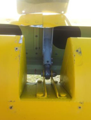
Recently a Bearhawk 4-place had a flap retraction problem on one flap because the pocket cover plate jammed into the top wing skin, and would not allow the flap to retract. The plane was still flyable, but this problem needs to be addressed.
FLAPS: On the top of the flaps the cover plate should only be deep enough to cover the gap from the flap spar to the back of the wing skin, about 1 ¼ inches, with the flap up.
AILERONS: On the aileron the cover needs to be much deeper, so that with full down aileron, the front of the cover is still under the wing skin.
15q3zbAdditional information:
Bearhawk builder Jonathan Battson experienced a case where his flap hinge pocket cover got stuck under the upper wing skin when he attempted to retract the flaps after takeoff, causing one flap to stay extended at the third notch. He writes “The jam did considerable cosmetic damage to the top skin of the wing. It was the pocket where the skins join which jammed, to the combined thickness of the two sheets of 0.025″ Aluminum, plus stiffener section.”
Jonathan also adds:
“The Bearhawk can easily be controlled with 1 flap fully deployed and the other fully retracted, even as fast as 75 KIAS. The control inputs necessary to remain straight and level (or climbing at full power), are only marginally out of balance – just enough that you would certainly notice something is wrong. You most definitely are not fighting for aileron authority, as many would have you believe, all that is required is just a little rudder and a little opposite aileron to continue in balanced flight.”