Service Notification for Patrol and LSA Kit Tail Struts

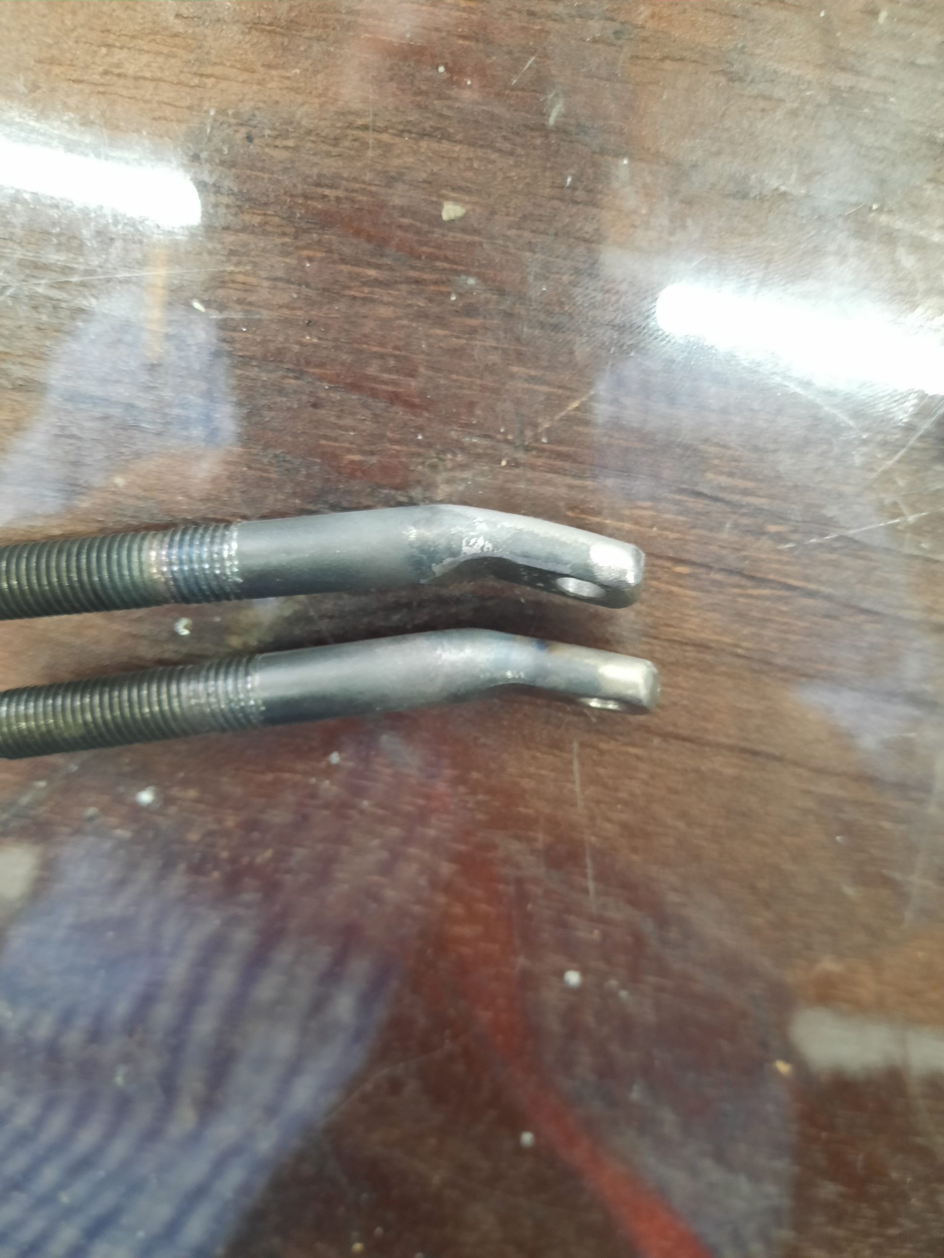
Bearhawk Aircraft Service Notification June 16, 2020 – For questions call Mark Goldberg, 512-626-7886 The horizontal stab strut for the Patrol and LSA share a common design feature on the top – how they are attached to the leading edge tube of the horizontal stab. An AN5 bolt has its head removed, and it is heated and forged flat with the 3/16” hole drilled for attaching to the horizontal stab with an AN3 bolt. The factory also cuts some more threads to add additional adjustment length. Some of these parts have left the factory improperly forged. The forged part (where the 3/16” hole is) needs to be flat so it fits flat against the bottom of the horizontal stab tube and also have the nut on the bottom fit flat. The parts not forged properly have an angle to them and are not flat on both sides. This can put stress on the AN3 bolt. There are two ways to fix this part if you have one or two that are not forged flat. One side can be ground down flat on a bench grinder if the remaining material is at least 1/8” thick. Of course any roughness or marks from the grinding would need to be polished/sanded out. Bob Barrows does a different fix for a situation like this that requires welding. A washer is tack welded to the “fatter” side of this part where the attach hole is. Then the other side of this washer is adjusted so it is flat compared to the other side. Then finish welded in place. Please inspect these parts that came with your Patrol or LSA kit. If they have this problem you should try to make the “repair” as detailed above. If you are unhappy with the result for any reason, let us know and we will replace these for you.

Plans Update for the Patrol: Forward Wing Skin Stiffener

Bob issued a plans update for the Patrol which can be found here: http://bearhawksafety.com/Patrol/february2020.html
To elaborate more, Bob says while looking at a photo of a Patrol in flight, he noticed the oil canning in the three bays on each side of the wing strut attachment point. His desire to reduce this was not a matter of structure but rather to improve the effectiveness of the airfoil, by more consistently maintaining its shape. In other words, the airfoil will perform better without the deflection. This is why there is no need to make the change to airplanes that are already past this point of construction.
In the plans photo to the right, the leading edge is at the bottom. There are two arrows pointing to the location of the new stiffener, one marked with a “*”. Making the channel as described will require a 12-foot brake. Bob says if you aren’t able to find a 12-foot brake, a 10 or 8 foot piece would be better than nothing. If you shorten the length, be sure to center the stiffener around the wing strut attach point, since that’s where the stiffness is needed.

You are not yet authorized to view this page. Learn more here.

Shock Strut Material Engineering Change for 4-Place and Patrol

The landing gear shock strut has been changed on the 4 Place Bearhawk and the Patrol. This change was done to increase gear side load capability (ground loops) and cost reduction. The streamline tubing has been replaced with round tubing (1 1/8 x .065"). The shock strut should be faired for reduced drag.
shockstruts
Scan0062
Safety update terminology: ENGINEERING CHANGE: A change to current serial number drawings onward - non-mandatory - may or may not be published. This change is the result of a product improvement, update or modification. Or a minor change of the design to ease manufacturing, maximize utility, economize materials or ease assembly.

This article is available for purchasers of 2016 Beartracks access. Click here to purchase access or validate your prior 2016 subscription. Multi-year bundles are available here.

Engineering Notice Concerning Aileron Pulley Selection

Source: 2000 Beartracks, Bob Barrows

Reference Drawing # 14 - The aileron cable pulley can be changed from a AN210-4A to the 1/2" smaller O.D. MS20220-2 if needed to allow the aileron cable to better line up with the wing strut.

If you use the MS20220-2 pulley you will need to bush its I.D. to 1/4" or use a 5/16" bolt and drill out the pulley bracket.

Inspect the line up of the aileron cable to the pulley, if not close to centered the bracket may need to be adjusted a little for proper line up.

You are not yet authorized to view this page. Learn more here.

2000 Engineering Notice Concerning Horizontal Stab/Elevator Outboard Trim Location (453 and below)

Source: 2000 Beartracks, Bob Barrows

The following Engineering Notice is Non-Mandatory. Applies to the horizontal stabilizer/elevator outboard hinge location. Drawing #20 plans serial #453 and below.

I have moved the outboard hinge to a new location 4 inches out towards the tip on drawing #20. This change is not required if you have finished fabricating your horizontal stabilizer.

Elevator spar stress levels and stiffness are improved with this running change, also the overhung ratio is more closely matched to the rudder. Upper tail wires will increase in length by 3 1/2" and lower tail wires will increase in length by 3 3/4".

Both of my Bearhawks have the original location and I do not plan to rework the tail feathers to make this change. I have had no indications of a problem to date. This change only improves the design.


You are not yet authorized to view this page. Learn more here.

1999 Engineering Notice Regarding Upper Front Door Hinge Positioning (416 and below)

Engineering Notices

Source: 1999 Beartracks, Bob Barrows

Reference plans number 416 and below, Drawing #16. As shown in the drawing below change the 5 1/2" dimension to 5 3/4" to increase clearance between door frame and bottom of the wing in the open position. If the fuselage is already welded up, adjust hinge location for needed clearance.

You are not yet authorized to view this page. Learn more here.

1998 Control Stick Engineering Notice (376 and Below)

Source: 1998 Beartracks, Bob Barrows

Refer to drawing #26 for plans serial numbers 376 and below.

The T3 control link that works inside of the 1 1/8 X .049 torque tube does not have enough clearance to use standard attach hardware as shown in view B.

Make the link as shown below so that standard hardware can be used at the cable attach locations. A 3/16" steel rivet will be need to be used at the control stick attach point. I made the rivet by cutting a AN23 clevis bolt to the 19/32" length behind the threads.

If you have already made the link you can use the AN3 bolt at the cable end with a thin nut with Loc-Tite and or peen slightly (see photo).

Another solution would be to make the .062 end brackets at an angle such that all the hardware works outside the 1 1/8 x .049 torque tube as shown above. Plans number 376 and up have this arrangement. If you would like a new drawing #26 please send $3 to cover printing & shipping cost.

The Bearhawk I am building now will use the control stick as your plans show with the 3/16" steel rivet joint at the control stick attach point. See photo above.

You are not yet authorized to view this page. Learn more here.

1998 Inboard Flap Lever Engineering Notice (280 and below)

Source: 1998 Beartracks, Bob Barrows

Reference drawings #12 and #14 for plans serial numbers 280 or below.

Inboard Flap Lever

The inboard flap lever arm was shortened from 4-1/8" to 4" for clearance with the aileron cable. If you have completed this assembly you may remove up to 1/16" from the tip of the flap lever arm for clearance.

You are not yet authorized to view this page. Learn more here.

1998 Firewall Positioning Engineering Notice (326 and below)

Refer to Drawing # 18 firewall detail.

During the assembly of the Bearhawk I am now building I found that the 7 1/2" dimension was about 1" too high. This dimension should be reduced to about 6 1/2". See corrected drawing below.

This change is needed to keep a good line from the top of the nosebowl to the top of the instrument panel and increase the tunnel area at the bottom of the firewall for better engine cooling.

Please note the size of the firewall has not been changed, it has just been positioned lower on the airframe.

Also note that depending on the type of engine you use, the shape of your nosebowl and the height you make the instrument panel may affect the vertical location of the firewall.

The minimum clearance of the engine and related components to the cowl is 1/2".

You are not yet authorized to view this page. Learn more here.